ROBBE Easy Go 3043 Assembly And Operating Instructions Manual
- Kategorie
- Ferngesteuertes Spielzeug
- Typ
- Assembly And Operating Instructions Manual
Seite wird geladen ...

Easy Go
3
Bauanleitung, Assembly instructions, Notice de montage
3043
No.
Technische Daten
Spannweite: ca. 875 mm
Gesamtflächeninhalt: ca. 20 dm
2
Fluggewicht: ca. 350 g
Nicht enthaltenes Zubehör siehe Beilageblatt
Werkzeuge und Hilfsmittel siehe robbe Hauptkatalog
Allgemeine Hinweise für den Bauablauf
Die Numerierung entspricht im wesentlichen der Reihenfolge
des Bauablaufs.
Verschaffen Sie sich in Verbindung mit den Abbildungen und
Kurztexten einen Überblick über die jeweiligen Bauschritte.
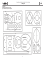
Das Auffinden der Stanzteile erleichtern die Identifikations-
zeichnungen auf Seite 22.
Verklebungen von Styropor
Klebearbeiten an Styroporteilen nur mit Weißleim oder Epoxy
ausführen.
Kleber auf Nitro- und Polyesterbasis und normaler
Sekundenkleber führen zur Zerstörung des Werkstoffs.
Zum Verkleben von Kunststoffteilen mit Styropor ausschließ-
lich Epoxy verwenden.
Epoxy-Kleber aus Gewichtsgründen sparsam und gleichmä-
ßig verteilt aufbringen.
Richtungsangaben wie z. Bsp. „rechts“ sind in Flugrich-
tung zu sehen.
Hinweise zur Fernsteueranlage
Als Fernsteuerung benötigen Sie eine Anlage ab 3 Kanälen
und 2 Servos sowie einen elektronischen Flugregler.
Orientieren Sie sich vor Baubeginn über die Einbaumöglich-
keit der zu verwendenden Fernsteuerung.
Sollte eine andere, als die von uns vorgeschlagene
Steuerung verwendet werden, können Sie sich nach dem
Einbauschema richten.
Maßdifferenzen sind von Ihnen selbst auszugleichen.
Caractéristiques techniques
Envergure 880 mm environ
Surface alaire totale 21,5 dm
2
environ
Poids en ordre de vol 350 g environ
Accessoires non contenu dans la boîte de construction,
cf. le feuillet joint
Outillage et accessoires de montage, cf. Catalogue
général robbe
Recommandations générales concernant la construction
La numérotation correspond en règle générale à l’ordre de la
construction.
Avant d’entreprendre la construction, lire attentivement les
textes explicatifs en vous reportant aux illustrations afin de
vous faire une idée d’ensemble de l’ordre des séquences
d’assemblage.
L’identification des pièces estampées est facilitée par les
schémas du page 22.
Collage du styropor
Les opérations de collage ne seront réalisées qu’avec de la
colle blanche ou de la colle époxy.
Les colles à base de nitrée ou polyester et les colles cyano-
acrylates entraînent une destruction du matériau.
Pour coller des éléments de plastique avec des pièces en
styropor, utiliser exclusivement de la colle époxy.
Pour des raisons d’économie de poids, appliquer la colle
époxy parcimonieusement mais en la distribuant de manière
homogène.
Les données directionnelles comme «droite», par exem-
ple, sont à considérer dans le sens du vol.
Recommandations concernant l’ensemble de radiocom-
mande
Il faut, pour le modèle, un ensemble de radiocommande de
quatre voies avec 2 servos et un variateur électronique.
Avant de commencer l’assemblage reporter les cotes en
fonction de l’ensemble de radiocommande utilisé.
Si vous utilisez un autre ensemble de radiocommande que
celui que nous recommandons, suivre les indications
fournies par les illustrations.
Rectifiez par vous-même les différences de cote éventuelles.
Specification
Wingspan: approx. 875 mm
Total flying surface area: approx. 20 dm
2
All-up weight: approx. 350 g
See separate sheet for details of essential items not
included in the kit.
Please refer to the main robbe catalogue for details of
tools and aids to building.
Sequence of assembly
In general terms the numbering of the kit components corre-
sponds to the sequence of assembly.
Please study the illustrations and instructions before you
start building, so that you have a clear idea from the outset
how the model goes together.
The identification drawings on page 22 are designed to help
you locate and identify the die-cut parts.
Adhesives and styrofoam
Styrofoam parts should be glued together using either white
glue or epoxy only.
Never allow cellulose-based, polyester or cyano-acrylate
adhesives to contact the styrofoam parts, as they will attack
and destroy the material.
Use epoxy for gluing all plastic parts to styrofoam.
When you have to use epoxy apply it sparingly and distrib-
ute it evenly, otherwise you can easily add excessive weight.
Directions such as „right-hand“ are as seen from the tail
of the model looking forward.
Radio control system
You will need a 4-channel radio control system with two ser-
vos and an electronic speed controller.
Before you start construction check that your RC system
components can be fitted in the position shown in the draw-
ings.
If you intend to fit an RC system other than the one we rec-
ommend, you can still follow the basic arrangement shown,
but you may have to make allowance for slight differences in
component size.

Easy Go
4
Bauanleitung, Assembly instructions, Notice de montage
3043
No.
Hinweise zu den Dekorbildern
- Die Dekorbilder können nach eigenem Ermessen aufge-
bracht werden.
- Wir empfehlen dies, bevor die Einzelteile am Modell be-
festigt werden.
- Jedes Abziehbild - Motiv einzeln ausschneiden und ca.
60 sec. in Wasser eintauchen. 60 sec. in Wasser ein-
tauchen. Tip: Die Haftung der Abziehbilder wird deutlich
erhöht, wenn auf die betreffende Stelle am Modell stark
verdünnter Weißleim aufgetragen wird. Das Motiv an
der bezeichneten Stelle vom Papier abschieben und mit
Löschpapier andrücken.
- Erst dann die obere weisse Trägerfolie entfernen.
Baukasteninhalt
Nr. Bezeichnung Stück
1 Motorspant 1
2 Aufdopplung 1
3 Rumpf 1
4 Hauptspant 1
5 Fahrwerksspant 2
6 Fahrwerk, ø 1,5 mm 1
7 Abschlußspant 1
8 Akkuschacht, Seitenteil 2
9 Akkuschacht, Rückteil 1
10 Akkuschachtboden 1
11 Servorahmen 1
12 Halbspant 1
13 Seitenleitwerk 1
14 Höhenleitwerk 1
15 Ruderhorn 2
16 Hecksporn 1
17 Tragfläche 1
18 Zusatzrahmen 2
19 Höhenrudergestänge, 488 mm 1
20 Seitenrudergestänge, 490 mm 1
21 Kunststoffrohr 1
22 Radhalbschale 4
23 Sicherungsscheibe, ø 1,7 mm 4
24 Halteklötzchen 4
Notes on the water-slide decals
- The decals can be applied in any arrangement you find
pleasing.
- We recommend that you apply them before the model’s
components are assembled.
- Cut out each individual decal and place it in water for
about 60 seconds. Tip: the decals adhere much more
strongly if a coat of highly thinned white glue is applied
to that area of the model beforehand and allowed to dry.
Slide the decal off the paper and into position, and press
down gently using blotting paper.
- Do not remove the top backing film until this stage.
Kit contents
No. Description No. off
1 Motor bulkhead 1
2 Doubler 1
3 Fuselage 1
4 Main former 1
5 Undercarriage former 2
6 Undercarriage, 1.5 mm Ø 1
7 In-fill former 1
8 Battery box side panel 2
9 Battery box rear panel 1
10 Battery box bottom 1
11 Servo frame 1
12 Half-former 1
13 Fin 1
14 Tailplane 1
15 Horn 2
16 Tailskid 1
17 Wing 1
18 Supplementary servo frame 2
19 Elevator pushrod, 488 mm 1
20 Rudder pushrod, 490 mm 1
21 Plastic guide tube 1
22 Wheel shell 4
23 Starlock washer, 1.7 mm Ø 4
24 Retaining block 4
Recommandations concernant l’application des transferts.
- Disposer les transferts selon vos goûts sur le modèle.
- Nous vous conseillons de les appliquer sur les éléments du
modèle avant de mettre ceux-ci en place.
- Découper chacun des transferts et les tremper approxima-
tivement 60 secondes dans l’eau. Un conseil : l’adhérence
des transferts est nettement améliorée lorsque les emplace-
ments du modèle sur lesquels ils sont appliqués sont préal-
ablement enduits de colle cellulosique diluée.. Appliquer le
motif du transfert à l’emplacement choisi et le décoller du
papier avant de le tamponner avec un buvard.
- Retirer ensuite seulement le film blanc de surface.
Contenu de la boîte de construction
N° désignation nbre
1 couple moteur 1
2 renfort 1
3 fuselage 1
4 couple principal 1
5 couple d’atterrisseur 2
6 atterrisseur 1
7 couple de fermeture 1
8 compartiment de l’accu, paroi latérale 2
9 compartiment de l’accu, paroi arrière 1
10 fond du compartiment de l’accu 1
11 châssis du servo 1
12 demi-couple 1
13 dérive 1
14 stabilisateur 1
15 guignol 2
16 éperon arrière 1
17 aile 1
18 châssis supplémentaire 2
19 tringle de gouverne de prof.,488 mm 1
20 tringle de gouverne direction, 490 mm 1
21 tube en plastique 1
22 demi-coquille de roue 4
23 rondelle d’arrêt 4
24 cales 4

Easy Go
5
Bauanleitung, Assembly instructions, Notice de montage
3043
No.
25 Spinnerscheibe 1
26 Spinnerscheibe 1
27 Spinner 1
28 Blechschraube, ø 2,2 x 9 mm 4
29 Getriebe 4,5 : 1 1
30 Blechschraube, ø 2,2 x 9 mm 2
31 Zwischenlage, 4 x 12 x 23,5 mm 1
32 Luftschraubenmutter, M 8 1
33 Cockpitscheibe 1
34 Abziehblider 1
25 Rear spinner backplate 1
26 Front spinner backplate 1
27 Spinner cone 1
28 Self-tapping screw, 2.2 Ø x 9 mm 4
29 Gearbox, 4.5:1 1
30 Self-tapping screw, 2.2 Ø x 9 mm 2
31 Spacer washer, 4 x 12 x 23.5 mm 1
32 Propeller nut, M8 1
33 Windscreen 1
34 Water-slide decals
25 rondelle de cône d’hélice 1
26 rondelle de cône d’hélice 1
27 cône d’hélice 1
28 vis autotaraudeuse, Ø 2,2 x 9 4
29 mécanisme 4,5:1 1
30 vis autotaraudeuse, Ø 2,2 x 9 mm 2
31 intercalaire, 4 x 12 x 23,5 mm 1
32 écrou d’hélice, M 8 1
33 vitre du cockpit 1
34 transferts 1
Seite wird geladen ...

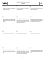
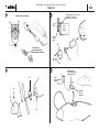
Fig.1
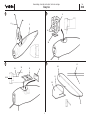
- Coller ensemble de couple moteur 1 et le renfort 2.
Fig. 2
- Coller le couple dans le fuselage 3. Vu du dessus, il faut
que le moteur présente ultérieurement un piqueur et un
anticouple de 3° chacun.
Fig. 3
- Au couple principal 4, coller de chaque côté les couples
d’atterrisseur 5 parfaitement superposés.
Fig. 4
- Coller l’atterrisseur principal 6 et le couple de fermeture 7
dans le couple principal 4.
Easy Go
7
Bauanleitung, Assembly instructions, Notice de montage
3043
No.
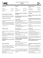
Fig. 1
- Glue the motor bulkhead to the doubler.
Fig. 2
- Glue the motor bulkhead inside the fuselage 3. The motor
must have about 3° of downthrust, and about 3° right
sidethrust when viewed from above.
Fig. 3
- Glue the undercarriage formers 5 to both sides of the
half-former 4.
Fig. 4
- Glue the main undercarriage 6 and the in-fill former 7 to
the main former 4.
Bild 1
- Motorspant und Aufdoppelung miteinander verkleben.
Bild 2
- Den Motorspant in den Rumpf 3 kleben. Von oben gese-
hen muß der Motor später einen Sturz und einen
Seitenzug nach rechts von jeweils ca. 3° aufweisen -
Sichtprüfung.
Bild 3
- Am Hauptspant 4 beidseitig die Fahrwerksspanten 5
deckungsgleich verkleben.
Bild 4
- Hauptfahrwerk 6 und Abschlußspant 7 in den Hauptspant
4 kleben.
Seite wird geladen ...

Easy Go
9
Bauanleitung, Assembly instructions, Notice de montage
3043
No.
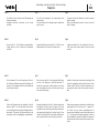
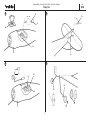
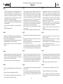
Bild 5
- Die Schlitze für das Fahrwerk 6nach Markierungen im
Rumpf einschneiden.
- Hauptspant einsetzen, ausrichten und im Rumpf
verkleben.
Bild 6
- Aus den Teilen 8 - 10 die Akkubox zusammenkleben.
Fertige Akkubox in den Schlitzen des Hauptspants
verkleben.
Bild 7
- Den Servorahmen 11 so in den Rumpf setzen, daß er in
die Schlitze der Batteriebox eingreift. Den Halbspant 12
einsetzen. Teile zueinander ausrichten und miteinander
und im Rumpf verkleben.
Bild 8
- Seiten- und Höhenruder von den Leitwerken 13 und 14
abtrennen. Spalt "S" (ca. 30°) anschleifen. Über die Kan-
ten ohne Spalt jeweils einen Streifen Klebeband als Ru-
derscharnier "R" spannen. Die Ruder mehrfach hin- und
herbewegen, um die Leichtgängigkeit zu gewährleisten.
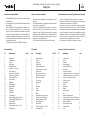
Fig. 5
- Cut slots in the fuselage for the undercarriage at the
marked points.
- Fit the main former in the fuselage, align it carefully and
glue it in place.
Fig. 6
- Assemble the battery box from parts 8 - 10. Glue the com-
pleted battery box in the slots in the main former.
Fig. 7
- Place the servo frame 11 in the fuselage and fit its lugs in
the slots in the battery box. Install the half-former 12.
Position the components carefully relative to each other
and check alignment once more. Glue the parts to each
other and to the fuselage.
Fig. 8
- Separate the rudder from the fin 13, and the elevator from
the tailplane 14. Sand the bevel „S“ (approx. 30°) at the
hinge pivot line as shown. Apply a full-length strip of adhe-
sive tape along the hinge lines to form the hinge „R“; there
should be no visible gap. Move the rudder and elevator to
and fro several times to ensure that they move freely.
Fig. 5
- Découper les fentes de l’atterrisseur 6 selon les repères
dans le fuselage.
- Mettre le couple principal en place, le centrer et le coller
dans le fuselage.
Fig. 6
- À partir des éléments 8 à 10, assembler le bac d’accu.
Coller le bac d’accu terminé dans les fentes du couple
principal
Fig. 7
- Installer le châssis porte-servos dans le fuselage de telle
sorte qu’il s’engage dans les fentes du bac d’accu. Mettre
le demi-couple 12 en place. Centrer les éléments les uns
par rapport aux autres et les coller ensemble et au fuse-
lage.
Fig. 8
- Détacher les gouvernes de profondeur et de direction des
empennages 13 et 14. Poncer le jour « S » (approx. 30°).
Sur l’arête sans jour tendre systématiquement un
morceau de ruban adhésif comme charnière de gouverne
« R ». Sur la gouverne de direction appliquer un morceau
de ruban adhésif de chaque côté. Déplacer les gouvernes
plusieurs fois dans les deux sens afin d’en assurer la sou-
plesse.
Seite wird geladen ...

Easy Go
11
Bauanleitung, Assembly instructions, Notice de montage
3043
No.
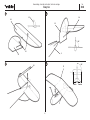
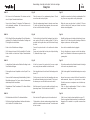
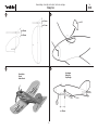
Bild 9
- Ruderhörner 15 mit 1 mm bohren und in eingeschnittene
Schlitze der Ruder einkleben.
Bild 10
- Höhen- und Seitenleitwerk 13 und 14 rechtwinklig zusam-
menkleben. Einheit in den Rumpf kleben. Auf korrekten
Sitz achten.
Bild 11
- Den Hecksporn 16 unten an das Seitenleitwerk kleben.
Bild 12
- Die Tragfläche mittig auf den Rumpf kleben. X rechts = X
links. Die Fläche muß rechtwinklig zur Rumpflängsachse
sitzen.
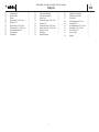
Fig. 9
- Drill a 1 mm Ø hole in each horn 15, and glue them in
slots in the control surfaces.
Fig. 10
- Glue the tailplane 13 and fin 14 together at right-angles.
Install this assembly in the fuselage and glue the parts
together. Check carefully that everything is „square“
before leaving the glue to set hard.
Fig. 11
- Glue the tailskid 16 to the bottom edge of the fin.
Fig. 12
- Glue the wing to the wing saddle on the underside of the
fuselage, taking care to set it exactly central. The dimen-
sions X left and X right must be identical. The wing must
also be at right-angles to the fuselage centreline.
Fig. 9
- Percer un trou de 1 mm dans les guignols 15 et les coller
dans les fentes des gouvernes.
Fig. 10
- Assembler les gouvernes de profondeur et d direction 13
et 14 à angle droit et les coller. Coller l’unité dans le fuse-
lage. Veiller à ce que son assise soit correcte.
Fig. 11
- Coller l’éperon de queue 16 sous la dérive.
Fig. 12
- Coller l’aile au centre sur le fuselage, X droite = X gauche.
L’aile doit être perpendiculaire à l’axe longitudinal du fuse-
lage.
Seite wird geladen ...

Easy Go
13
Bauanleitung, Assembly instructions, Notice de montage
3043
No.
Bild 13
- Die Servos in die Zusatzrahmen 18 einsetzen und mit
einem Tropfen Sekundenkleber fixieren.
- Servos in den Rahmen 11 einsetzen. Die Rahmen noch
nicht miteinander verkleben. Die Servos müssen noch
verschiebbar bleiben.
Bild 14
- Die Schlitze für Höhenrudergestänge 19 und Seitenruder-
gestänge 20 im Rumpfheck einschneiden. Gestänge mit
Führungsröhrchen einschieben.
- Enden in den Ruderhörnern einhängen.
- Zur Sicherung ein kurzes Stück Kunststoffrohr 21 auf das
Ende schieben und mit einem Tropfen Sekundenkleber
sichern.
Bild 15
- In der gleichen Art das vordere Ende der Gestänge in den
Servohebeln einhängen.
- Führungsröhrchen am Rumpfende und an Spant 12 ver-
kleben.
- Servos mit der Fernsteuerung in Neutralstellung, Ruder in
Mittelstellung bringen. Die Servos mit den Zusatzrahmen
dabei entsprechend verschieben.
- Zusatzrahmen 18 am Servorahmen 11 in dieser Position
verkleben.
Bild 16
- Die Halbschalen der Räder 22 aufeinanderkleben.
- Die Räder auf dem Hauptfahrwerk mit den selbstsichern-
den Scheiben 23 frei drehbar sichern.
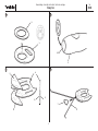
Fig. 13
- Place the servos in the supplementary frames 18 and
secure them with a drop of cyano.
- Place the supplementary frames in the main servo frame
11, but do not glue the frames together; the servos must
be free to slide to and fro at this stage.
Fig. 14
- Cut the slots in the tail end of the fuselage to clear the ele-
vator pushrod 19 and the rudder pushrod 20. Slip the
pushrods into the guide tubes, and fit the tubes through
the slots.
- Connect the pushrod ends to the rudder and elevator
horns.
- Secure each pushrod with a short piece of plastic tubing
21, fixed with a drop of cyano.
Fig. 15
- At the front connect the pushrods to the servo output
arms, using the same method to retain the ends.
- Glue the guide tubes to the tail end of the fuselage and to
former 12.
- Set the servos to centre from the transmitter, and move
the rudder and elevators to centre (neutral). This is possi-
ble because you can still slide the servos to and fro.
- Hold the servos in the correct position, and glue the sup-
plementary frames 18 to the main servo frame 11.
Fig. 16
- Glue the shells 22 together in pairs to form the wheels.
- Fit the wheels on the main undercarriage and retain them
with the four starlock washers as shown. The wheels must
be free to rotate.
Fig. 13
- Installer les servos dans le châssis supplémentaire 18 et
les y fixer avec une goutte de colle cyanoacrylate.
- Mettre les servos en place dans le châssis 11. Ne pas
coller les châssis l’un à l’autre pour l’instant. Les servos
doivent rester déplaçables.
Fig. 14
- Entailler les fentes pour les tringles de direction et de pro-
fondeur 20 et 19 dans la queue du fuselage. Mettre les
tringles en place avec des tubes-guides.
- Accrocher les extrémités dans les guignols.
- Pour les fixer glisser un morceau court de tube de plas-
tique 21 sur l’extrémité et le fixer avec une goutte de colle
cyanoacrylate.
Fig. 15
- De la même manière traiter l’extrémité avant de la tringle
et l’accrocher au palonnier du servo.
- Coller le tube-guide à l’extrémité du fuselage et au couple
12.
- Amener les servos au neutre à l’aide de l’ensemble de
radiocommande, disposer les gouvernes au neutre.
Décaler les servos en conséquence avec le châssis sup-
plémentaire.
- Coller le châssis supplémentaire 18 dans le châssis
porte-servos 11 dans cette position.
Fig. 16
- Coller l’une sur l’autre les demi-coquilles des roues 22.
- Fixer les roues dans l’atterrisseur avec les rondelles auto-
bloquantes 23 de manière à ce qu’elles conservent leur
mobilité.
Seite wird geladen ...

Easy Go
15
Bauanleitung, Assembly instructions, Notice de montage
3043
No.
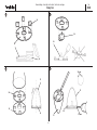
Bild 17
- Die Klötzchen 24 aus einer Leiste herstellen und
nacheinander in die Aussparungen der Spinnerscheibe
25 kleben. Klötzchen anschrägen.
Bild 18
- Die Scheibe 25 auf das Innenzahnrad des Getriebes29
setzen. Achtung: Die Scheibe darf das Innenzahnrad
nicht verformen, da das Getriebe sonst später unrund
läuft. Falls erforderlich die innere Bohrung vorsichtig zen-
trisch nachschleifen.
- Innenzahnrad vom Getriebegehäuse lösen und in die
Scheibe einsetzen. Zahnrad und Scheibe müssen fluch-
ten. Die Verklebung auf einer, mit Folie abgedeckten, ebe-
nen Unterlage vornehmen.
Bild 19
- Scheibe 26 auflegen und rundum so verschleifen, daß der
Spinner 27 aufgesetzt werden kann. Der Spinner muß
zentrisch sitzen.
- Einheit 26 / 27 vorsichtig abnehmen und die Teile
miteinander verkleben. Nicht mit 25 verkleben.
Bild 20
- Spinner aufsetzen und Löcher für die Befestigung des
Spinners mit ø 1,5 mm in die Klötzchen 24 bohren.
- Scheibe 26 und den Spinner so ausschneiden, daß er
über die vorgesehene Luftschraube paßt.
Fig. 17
- Cut the blocks 24 from a length of strip, and glue them in
the notches in the rear spinner backplate 25. Bevel the
outside face of the blocks as shown.
Fig. 18
- Place the rear spinner backplate 25 over the internal gear
of the gearbox 29. Caution: check that the backplate does
not push the internal gear out of shape, otherwise the
gearbox will not run true when assembled. If necessary,
sand the inner hole in the backplate until the assembly is
exactly central.
- Remove the internal gear from the gearbox housing, fit it
in the rear spinner backplate, and check that the gear and
backplate line up correctly. Lay plastic film over a flat sur-
face, and glue the parts together resting flat on the sur-
face.
Fig. 19
- Place the front spinner backplate 26 over this assembly,
and sand it back lightly all round until it is a snug fit inside
the spinner cone 27. The spinner must be exactly central,
otherwise it will wobble.
- Carefully separate the assembly 26 / 27, and glue these
two parts together. Don’t glue these parts to part 25.
Fig. 20
- Place the spinner cone assembly on the rear backplate
and mark the position of the spinner retaining holes on the
blocks 24. Drill the holes 1.5 mm Ø.
- Cut away the spinner backplate 26 and the spinner cone
to accept the propeller you intend to use.
Fig. 17
- Réaliser les cales 24 à l’aide d’une baguette et les coller
l’une après l’autre dans les dégagements de la rondelle
de cône d’hélice 25. Biaiser les cales.
Fig. 18
- Installer la rondelle 25 sur la roue dentée intérieure du
mécanisme 29. Attention : la rondelle ne doit en aucun
cas déformer la roue dentée intérieure faute de quoi le
mécanisme présenterait un balourd par la suite. Si néces-
saire, limer de manière centrée l’alésage intérieur en
procédant avec précaution.
Fig. 19
- Mettre la rondelle 26 en place et en poncer la circon-
férence de telle sorte qu’il soit possible de mettre le cône
d’hélice en place. Le cône doit être parfaitement centré.
- Retirer l’unité 26/27 avec précaution et coller les éléments
l’un après l’autre. Ne pas coller la pièce 25.
Fig. 20
- Mettre le cône en place et percer les trous de fixation du
cône avec une mèche de Ø 1,5 mm dans les cales 24.
- Entailler la rondelle 26 et le cône de telle sorte qu’il
s’adapte à l’hélice prévue.

Easy Go
16
Bauanleitung, Assembly instructions, Notice de montage
3043
No.
21 22
23 24
31
28
32
29
30
Stecksystem
connector system
Système de connexion
Schema, scheme, schéma
F
28
30
25
27
Ritzel
Pinion
Pignon
Motor
Motor
Moteur
Unterlegscheibe 4 x 12 x 23,5 mm
Washer 4 x 12 x 23.5 mm
Rondelle 4 x 12 x 23,5 mm
Doppelklebeband
Double sided foam tape
Adhésif double face
Regler
Speed controller
Variateur
Empfänger
Receiver
Récepteur

Easy Go
17
Bauanleitung, Assembly instructions, Notice de montage
3043
No.
Bild 21
- Den Motor entstören. Dazu die Kondensatoren 100 nF
jeweils mit einem Beinchen an das Gehäuse löten, wel-
ches dazu blankzufeilen ist. Zweites Beinchen mit
Isolierschlauch an die Motorpole stecken. Die Beinchen
des Kondensators 47 nF mit Isolierschlauch versehen
und ebenfalls an die Motorpole stecken.
- Ferritkern "F" aufdas Motoranschlußkabel schieben.
Kabel an die Motorpole löten, die Kondensatoren werden
dabei mitverlötet.
- Das Stecksystem anbringen. Auf richtige Polarität ach-
ten.
- Regleranleitung beachten.
Bild 22
- Motorwelle mit Schleifpapier in Längsrichtung aufrauhen.
- Etwas Loctite in die Bohrung des Ritzels träufeln. Das
Ritzel auf die Motorwelle aufpressen.
- Die Unterlegscheibe 31 als Zwischenlage einlegen und das
Getriebegehäuse 29 auf den Motor stecken.
- Antrieb einschieben, ø 1,5 mm Löcher bohren. Antrieb be-
festigen.
Bild 23
- Innenzahnrad gut fetten. Spinnerscheibe mit Getriebe auf
die Welle stecken und mit Sicherungsring festsetzen. Luft-
schraube auf 8 mm zentrisch aufbohren, auf die Welle
schieben und mit der M 8 Mutter sichern.
- Spinner aufsetzen und mit 4 Schrauben 28 befestigen.
Bild 24
- Den Regler mit Doppelklebeband an der Akkubox befesti-
gen.
- Regler und Servos am Empfänger anschließen.
- Den Empfänger mit Doppelklebeband im Rumpf befesti-
gen. Litzenantenne nach außen verlegen.
Fig. 21
- Suppress the electric motor as follows: file an area of the
motor can bright and clean, and solder one pin of each of
the 100 nF capacitors to the motor case. Fit an insulating
sleeve on the second pin of each capacitor and push
these pins through the two motor terminals. Fit insulating
sleeves on both pins of the 47 nF capacitor and push
them through the motor terminals to form a bridge.
- Slip the ferrite ring „F“ over the motor power cable. Solder
the two wires in the cable to the motor terminals, solder-
ing the capacitors in place at the same time.
- Attach the connectors to the wires, taking care to maintain
correct polarity.
- Read the instructions supplied with the speed controller.
Fig. 22
- Roughen the motor shaft with abrasive paper horizontal-
ly.
- Apply a drop of Loctite to the hole in the pinion. Press the
pinion onto the motor shaft.
- Place the spacer washer 31 on the shaft, and fit the gear-
box housing 29 on the motor.
- Fit the geared motor assembly into the nose bulkhead
and mark the position of the fixing screw holes. Drill the
holes 1.5 mm Ø and fit the screws 30 to retain the motor.
Fig. 23
- Grease the internal gear generously. Slide the spinner
backplate / gear assembly onto the shaft, and secure it
with the circlip. Open up the centre bore in the propeller
to 8 mm Ø, taking care to keep the hole exactly central.
Fit the propeller on the shaft and secure it with the M8 nut.
- Fit the spinner and secure it with the four screws 28.
Fig. 24
- Fix the speed controller to the battery box using double-
sided foam tape.
- Connect the speed controller and servos to the receiver.
- Fix the receiver to the fuselage using double-sided foam
tape. Run the aerial out of the fuselage and secure the
end.
Fig. 21
- Antiparasiter le moteur. Pour ce faire, souder les conden-
sateurs 100 nF chaque fois sur une des broches et au
carter du moteur qui aura été au préalable limé. L’autre
broche sera plantée avec un morceau de gaine isolante
sur les pôles du moteur. Munir les roches du condensa-
teur 47 nF de morceaux de gaine isolante et les planter
également sur les pôles du moteur.
- Glisser le noyau de ferrite « F » sur le cordon de connex-
ion du moteur. Souder le cordon aux pôles du moteur en
soudant simultanément les condensateurs.
- Mettre le système de connexion en place. Veiller à la
polarité.
- Tenir compte des indications de la notice du variateur.
Fig. 22
- Poncer l’arbre du moteur avec du papier de verre en
direction horizontal.
- Disposer une goutte de Loctite dans le trou du pignon.
Planter le pignon sur l’arbre du moteur.
- Installer la rondelle 31 comme intercalaire et planter le
carter du mécanisme 29 sur le moteur.
- Engager l’entraînement, percer les trous de Ø 1,5 mm.
Fixer l’entraînement.
Fig. 23
- Bien graisser la roue dentée intérieure. Planter la rondelle
du cône d’hélice avec le mécanisme sur l’arbre et l’y fixer
avec la bague d’arrêt. Percer un trou de Ø 8 mm au cen-
tre de l’hélice, la glisser sur l’arbre et l’y fixer avec l’écrou
M 8.
- Mettre le cône en place et le fixer avec 4 vis 28.
Fig. 24
- Fixer la variateur avec du double face au bac d’accu.
- Raccorder le variateur et les servos au récepteur.
- Fixer le récepteur avec des morceaux de double face
dans le fuselage. Disposer l’antenne souple du récepteur
vers l’extérieur.

Easy Go
18
Bauanleitung, Assembly instructions, Notice de montage
3043
No.
25 26
27 28
ca. 15 mm
ca. 15 mm
ca. 40 mm
ca. 40 mm
33
Auswiegen
Balancing
Equilibrage
Decorbilder
Decals
Autocollants
ca. 65 mm
C.G.

Easy Go
19
Bauanleitung, Assembly instructions, Notice de montage
3043
No.
Bilder 25 und 26
- Empfangsanlage betriebsbereit zusammenstecken.
- Laufrichtung der Ruder und Ruderausschläge prüfen.
- Motorlauf prüfen.
- Der Motor muß von vorn gesehen gegen den Uhrzei-
gersinn drehen. Ist dies nicht der Fall, die Kabel an den
Motorpolen durch Umlöten vertauschen.
- Achtung: Bei allen Montage-, Wartungs- und Einstellar-
beiten niemals in den Drehkreis der Luftschraube ger-
aten - Verletzungsgefahr.
- Windschutzscheibe 33 aufkleben.
Bild 27
- Dekorbilder aufbringen.
Bild 28
Auswiegen
- Den Schwerpunkt „C.G.“ beidseitig am Rumpf anzeichnen.
- Das Modell komplett zusammenbauen.
- Den Akku einlegen und mit Schaumgummi gegen Verrut-
schen sichern.
- Das Modell im Schwerpunkt unterstützen und auspendeln
lassen. Die Idealstellung ist erreicht, wenn das Modell mit
leicht nach unten hängendem Vorderteil in der Waage
bleibt.
- Hängt das Leitwerk nach unten, muß vorn Trimmblei zuge-
geben werden. Wenn das Rumpfvorderteil zu stark nach
unten hängt, hinten mit Trimmblei korrigieren.
- Trimmblei, welches in das Styropor eingedrückt wird, mit
Epoxy sichern.
Fig. 25 and 26
- Connect the receiving system components, ready to use.
- Check that the rudder and elevator move in the correct
directions, and that the control travels are correct.
- Check that the motor control system works properly.
- When viewed from the front the propeller must rotate
anti-clockwise. If this is not the case, swap over the
wires at the motor terminals to reverse the motor.
- Caution: whenever you are working on the model for
maintenance or adjustment with the battery connect-
ed, keep your fingers well clear of the rotational plane
of the propeller - injury hazard!
- Glue the windscreen 33 to the fuselage.
Fig. 27
- Apply the waterslide decals to the model.
Fig. 28
Balancing
- Mark the Centre of Gravity „CG“ on both sides of the fuse-
lage.
- Assemble the model completely, ready to fly.
- Place the flight battery in the model and pack it with foam
rubber to prevent it shifting.
- Support the model at the marked points and allow it to
hang freely. Ideally the model will balance level, with the
nose inclined slightly down.
- If the tail hangs down, add lead ballast at the nose. If the
nose hangs down too far, correct with a little lead ballast
at the tail.
- Any lead ballast can simply be pushed into the styrofoam
and secured with a dab of epoxy.
Fig. 25 et 26
- Raccorder l’ensemble de réception de manière à ce qu’il
soit en ordre de marche.
- Vérifier le sens du débattement des gouvernes et leur
importance.
- Vérifier le sens de rotation du moteur.
- Vu de l’avant, le moteur doit tourner dans le sens con-
traire des aiguilles d’une montre. Si ce n’est pas le
cas, inverser les brins au niveau des pôles du moteur
en les dessoudant avant de les ressouder.
- Attention : pour toutes les opérations de montage, de
maintenance et de réglage, ne jamais s’approcher du
plan de rotation de l’hélice – risque de blessure.
- Coller le pare-brise 33.
Fig. 27
- Appliquer les autocollants de décoration.
Fig. 28
Équilibrage
- Marquer le centre de gravité « C.G. » de chaque côté.
- Assembler complètement le modèle.
- Mettre l’accu en place et l’envelopper dans de la mousse
plastique de sorte qu’il ne puisse glisser.
- Caler le modèle au niveau du centre de gravité et le laiss-
er en suspens. Il atteint sa position idéale lorsqu’il
demeure en équilibre avec le nez légèrement piqueur.
- Si les empennages pendent vers l’arrière, il faut ajouter
du plomb de lestage à l’avant. Si le nez de l’appareil pend
trop vers l’avant, ajouter du plomb de lestage à l’arrière
pour corriger.
- Fixer le plomb de lestage avec de la colle époxy dans le
styropor.

Easy Go
20
Bauanleitung, Assembly instructions, Notice de montage
3043
No.
Einfliegen, Flughinweise
- Für den Erstflug einen möglichst windstillen Tag aus-
suchen. Als Gelände eignet sich eine flache, freie Wiese.
Nähe von Hochspannungsleitungen, verkehrsreichen
Straßen, Ansiedlungen und Flugplätzen sowie anderen
Hindernissen meiden.
- Nochmals eine Funktionskontrolle durchführen.
- Immer den Gasknüppel in Stellung „Motor aus“ bringen,
den Sender einschalten. Erst dann den Akku anschlie-
ßen.
- Zum Ausschalten immer die Verbindung Akku - Motorreg-
ler trennen, erst dann Empfangsanlage und den Sender
ausschalten.
- Für den Handstart sollte ein Helfer anwesend sein, der
das Modell in die Luft befördern kann.
- Das Modell mit laufendem Motor mit nicht zu geringem
Schub gerade und horizontal aus der Hand starten. Sofort
die Steuerung übernehmen.
- Nach dem Start den Steigflug nicht zu früh einleiten, son-
dern das Modell in flachem Horizontalflug Fahrt aufneh-
men lassen.
- Überzogene Flugzustände vermeiden. In diesem Fall
nachdrücken und in den Horizontalflug übergehen.
- Falls erforderlich, die entsprechenden Ruder nachtrim-
men.
- Das Flugverhalten genau beobachten. Sind Korrekturen
erforderlich, so sind diese nach der ersten Landung vor-
zunehmen.
- Das Modell kann auch vom Boden gestartet werden. Es
eignet sich eine Hartbelagpiste.
- Vor dem ersten Bodenstart einige Rollversuche durchfüh-
ren, um sich mit dem Verhalten des Modells am Boden
vertraut zu machen.
Test flying, flying notes
- Wait for a day with as little breeze as possible for the
model’s first flight, and seek out a large, flat, unobstructed
meadow for a flying site. Keep well clear of high-tension
overhead cables, busy roads, residential areas and air-
fields, and all obstacles.
- Repeat the check of all the working systems.
- Move the throttle stick to the „motor stopped“ position
before you switch the transmitter on, and only then con-
nect the battery. This is the standard sequence which you
should always observe.
- To switch off the system always disconnect the battery
from the speed controller first, and only then switch off the
receiving system and the transmitter.
- For a hand-launch you will need the assistance of a friend
who is experienced in hand-launching small models.
- Start the motor and give the model a reasonably strong
launch with the wings and fuselage level. Take control of
the model the moment it leaves the launcher’s hand.
- Allow the model to fly straight and level for a few seconds
to pick up speed before gently easing it into a climb. Don’t
climb too soon.
- Avoid stalling the model at this stage. If it slows down too
much, apply slight down-elevator and resume level flight
to pick up more speed.
- Adjust the transmitter trims if necessary.
- Watch the model’s behaviour in the air very carefully. If
you need to make corrections or adjustments, carry them
out immediately the model is back on the ground.
- The model can also be taken off from the ground; you will
need a smooth, hard surface for a successful take-off.
- Carry out a few taxi-ing runs initially to get used to the
model’s handling on the ground.
Le premier vol, conseils de pilotage
- Pour le premier vol, choisir autant que possible un jour
sans vent. Le terrain pourra être constitué d’une prairie
dégagée, sans relief. Éviter le voisinage de lignes à haute
tension, de routes encombrées, de lotissements et
d’aéroports et d’autres obstacles.
- Vérifier à nouveau toutes les fonctions.
- Amener systématiquement les manche des gaz en posi-
tion « moteur arrêté » avant de mettre l’émetteur en
marche. Ne raccorder l’accu qu’ensuite.
- Après une séance de vol, désolidariser toujours d’abord
l’accu du variateur avant de couper l’ensemble de récep-
tion puis le récepteur.
- Pour le lancement manuel, demander l’assistance d’un
tiers qui lancera le modèle.
- Lancer le modèle moteur en marche sur une trajectoire
rectiligne avec une poussée conséquente. Prendre immé-
diatement les commandes.
- Après le lancement, n’entamer pas immédiatement de vol
ascensionnel mais laisser plutôt le modèle prendre de la
vitesse en un long vol rectiligne.
- Éviter tout cabrage. Dans ce cas, pousser sur le manche
de profondeur afin de reprendre une assiette normale.
- Si nécessaire, corriger au niveau du trim de la gouverne
appropriée.
- Observer précisément le comportement en vol de l’ap-
pareil. Si des corrections s’imposent, les appliquer immé-
diatement après l’atterrissage.
- Il est également possible de faire décoller le modèle du
sol. Il faut, dans ce cas, disposer d’une piste en dur.
- Avant d’effectuer le premier décollage du sol, réaliser des
essais de roulage afin de vous familiariser avec le com-
portement de l’appareil au sol.

Easy Go
21
Bauanleitung, Assembly instructions, Notice de montage
3043
No.
- Sind Ihnen die Reaktionen des Modells bekannt, wird das
Modell mit der Nase genau gegen den Wind gestellt.
- Kontinuierlich bis zur vollen Motorleistung Gas geben und
das Modell durch leichtes Ziehen des Höhenruders vom
Boden abheben. Das Modell nicht überziehen. Falls erfor-
derlich, sofort nachtrimmen.
Reparaturen
- Bei einer eventeuell erforderlichen Reparatur an Styropor-
teilen wie folgt vorgehen:
- Bruchstelle freilegen. Die Bruchstelle so wenig wie möglich
verändern.
- Die Teile unter Zugabe von Epoxy wieder paßgenau zu-
sammenfügen und ausrichten.
- Die Klebestelle gut aushärten lassen.
- Bei fehlenden Bruchstücken diese durch gleichwertiges
Styropormaterial ersetzen.
robbe Modellsport GmbH & Co. KG
Technische Änderungen vorbehalten
- Once you feel confident about the model’s control
response, place it on the ground with the nose pointing
exactly into wind.
- Steadily advance the stick until the motor is at full throttle,
allow the model to gain plenty of speed on the ground,
then apply slight up-elevator to lift off. Adjust the trims
immediately if necessary.
Repairs
- If you should ever need to repair the styrofoam parts, this
is the procedure:
- Expose the break completely. Otherwise do not modify
the broken surfaces at all.
- Apply a thin coating of epoxy to the break, push the parts
back together and align them carefully.
- Allow the glue to harden fully.
- If you lose any part of the broken component, cut a new
piece from styrofoam of the same grade.
robbe Modellsport GmbH & Co. KG
We reserve the right to alter technical specifications.
- Lorsque vous avez assimilé les réactions de l’appareil,
l’installer exactement face au vent.
- Donner des gaz jusqu’à ce que le régime plein gaz soit
atteint et laisser rouler le modèle avant de tirer légère-
ment sur le manche de profondeur afin qu’il décolle du
sol. Ne pas trop tirer sur le manche. Si nécessaire, cor-
riger immédiatement au niveau des trims.
Réparations
- Si des réparations s’imposent sur les éléments en styro-
por, procéder comme suit :
- dégager la cassure. La modifier le moins possible.
- Assembler les deux parties avec exactitude après les
avoir enduites de colle époxy et les aligner.
- Bien laisser durcir la colle.
- Remplacer les morceaux de styropor manquant au niveau
de la cassure par du matériel équivalent.
robbe Modellsport GmbH & Co. KG
Sous réserve de modification technique.
Seite wird geladen ...

robbe Modellsport GmbH & Co. KG
Metzloserstr. 36
Telefon: 06644 / 87-0
36355 Grebenhain
IAA
-
 1
1
-
 2
2
-
 3
3
-
 4
4
-
 5
5
-
 6
6
-
 7
7
-
 8
8
-
 9
9
-
 10
10
-
 11
11
-
 12
12
-
 13
13
-
 14
14
-
 15
15
-
 16
16
-
 17
17
-
 18
18
-
 19
19
-
 20
20
-
 21
21
-
 22
22


ROBBE Easy Go 3043 Assembly And Operating Instructions Manual
- Kategorie
- Ferngesteuertes Spielzeug
- Typ
- Assembly And Operating Instructions Manual
in anderen Sprachen
- English: ROBBE Easy Go 3043
- français: ROBBE Easy Go 3043
Verwandte Artikel
-
ROBBE Bucker Jungmeister 3041 Assembly And Operating Instructions Manual
-
-
-
-
-
-
-
ROBBE Arcus Assembly And Operating Instructions Manual
-
-