
AUTOMIG 223i/273i
AUTOMIG 223i/273i Boost
AUTOMIG 223i DUO
AUTOMIG 223i DUO Boost
Brugsanvisning
Instruction manual
Betriebsanleitung
Manuel d'instruction
Bruksanvisning
Käyttöohje
Gebruikershandleiding
Manuale d'istruzione
Kezelési útmutató
Instrukcja obsługi
Valid from 2012 week 04 50111822 G

EC DECLARATION OF CONFORMITY
MIGATRONIC A/S
Aggersundvej 33
9690 Fjerritslev
Denmark
hereby declare that our machine as stated below
Type: AUTOMIG 273i
As of Week 26 2010
Type: AUTOMIG 223i/223i DUO
As of Week 01 2011
conforms to directives 2006/95/EC and 2004/108/EC.
European Standards: EN/IEC60974-1
EN/IEC60974-5
EN/IEC60974-10 (Class A)
Issued in Fjerritslev on 1st January 2011.
Peter Roed
Managing director

3
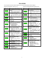
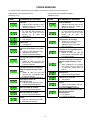
DK - INDHOLDSFORTEGNELSE: - Advarsel / Elektromagnetisk støjudstråling ...............................................................................5
- Produktprogram / Tilslutning og Ibrugtagning ..................................................................... 6 - 7
- Betjeningspanel .........................................................................................................................8
- Software .....................................................................................................................................9
- Tekniske data...........................................................................................................................10
- Fejlkoder...................................................................................................................................11
- Vedligeholdelse / Garantibetingelser.......................................................................................12
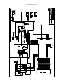
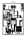
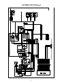
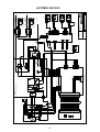
- Kredsløbsdiagram............................................................................................................85 - 88
UK - CONTENTS: - Warning / Electromagnetic emissions .....................................................................................13
- Product programme / Connection and operation............................................................ 14 - 15
- Control panel............................................................................................................................16
- Software ...................................................................................................................................17
- Technical data..........................................................................................................................18
- Error codes...............................................................................................................................19
- Maintenance / Warranty conditions.........................................................................................20
- Circuit diagram................................................................................................................. 85 - 88
D - INHALTSVERZEICHNIS: - Warnung / Elektromagnetische Störungen .............................................................................21
- Produktübersicht / Anschluß und Inbetriebnahme.......................................................... 22 - 23
- Bedienfeld ................................................................................................................................24
- Software ...................................................................................................................................25
- Technische Daten....................................................................................................................26
- Fehlerkoden .............................................................................................................................27
- Wartung / Garantiebedingungen .............................................................................................28
- Kreislaufdiagramme......................................................................................................... 85 - 88
F - TABLE DES MATIERES: - Avertissement / Emissions électomagnétiques.......................................................................29
- Programme du produit / Branchement et fonctionnement.............................................. 30 - 31
- Panneau de commande ..........................................................................................................32
- Software ...................................................................................................................................33
- Caractéristiques techniques ....................................................................................................34
- Codes erreurs ..........................................................................................................................35
- Entretien / Conditions de garantie ...........................................................................................36
- Schéma électrique ...........................................................................................................85 - 88
SE - INNEHÅLLSFÖRTECKNING: - Varning / Elektromagnetisk störfält..........................................................................................37
- Produktprogram / Anslutning och Igångsättning............................................................. 38 - 39
- Funktionspanel.........................................................................................................................40
- Software ...................................................................................................................................41
- Teknisk data.............................................................................................................................42
- Felkoder ...................................................................................................................................43
- Underhåll / Garantivillkor .........................................................................................................44
- Kretsloppsdiagram...........................................................................................................85 - 88
FI - SISÄLLYSLUETTELO: - Varoitus / Sähkömagneettiset häiriöt.......................................................................................45
- Tuoteohjelma / Kytkentä ja käyttö ................................................................................... 46 - 47
- Ohjauspaneeli ..........................................................................................................................48
- Software – Ohjelmat ................................................................................................................49
- Tekniset tiedot..........................................................................................................................50
- Virhekoodit ...............................................................................................................................51
- Huolto / Takuuehdot ................................................................................................................52
- Kytkentäkaavio................................................................................................................. 85 - 88
NL - INHOUD: - Waarschuwing / Elektromagnetische storingen......................................................................53
- Productprogramma / Aansluiting en bediening............................................................... 54 - 55
- Besturingspaneel .....................................................................................................................56
- Software ...................................................................................................................................57
- Technische gegevens..............................................................................................................58
- Foutcodes ................................................................................................................................59
- Onderhoud / Garantiebepalingen............................................................................................60
- Schema's.......................................................................................................................... 85 - 88
I - INDICE: - Attenzione/Emissioni elettromagnetiche .................................................................................61
- Programma del prodotto / Collegamenti ed uso ............................................................. 62 - 63
- Pannello di controllo.................................................................................................................64
- Software ...................................................................................................................................65
- Dati tecnici................................................................................................................................66
- Codici d’errore..........................................................................................................................67
- Manutenzione / Condizioni di garanzia ...................................................................................68
- Schema elettrico .............................................................................................................. 85 - 88
HU - TARTALOMJEGYZÉK: - Figyelmeztetés/elektromágneses hatás..................................................................................69
- Termékismertetés / Csatlakoztatás és üzembehelyezés ............................................... 70 - 71
- Automig vezérlés .....................................................................................................................72
- Szoftver ....................................................................................................................................73
- Műszaki adatok........................................................................................................................74
- Hibakódok ................................................................................................................................75
- Karbantartás / Garancia feltételek...........................................................................................76
- Kapcsolási rajz................................................................................................................. 85 - 88
PL – SPIS TREŚCI: - Ostrzeżenie / Emisje elektromagnetyczne..............................................................................77
- Opis produktu / Podłączenie i eksploatacja .................................................................... 78 - 79
- Panel sterowania .....................................................................................................................80
- Oprogramowanie .....................................................................................................................81
- Dane techniczne ......................................................................................................................82
- Kody błędów.............................................................................................................................83
- Konserwacja / Przepisy dotyczące gwarancji .........................................................................84
- Schemat połączeń........................................................................................................... 85 - 88


5
DANSK
Elektromagnetisk støjudstråling
Dette svejseudstyr, beregnet for professionel anvendelse, overhol-
der kravene i den europæiske standard EN/IEC60974-10 (Class A).
Standarden har til formål at sikre, at svejseudstyr ikke forstyrrer eller
bliver forstyrret af andet elektrisk udstyr som følge af elektromagne-
tisk støjudstråling. Da også lysbuen udsender støj, forudsætter an-
vendelse uden forstyrrelser, at der tages forholdsregler ved installa-
tion og anvendelse. Brugeren skal sikre, at andet elektrisk udstyr
i området ikke forstyrres.
Følgende skal tages i betragtning i det omgivne område:
1. Netkabler og signalkabler i svejseområdet, som er tilsluttet
andre elektriske apparater.
2. Radio- og fjernsynssendere og modtagere.
3. Computere og elektroniske styresystemer.
4. Sikkerhedskritisk udstyr, f.eks. overvågning og processtyring.
5. Brugere af pacemakere og høreapparater.
6. Udstyr som anvendes til kalibrering og måling.
7. Tidspunkt på dagen hvor svejsning og andre aktiviteter, afhæn-
gig af elektrisk udstyr, foregår.
8. Bygningers struktur og anvendelse.
Hvis svejseudstyret anvendes i boligområder kan det være nød-
vendigt at tage særlige forholdsregler (f.eks. information om midler-
tidigt svejsearbejde).
Metoder til minimering af forstyrrelser:
1. Undgå anvendelse af udstyr, som kan blive forstyrret.
2. Anvend korte svejsekabler.
3. Læg plus- og minuskabel tæt på hinanden.
4. Placer svejsekablerne på gulvniveau.
5. Fjern signalkabler i svejseområdet fra netkabler.
6. Beskyt signalkabler i svejseområdet f.eks med skærmning.
7. Benyt isoleret netforsyning til følsomme apparater.
8. Overvej skærmning af den komplette svejseinstallation.
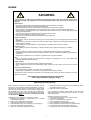
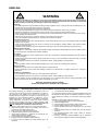
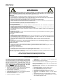
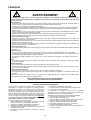
ADVARSEL
Lysbuesvejsning og -skæring kan ved forkert brug være farligt for såvel bruger som omgivelser. Derfor må ud-
styret kun anvendes under iagttagelse af relevante sikkerhedsforskrifter. Især skal man være opmærksom på
følgende:
Elektrisk stød
- Svejseudstyret skal installeres forskriftsmæssigt. Maskinen skal jordforbindes via netkablet.
- Sørg for regelmæssig kontrol af maskinens sikkerhedstilstand.
- Beskadiges kabler og isoleringer, skal arbejdet omgående afbrydes og reparation foretages.
- Kontrol, reparation og vedligeholdelse af udstyret skal foretages af en person med den fornødne faglige indsigt.
- Undgå berøring af spændingsførende dele i svejsekredsen eller elektroder med bare hænder. Brug aldrig defekte
eller fugtige svejsehandsker.
- Isolér Dem selv fra jorden og svejseemnet (brug f.eks fodtøj med gummisål).
- Brug en sikker arbejdsstilling (undgå f.eks. fare for fald).
- Følg reglerne for "Svejsning under særlige arbejdsforhold" (Arbejdstilsynet).
Svejse- og skærelys
- Beskyt øjnene, idet selv en kortvarig påvirkning kan give varige skader på synet. Brug svejsehjelm med foreskrevet
filtertæthed.
- Beskyt kroppen mod lyset fra lysbuen, idet huden kan tage skade af stråling. Brug beskyttende beklædning, der
dækker alle dele af kroppen.
- Arbejdsstedet bør om muligt afskærmes, og andre personer i området advares mod lyset fra lysbuen.
Svejserøg og gas
- Røg og gasser, som dannes ved svejsning, er farlige at indånde. Sørg for passende udsugning og ventilation.
Brandfare
- Stråling og gnister fra lysbuen kan forårsage brand. Letantændelige genstande fjernes fra svejsepladsen.
- Arbejdstøjet skal være sikret mod gnister og sprøjt fra lysbuen. Brug evt. brandsikkert forklæde og pas på åbenstå-
ende lommer.
- Særlige regler er gældende for rum med brand- og eksplosionsfare. Følg disse forskrifter.
Støj
- Lysbuen frembringer akustisk støj, og støjniveauet er betinget af svejseopgaven. Det vil i visse tilfælde være
nødvendigt at beskytte sig med høreværn.
Farlige områder
- Stik ikke fingrene ind i de roterende tandhjul i trådfremføringsenheden.
- Særlig forsigtighed skal udvises når svejsearbejdet foregår i lukkede rum eller i højder hvor der er fare for at falde
ned.
Placering af svejsemaskinen
- Placer svejsemaskinen således, at der ikke er risiko for, at den vælter.
- Særlige regler er gældende for rum med brand- og eksplosionsfare. Følg disse forskrifter.
Anvendelse af maskinen til andre formål end det, den er beregnet til (f.eks. optøning af vandrør) frarådes og sker i givet
tilfælde på eget ansvar.
Gennemlæs denne betjeningsvejledning omhyggeligt,
inden udstyret installeres og tages i brug!

6
PRODUKTPROGRAM
220/270A svejsemaskine til MIG/MAG svejsning. Ma-
skinen er luftkølet og leveres med indbygget trådfrem-
føring med 4-hjuls trissetræk.
Svejseslanger og kabler
Til maskinerne kan MIGATRONIC fra sit produkt-
program levere MIG/MAG-slanger, returstrømkabler,
mellemkabler, sliddele mm.
Tilbehørsprogram
Kontakt nærmeste forhandler for oplysninger om
AUTOMIG tilbehørsprogram.
Bortskaf produktet i overensstemmelse med
gældende regler og forskrifter.
www.migatronic.com/goto/weee
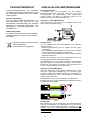
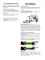
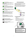
TILSLUTNING OG
IBRUGTAGNING
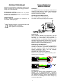
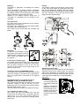
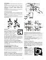
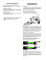
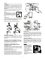
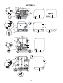
Installation
I det følgende beskrives, hvorledes de enkelte dele af
maskinen kobles sammen, sluttes til forsyningsnettet
og tilsluttes gasforsyningen mm. Tallene i parentes
henviser til figurerne i afsnittet.
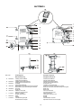
Udpakning af AUTOMIG 223i/273i
Efter udpakning og før ibrugtagning af
AUTOMIG 223i/273i gøres følgende (se skitse)
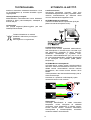
Nettilslutning
Inden maskinen tilkobles forsyningsnettet, skal det
kontrolleres, at den er beregnet til den aktuelle net-
spænding, og at forsikringen i forsyningsnettet er i
overensstemmelse med typeskiltet. Netkablet (1) skal
tilsluttes 3-faset vekselstrøm 50 eller 60 Hz og beskyt-
telsesjord. Rækkefølgen af faserne er uden betydning.
Maskinen tændes med hovedafbryderen (2).
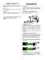
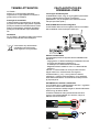
Nettilslutning AUTOMIG Boost
AUTOMIG Boost kan tilsluttes en-faset netspænding i
området fra 200-240V og trefaset netspænding fra
200-440V. Maskinen indstiller sig automatisk til den
aktuelle netspænding uden at der skal foretages
omkobling indvendig i maskinen.
Netstikket skal monteres af en elektriker.
Maskinen er udstyret med et firleder netkabel og skal
monteres som vist nedenfor:
Konfigurering
Hvis maskinen udstyres med svejsebrænder og svej-
sekabler, der er underdimensioneret i forhold til
svejsemaskinens specifikationer f.eks. med hensyn til
den tilladelige belastning, påtager MIGATRONIC sig
intet ansvar for beskadigelse af kabler, slanger og
eventuelle følgeskader.

7
Advarsel
Tilslutning til generator, kan medføre at svejsemaski-
nen ødelægges.
Generatorer kan i forbindelse med tilslutning til en
svejsemaskine afgive store spændingspulser som vir-
ker ødelæggende på svejsemaskinen. Kun frekvens-
og spændingsstabile generatorer af asynkron-typen
må anvendes.
Defekter som opstår på svejsemaskinen, som følge af
tilslutning til generator er ikke omfattet af garantien.
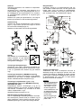
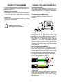
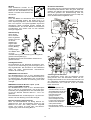
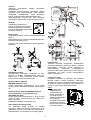
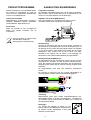
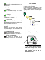
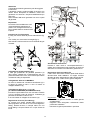
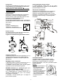
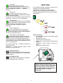
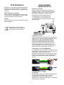
Løfteanvisning
Løfteøjet kan bruges på sækkevogn til løft med kran
(figur 1). Vogn med 4 hjul kan kun bruges til manuel
løft ved at løfte i håndtaget (figur 2).
Maskinen må ikke løftes med monteret gasflaske!
Vigtigt!
Når stelkabel og svejsebrænder til-
sluttes maskinen, er god elektrisk
kontakt nødvendig, for at undgå at
stik og kabler ødelægges.
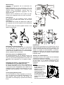
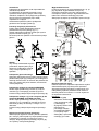
Tilslutning af beskyttelsesgas
Gasslangen, som udgår fra bagsiden af maskinen (3),
tilsluttes en gasforsyning med en trykreduktion til max.
6 bar. En gasflaske kan fikseres bag på eventuel
vogn.
Tilslutning af brænder for MIG/MAG-svejsning
Svejseslangen trykkes i ZA-koblingen (4), og spænde-
omløberen (5) på enden af slangen spændes med
hånden. Stelkablet tilsluttes svejseminus (6).
Tilslutning af svejsebrænder 1 (pos. 7) og
svejsebrænder 2 (pos. 8) for MIG/MAG-svejsning
(AUTOMIG 223i DUO)
Svejseslangen trykkes i ZA-koblingen (7 og 8), og
spændeomløberen (5) på enden af slangen spændes
med hånden. Omskifteren (9) anvendes til at skifte
mellem svejsebrænder 1 og 2.
Stelkablet tilsluttes svejseminus (10).
Brænderregulering (Dialog brænder)
Hvis en svejseslange med Dialog brænder anvendes,
kan strømstyrken justeres både på maskinen og på
dialog brænderen. Denne funktion kan ikke slås fra.
Brænderreguleringen er passiv uden Dialog brænder.
Rangerfunktion
Funktionen bruges til at rangere/fremføre tråd evt.
efter trådskift. Tråden føres frem, når den grønne tast
holdes nede, mens der tastes på brændertasten.
Trådførselen fortsætter, selvom den grønne tast slip-
pes, og stopper først, når brændertasten slippes.
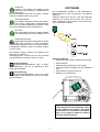
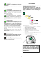
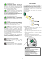
Justering af trådbremse
Trådbremsen skal sikre at trådspolen bremses til-
strækkelig hurtigt når svejsningen ophører. Den nød-
vendige bremsekraft er afhængig af vægten på tråd-
rullen, og den maksimale trådhastighed der anvendes.
Et bremsemoment på 1,5-2,0 Nm vil være fyldest-
gørende til de fleste anvendelser.
Justering:
- Afmonter drejeknappen
ved at stikke en tynd
skruetrækker ind bag-
ved knappen og ryk
derefter knappen ud.
- Juster trådbremsen ved
at spænde eller løsne
låsemøtrikken på tråd-
navets aksel
- Monter knappen igen
ved at trykke den på
plads i rillen.

8
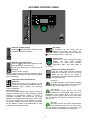
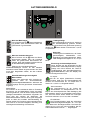
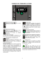
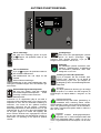
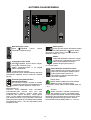
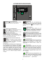
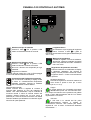
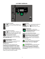
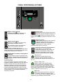
AUTOMIG BETJENINGSPANEL
Valg af materialetype
Her vælges først materialetype ved at trykke
på -knappen, indtil lysdioden tændes ud for
det ønskede valg.
Valg af tråddiameter
Tryk på -knappen indtil lysdioden tændes
ud for den ønskede tråddiameter.
Ikke alle tråddiametre kan vælges for alle
materialer.
Reset til fabriksindstillinger:
Fabriksindstillinger for den valgte tråddiameter gen-
indlæses ved at holde knappen inde, indtil indikatoren
giver et kort blink.
Strøm/trådhastighed/materialetykkelse
Når maskinen ikke svejser, vises den ind-
stillede strøm/trådhastighed/materialetykkel-
se. Under svejsning vises den målte strøm.
Materialetykkelse:
Funktionen er en vejledende hjælp til at indstille strøm-
men ud fra materialetykkelsen (i mm). Når en materia-
letykkelse er valgt, sker en automatisk indstilling af
strømmen, der svarer til den pågældende materiale-
tykkelse. Strømmen kan frit justeres efterfølgende.
Materialetykkelsesfunktionen skal betragtes som et
godt udgangspunkt til valg af den rette strømindstilling
til en given opgave. Det vil for næsten alle opgaver,
hvor denne funktion benyttes som udgangspunkt,
være nødvendigt med efterfølgende trimning af både
strøm og spænding for at opnå et optimalt resultat.
Lysbuelængde
Efter behov kan lysbuelængden justeres
ved at trimme spændingen. Under svejs-
ning vises målt spænding. Tryk på -knappen og trim
fra –9,9 til +9,9.
Drejeknap
På drejeknappen justeres svejsestrøm,
trådhastighed, materialetykkelse, lysbue-
længde og sekundære parametre. Maks.
trådhastighed er 15,0 m/min.
Indstilling af sekundære parametre
Tryk på knappen indtil den ønskede para-
meter vises i displayet. For at vende tilbage til
normalvisning tastes kort på knappen for lys-
buelængde eller strøm/trådhastighed/mate-
rialetykkelse.
Arc adjust:
Arc adjust (elektronisk drossel) gør det muligt
at justere, hvor hurtigt der skal reageres på
kortslutninger. Arc adjust kan indstilles i trin fra –5,0 til
+5,0.
Gasforstrømningstid:
Gasforstrømning skal sikre gasdækning af
svejsestedet, før svejsningen begynder. Gas-
forstrømningstiden er tiden, fra brændertasten aktive-
res, og gasstrømningen begynder, til trådfremføringen
startes. Gasforstrømningstiden indstilles imellem 0,0
sek. og 10,0 sek.
Krybestart:
Krybestart forbedrer tændingsegenskaber. Her
indstilles, hvilken hastighed tråden skal starte
med. Hastigheden indstilles mellem 1,5-15,0 m/min.
Krybestartsfunktionen frakobles, når der vises - - - .

9
Hotstart-tid:
Hotstart er en funktion, som hjælper med at
skabe den rette temperatur i smeltebadet ved
start af svejsningen.
Hotstart-tid bestemmer den tid der svejses i hotstart.
Tiden kan indstilles imellem 0 og 10 sek
Strømsænkningstid:
Her indstilles varigheden af strømsænkningen.
Ved tastning påbegyndes strømsænknings-
fasen, hvor der laves kraterfyldning. Strømmen sæn-
kes fra den indstillede strøm til stopstrømmen.
Burn back:
Burn back funktionen sikrer, at tråden brænder
fri fra smeltebadet. Burn back indstilles i trin fra
1 til 30.
Gasefterstrømningstid:
Gasefterstrømning sikrer beskyttelse af smelte-
badet efter svejsning og køler brænderen.
Gasefterstrømningstiden er tiden, fra lysbuen slukker,
til gastilførslen afbrydes. Tiden kan indstilles imellem
0,0 og 10,0 sek.
Når maskinen slukkes, gemmes de indstillede para-
metre internt i maskinen.
Samtidigt gemmes nummeret på det sidst anvendte
program således, at maskinen starter op i dette.
Svejsespænding
Svejsespændingsindikatoren lyser af sikker-
hedshensyn, hvis der er spænding på elek-
troden eller brænderen.
Overophedning
Overophedningsindikatoren lyser, hvis svejs-
ningen er blev afbrudt på grund af overophed-
ning af maskinen.
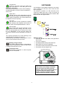
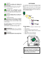
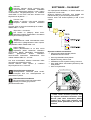
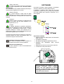
SOFTWARE
Hvis kontrolboksen udskiftes er det nødvendigt at
lægge software ind i den nye boks igen, ved hjælp af
et SD kort.
Softwaren ligger på et SD kort, som skal indeholde
mapperne og én eller flere af filerne som vist her-
under. Mappenavne skal skrives med STORE bog-
staver og må ikke omdøbes.
Software indlæsning
• Indsæt SD-kortet i slidsen i maskinens højre side.
• Tænd maskinen.
• Displayet blinker kortvarigt med tre streger.
• Vent indtil maskinens display viser den indstillede
strøm.
• Sluk maskinen og tag SD-kortet ud
• Maskinen er nu klar til brug.
* Alle maskinens brugerindstillinger slettes
når der indlæses nyt software. Tag derfor
altid SD-kortet ud af maskinen efter opdate-
ringen, for at undgå at softwaren indlæses
hver gang maskinen tændes.

10
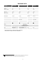
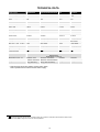
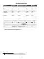
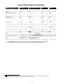
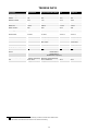
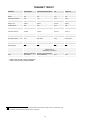
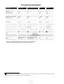
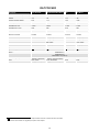
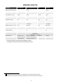
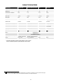
TEKNISKE DATA
Strømkilde: AUTOMIG
223i/223i DUO
AUTOMIG
223i Boost/223i DUO Boost
AUTOMIG
273i
AUTOMIG
273i Boost
Netspænding (50Hz-60Hz) 3 x 400V 3x230/400V ±15% 3x400 V ±15% 3x230/400 V ±15%
Netspænding (50Hz-60Hz) 1x230V 1x230V
Netsikring 10A 16A 10 A 16A
Netstrøm, effektiv 6,0A 7,1A 7,6 A 10,5A
Netstrøm, max. 10,1A 29,9A 13,2 A 42,0A
Effekt, (100%) 4,2kVA 1,6kVA 5,3 kVA 2,4kVA
Effekt, max 7,0kVA 6,9kVA 9,1 kVA 9,7kVA
Effekt, tomgang 20W 30W 20 W 30W
Virkningsgrad 0,90 0,84 0,88 0,84
Power faktor 0,87 0,99 0,93 0,99
Strømområde 10-220A 10-220A 10-270 A 10-270 A
Intermittens 100% v/20°C 180A 115A (140A)* 230 A 150A (180A)*
Intermittens 60% v/20°C 220A 150A (175A)* 245 A 180A (200A)*
Intermittens 100% v/40°C 145A 70A (81A)* 175 A 95A (107A)*
Intermittens 60% v/40°C 170A 86A (108A)* 195 A 110A (126A)*
Intermittens max. v/40°C 30% 14% (16%)* 25 % 12% (13%)*
Tomgangsspænding 52V 52V 52 V 52 V
1Anvendelsesklasse
S
S
S
S
2Beskyttelsesklasse IP 23 IP 23 IP 23 IP 23
Normer EN/IEC60974-1
EN/IEC60974-5
EN/IEC60974-10 (Class A)
Dimensioner (hxbxl) cm 55x25x64 (223i)
96x57x87 (223i DUO) 55x25x64 (223i Boost)
96x57x87 (223i DUO Boost) 55x25x64 55x25x64
Vægt 25 kg (223i)
54 kg (223i DUO) 27 kg (223i Boost)
56 kg (223i DUO Boost) 26 kg 28 kg
* Data for Boost-version er angivet ved 1x230V netspænding
Data i parentes er angivet ved 3x400V netspænding
1
S
Maskinen opfylder de krav der stilles under anvendelse i områder med forøget risiko for elektrisk chok
2
Maskinen må anvendes udendørs, idet den opfylder kravene til beskyttelsesklasse IP23.”

11
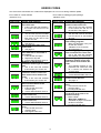
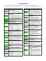
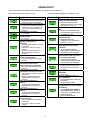
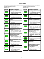
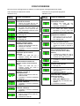
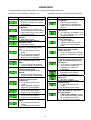
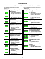
FEJLKODER
Hvis der opstår en fejl under software indlæsning vil en af nedenstående fejlkoder blinke i displayet.
Fejlkoder til Styresoftware 10001501.xx.cry
Fejlkode Årsag og udbedring
Der er ingen software i kontrol-
boksen.
• Sæt et SD kort med software i
boksen og tænd maskinen.
SD kortet er ikke formateret.
• Formater SD kortet i en PC,
som FAT og læg filerne ned på
kortet. Eller anvend et andet SD
kort.
SD kortet indeholder ingen
software.
• Se side 9.
SD kortet har flere filer med
samme navn.
• Se side 9.
Kontrolboksen har forsøgt at
indlæse flere data end den kan
have i hukommelsen.
1. Indlæs SD kortet igen.
2. Udskift SD kortet.
3. Tilkald MIGATRONIC Service.
Software på SD kortet er låst til
en anden type kontrolboks.
• Anvend et SD kort med
software som passer til din type
kontrolboks.
Software på SD kortet er låst til
en anden kontrolboks med et
andet serienummer/stregkode.
• Anvend et SD kort med
software som passer til din
kontrolboks.
Den interne kopibeskyttelse til-
lader ikke adgang til mikro-
processoren.
1. Indlæs SD kortet i maskinen
igen.
2. Tilkald MIGATRONIC Service.
Kontrolboksens hukommelses-
kreds er defekt.
• Tilkald MIGATRONIC Service.
Kontrolboksens
hukommelseskreds er defekt.
• Tilkald MIGATRONIC Service.
Den indlæste fil 100015xx.xx.cry
er fejlbehæftet.
1. Indlæs SD kortet igen
2. Udskift SD kortet.
Fejlkoder til Svejseprogrampakke 10646001.xx.bin
Fejlkode Årsag og udbedring
Der er ingen svejseprogrammer i
kontrolboksen.
• Sæt et SD kort med software i
boksen og tænd maskinen. Se
side 9.
SD kortet er ikke formateret.
• Formater SD kortet i en PC,
som FAT. Eller anvend et andet
SD kort.
Det er kun muligt at have én fil
med svejseprogrammer.
• Sørg for at der kun ligger én fil
med nummeret 106460xx-xx.bin
på SD kortet. Se side 9.
Den svejseprogrampakke du
forsøger at indlæse passer ikke
til denne kontrolboks.
• Anvend et SD kort med
software som passer til din
kontrolboks.
Den svejseprogrampakke du
forsøger at indlæse, er låst til en
kontrolboks med et andet serie-
nummer.
• Din softwarepakke er kopi-
beskyttet og forsøges anvendt
på en kontrolboks der ikke er
købt licens til.
Kontrolboksen er defekt.
• Tilkald MIGATRONIC Service.
Filen 106460xx.xx.bin mangler på
SD kortet.
• Se side 9.
Den indlæste file 106460xx.xx.bin
er fejlbehæftet.
1. Indlæs SD kortet igen.
2. Udskift SD kortet.
Omega mappen med filerne fin-
des ikke på kortet eller er place-
ret det forkerte sted.
1. Opret mapperne
MIGA_SW / OMEGA som
beskrevet på side 9 og placér
filerne heri.
2. Udskift SD kortet.

12
VEDLIGEHOLDELSE
Maskinen skal regelmæssigt vedligeholdes og rengø-
res for at undgå funktionsfejl og sikre driftssikkerhed.
Manglende vedligeholdelse har indflydelse på drifts-
sikkerheden og resulterer i bortfald af garanti.
ADVARSEL!
Service- og rengøringsarbejder på åbnede svejse-
maskiner må kun udføres af kvalificeret personale.
Anlægget skal frakobles forsyningsnettet (netstik
trækkes ud!). Vent ca. 5 minutter før vedligeholdel-
se og reparation, da alle kondensatorer skal afla-
des da der er risiko for stød.
Trådrum
- Rengør trådrummet med trykluft og efterse tråd-
trissernes spor og tænder for slitage, efter behov.
Strømkilde
- Strømkildens ventilatorvinge og køletunnel skal
rengøres med trykluft efter behov.
- Der skal mindst én gang årligt gennemføres efter-
syn og rengøring af kvalificeret servicetekniker.
GARANTIBETINGELSER
Migatronic svejsemaskiner kvalitetskontrolleres
løbende i hele produktionsforløbet og afprøves som
samlede enheder gennem omhyggelig, kvalitetssikret
funktions- og sluttest.
Migatronic yder 24 måneders garanti, svarende til
1600 lysbuetimer, på alle typer Migatronic
svejsemaskiner, hvis svejsemaskinen registreres.
Registrering skal foretages på internetadressen:
www.migatronic.com/warranty. Som bevis for
registreringen gælder registreringsbeviset, der
fremsendes pr. e-mail. Den originale faktura samt
registreringsbeviset er købers dokumentation for, at
svejsemaskinen er omfattet af en 24 måneders
garanti.
Såfremt registrering ikke foretages, er standard
garantiperioden 12 måneder for nye svejsemaskiner,
regnet fra dato for fakturering til slutkunde. Den
originale faktura er dokumentation for garantiperioden.
Migatronic yder garanti i henhold til gældende
garantibetingelser ved at udbedre mangler eller fejl
ved svejsemaskiner, der påviseligt inden for
garantiperioden måtte skyldes materiale- eller
produktionsfejl.
Der ydes som hovedregel ikke garanti på svejse-
slanger, da disse anses som sliddele; dog vil fejl og
mangler, som opstår inden for 4 uger efter
ibrugtagning og som skyldes materiale- eller
produktionsfejl, blive betragtet som
garantireklamation.
Enhver form for transport i forbindelse med en
garantireklamation er ikke omfattet af Migatronics
garantiydelse og vil derfor ske for købers regning og
risiko.
I øvrigt henvises til Migatronic gældende
garantibetingelser som er tilgængelig på:
www.migatronic.com/warranty.

13
ENGLISH
Electromagnetic emissions and the radiation of electromagnetic disturbances
This welding equipment for industrial and professional use is in
conformity with the European Standard EN/IEC60974-10 (Class A).
The purpose of this standard is to prevent the occurrence of
situations where the equipment is disturbed or is itself the source of
disturbance in other electrical equipment or appliances. The arc
radiates disturbances, and therefore, a trouble-free performance
without disturbances or disruption, requires that certain measures
are taken when installing and using the welding equipment. The
user must ensure that the operation of the machine does not
occasion disturbances of the above mentioned nature.
The following shall be taken into account in the surrounding area:
1. Supply and signalling cables in the welding area which are
connected to other electrical equipment.
2. Radio or television transmitters and receivers.
3. Computers and any electrical control equipment.
4. Critical safety equipment e.g. electrically or electronically con-
trolled guards or protective systems.
5. Users of pacemakers and hearing aids etc.
6. Equipment used for calibration and measurement.
7. The time of day that welding and other activities are to be
carried out.
8. The structure and use of buildings.
If the welding equipment is used in a domestic establishment it may
be necessary to take special and additional precautions in order to
prevent problems of emission (e.g. information of temporary welding
work).
Methods of reducing electromagnetic emissions:
1. Avoid using equipment which is able to be disturbed.
2. Use short welding cables.
3. Place the positive and the negative cables close together.
4. Place the welding cables at or close to floor level.
5. Remove signalling cables in the welding area from the supply
cables.
6. Protect signalling cables in the welding area, e.g. with selective
screening.
7. Use separately-insulated mains supply cables for sensitive
electronic equipment.
8. Screening of the entire welding installation may be considered
under special circumstances and for special applications.
WARNING
Arc welding and cutting can be dangerous to the user, people working nearby, and the surroundings if the equipment
is handled or used incorrectly. Therefore, the equipment must only be used under the strict observance of all relevant
safety instructions. In particular, your attention is drawn to the following:
Electricity
- The welding equipment must be installed according to safety regulations and by a properly trained and qualified person. The
machine must be connected to earth through the mains cable.
- Make sure that the welding equipment is correctly maintained.
- In the case of damaged cables or insulation, work must be stopped immediately in order to carry out repairs.
- Repairs and maintenance of the equipment must be carried out by a properly trained and qualified person.
- Avoid all contact with live components in the welding circuit and with electrodes and wires if you have bare hands. Always
use dry welding gloves without holes.
- Make sure that you are properly and safely earthed (e.g use shoes with rubber sole).
- Use a safe and stable working position (e.g. avoid any risk of accidents by falling).
Light and heat emissions
- Protect the eyes as even a short-term exposure can cause lasting damage to the eyes. Use a welding helmet with suitable
radiation protection glass.
- Protect the body against the light from the arc as the skin can be damaged by welding radiation. Use protective clothes,
covering all parts of the body.
- The place of work should be screened, if possible, and other persons in the area warned against the light from the arc.
Welding smoke and gases
- The breathing in of the smoke and gases emitted during welding is damaging to health. Make sure that any exhaust systems
are working properly and that there is sufficient ventilation.
Fire hazard
- Radiation and sparks from the arc represent a fire hazard. As a consequence, combustible materials must be removed from
the place of welding.
- Working clothing should also be secure against sparks from the arc (e.g. use a fire-resistant material and watch out for folds
and open pockets).
- Special regulations exist for rooms with fire- and explosion hazard. These regulations must be followed.
Noise
- The arc generates acoustic noise according to welding task. In some cases, use of hearing aids is necessary.
Dangerous areas
- Fingers must not be stuck into the rotating gear wheels in the wire feed unit.
- Special consideration must be taken when welding is carried out in closed areas or in heights where there is a danger of
falling down.
Positioning of the machine
- Place the welding machine so there is no risk that the machine will tip over.
- Special regulations exist for rooms with fire- and explosion hazard. These regulations must be followed.
Use of the machine for other purposes than it is designed for (e.g. to unfreeze water pipes) is strongly deprecrated. If the
occasion should arise this will be carried out without responsibility on our part.
Read this instruction manual carefully
before the equipment is installed and in operation

14
PRODUCT PROGRAMME
220/270A welding machine for MIG/MAG welding. The
machine is air-cooled and is supplied with built-in wire
feed with 4-roll drive.
Welding hoses and cables
MIGATRONIC’s product range can provide MIG/MAG
torches and hoses, return current cables, intermediary
cables and wear parts etc.
Accessories
Please contact your Migatronic dealer for further
information on accessories.
Dispose of the product according to local
standards and regulations.
www.migatronic.com/goto/weee
CONNECTION AND OPERATION
Permissible installation
The following sections describe how the machine is
made ready for use and then connected to mains
supply, gas supply etc. The numbers in parentheses
refer to the illustrations in this paragraph.
Unpacking the AUTOMIG 223i/273i
After unpacking and prior to using the
AUTOMIG 223i/273i, proceed as follows (see
drawing):
Mains connection
Before connecting the power source to the mains
supply, ensure that the power source is of the same
voltage as the mains voltage provided and that the
fuse in the mains supply is of the correct size. The
mains cable (1) of the power source must be
connected to the correct three-phase alternating
current (AC) supply of 50 Hz or 60 Hz and with earth
connection. The sequence of the phases is not of
significance. The power source is switched on with the
mains switch (2).
Mains connection AUTOMIG Boost
The AUTOMIG Boost can be connected to a single-
phase mains supply from 200-240V and three-phase
mains supply from 200V-440V. The machine auto-
matically adjusts itself to the present mains voltage
where no decoupling inside the machine is required.
The mains plug must be mounted by an electrician.
The machine is equipped with a four-wire mains cable
and must be mounted as shown below:
Configuration
MIGATRONIC disclaims all responsibility for damaged
cables and other damages related to welding with
undersized welding torch and welding cables
measured by welding specifications e.g. in relation to
permissible load.

15
Warning
Connection to generators can damage the welding
machine.
When connected to a welding machine, generators
can produce large voltage pulses, which can damage
the welding machine. Use only frequency and voltage
stable generators of the asynchronous type.
Defects on the welding machine arising due to
connection of a generator are not included in the
guarantee.
Lift instructions
The lifting points at the sack barrow can be used for
lifting with a crane (figure 1).
The trolley with 4 wheels can only be lifted manually
by lifting it in the handle (figure 2).
The machine must not be lifted with mounted gas
bottle!
Important!
In order to avoid damage to plugs
and cables, good electric contact is
required when connecting the work
return cable and welding torch to
the machine.
Connection of shielding gas
The shielding gas hose is fitted to the back panel of
the power source (3) and is connected to a gas supply
with a pressure reduction to max. 6 bar. One gas
cylinder can be mounted on the bottle carrier on the
back of a trolley if any.
Connection of torch for MIG/MAG welding
The welding hose assembly is pushed into the central
connector coupling (4) and the nut (5) is tightened by
hand. The return lead is connected to the negative
pole (6).
Connection of torch 1 (7) and torch 2 (8) for
MIG/MAG-welding (AUTOMIG 223i DUO)
The welding hose assembly is pushed into the central
connector coupling (7 and 8), and the nut (5) is
tightened by hand. The reverser (9) is used for change
between welding torch 1 and 2.
The return lead is connected to the negative pole (10).
Torch adjustment (Dialog torch)
The current size can be adjusted both from the
machine and the welding torch if a welding hose with
dialog torch is in use. This function cannot be
disconnected. The torch adjustment is passive without
Dialog torch.
Inching
The function is used for wire inching e.g. after change
of wire. Wire inching starts by pressing the green key
pad and simultaneously triggering the torch trigger.
Wire inching continues even though the green key pad
has been released. It does not stop until the torch
trigger has been released again.
Adjustment of wire brake
The wire brake must ensure that the wire reel brakes
sufficiently quickly when welding stops. The required
brake force is depending on the weight of the wire reel
and the maximum wire feed speed. A brake torque of
1.5-2.0 Nm will be satisfactory for most applications.
Adjustment:
- Dismount the control
knob by placing a thin
screw driver behind the
knob and thereafter pull
it out
- Adjust the wire brake by
fastening or loosening
the self-locking nut on
the axle of the wire hub
- Remount the knob by
pressing it back into the
groove.

16
AUTOMIG CONTROL PANEL
Selection of material type
Press the -key pad until the indicator for the
required material is switched on.
Selection of wire dimension
Press the -key pad until the indicator for the
required diameter is switched on.
Not all wire dimensions can be used for all
materials.
Reset to factory settings:
Factory settings for the selected wire dimension will be
reloaded when pressing the key pad until the indicator
gives a short flash.
Current/wire feed speed/material
thickness:
When the machine is not welding, the set
current/ wire feed speed/material dimension is
displayed. During welding the measured
current is displayed.
Material thickness:
The function helps adjusting the current according to
material thickness (in mm). When selecting material
thickness an automatically setting of current is
calculated. Thereafter, the current can be further
adjusted. The material thickness function can be seen
as a good starting point in the selection of correct
current and voltage. A trimming of these parameters
will be required in almost every welding task in order
to obtain the most optimum result.
Arc length
If necessary, the arc length can be
adjusted by trimming the voltage. The
measured voltage is shown during welding. Press the
-key pad and adjust from –9,9 to +9,9.
Control knob
This knob is used for adjusting welding
current, wire feed speed, material
thickness, arc length and secondary
parameters. Max. wire feed speed is
15.0 m/min.
Setting of secondary parameters
Press the control knob until the requested
parameter is displayed. To return to normal
display the key pad for arc length or
current/wire feed speed/material thickness is
to be pressed briefly.
Arc adjust:
Arc-adjust (electronic choke) makes it possible
to adjust the speed of reaction to short-circuits.
Arc-adjust can be set in steps from –5.0 to +5.0.
Gas pre-flow:
Gas pre-flow ensures that the arc is fully
protected from atmosphere before an arc is
established. Gas pre-flow time is the time from
activating the torch trigger until the wire feed starts.
The gas pre-flow time can be set between 0.0 sec.
and 10.0 sec.
Soft start:
Soft start improves the ignition characteristics.
Here speed with which the wire shall start is
set. The speed is set between 1.5-15.0 m/min. The
soft start function is disengaged when displaying - - - .

17
Hot-start time :
Hotstart is a function which help creating the
right temperature in the weld pool at the
beginning of the welding.
Hot-start time determines the time in which welding in
hot-start takes place. The time can be set between 0
and 10 secs
Slope-down:
The time of the current slope-down is set. By
activating the trigger, the slope down begins in
order to make a crater filling. The current reduces from
the adjusted current to stop amp.
Burn back:
The burn back function prevents the welding
wire sticking to the workpiece at the end of a
weld. Burn-back can be adjusted between 1 and 30.
Gas post-flow:
Gas post-flow time ensures protection of the
molten pool after welding and cools off the
torch. The gas post-flow time is the time from which
the arc extinguishes to the gas flow being dis-
connected. The time can be set between 0.0 and 10.0
sec.
The adjusted parameters are saved internally in the
machine when the machine is turned off.
Simultaneously, the number of the program in use is
saved so the machine will start up in this.
Welding voltage indicator
The welding voltage indicator is illuminated for
reasons of safety and in order to show if there
is voltage at the electrode or torch.
Temperature fault
The indicator is switched on, when the power
source is overheated.
SOFTWARE
It is necessary to read software inside the new control
unit by means of a SD card, if the control unit has
been exchanged.
The software is placed on a SD card which must
contain the folders and one or more of the files as
shown below. The folder names must be saved in BIG
letters and with the original names.
Software reading
• Insert the SD-card in the slide in the right side of
the machine.
• Turn on the machine.
• The display flashes shortly with three lines.
• Wait until the set current is displayed.
• Turn off the machine and remove the SD card.
• The machine is now ready for use.
* All machine user settings are deleted
when new software has been inserted.
Therefore, always remove the SD-card from
the machine after the software update.
Thereby, continuous software update is
avoid each time the machine is turned on.

18
TECHNICAL DATA
Power source: AUTOMIG
223i/223i DUO
AUTOMIG
223i Boost/223i DUO Boost
AUTOMIG
273i
AUTOMIG
273i Boost
Mains voltage (50Hz-60Hz) 3x400V ±15% 3x230/400V ±15% 3x400 V ±15% 3x230/400 V
±15%
Mains voltage (50Hz-60Hz) 1x230V 1x230V
Fuse 10A 16A 10 A 16A
Mains current, effective 6.0A 7.1A 7.6 A 10.5A
Mains current, max. 10.1A 29.9A 13.2 A 42.0A
Power, (100%) 4.2kVA 1.6kVA 5.3 kVA 2.4kVA
Power, max 7.0kVA 6.9kVA 9.1 kVA 9.7kVA
Open circuit power 20W 30W 20 W 30W
Efficiency 0.90 0.84 0.88 0.84
Efficiency factor 0.87 0.99 0.93 0.99
Current range 10-220A 10-220A 10-270 A 10-270 A
Duty cycle 100% at 20°C 180A 115A (140A)* 230 A 150A (180A)*
Duty cycle 60% at 20°C 220A 150A (175A)* 245 A 180A (200A)*
Duty cycle 100% at 40°C 145A 70A (81A)* 175 A 95A (107A)*
Duty cycle 60% at 40°C 170A 86A (108A)* 195 A 110A (126A)*
Duty cycle max. at 40°C 30% 14% (16%)* 25 % 12% (13%)*
Open circuit voltage 52V 52V 52 V 52 V
1Sphere of application
S
S
S
S
2 Protection class IP 23 IP 23 IP 23 IP 23
Norm EN/IEC60974-1
EN/IEC60974-5
EN/IEC60974-10 (Class A)
Dimensions (hxwxl) cm 55x25x64 (223i)
96x57x87 (223i DUO) 55x25x64 (223i Boost)
96x57x87 (223i DUO Boost) 55x25x64 55x25x64
Weight 25 kg (223i)
54 kg (223i DUO) 27 kg (223i Boost)
56 kg (223i DUO Boost) 26 kg 28 kg
* Data for Boost-version are stated at 1x230V mains supply
Data in parenthesis are stated at 3x400V mains supply
1
S
This machine meets the demand made for machines which are to operate in areas with increased hazard of electric chocks
2 Equipment marked IP23 is designed for indoor and outdoor applications

19
ERROR CODES
One of the below mentioned error codes will be displayed if an error occurs during software update.
Error codes for control software
10001501.xx.cry
Error code Cause and solution
There is no software present in
the control unit.
• Insert a SD card with software in
the control unit and turn on the
machine.
SD card is not formatted.
• The SD card must be formatted
in a PC as FAT and place the
files down on the card or use
another SD card.
SD card contains no software.
• See page 17.
SD card has more files of the
same name.
• See page 17.
The control unit has tried to read
more data than is accessible in
the memory.
1. Insert the SD card again.
2. Replace the SD card.
3. Contact MIGATRONIC Service.
Software on the SD card is
locked for another type of control
unit.
• Use a SD card with software
that matches your control unit.
Software on the SD card is
locked for another control unit
with another serial number/ bar
code.
• Use a SD card with software
that matches your control unit.
The internal copy protection
does not allow access to the
microprocessor.
1. Insert the SD card in the
machine again.
2. Contact MIGATRONIC Service.
The memory circuit is defective
in the control unit.
• Contact MIGATRONIC Service.
The memory circuit is defective
in the control unit.
• Contact MIGATRONIC Service.
The file 100015xx.xx.cry has an
error.
1. Insert the SD card in the
machine again.
2. Exchange the SD card.
Error codes for welding program package
10646001.xx.bin
Error code Cause and solution
There is no welding programs
present in the control unit
• Insert a SD card with software
in the control unit and turn on
the machine. See page 17.
SD card is not formatted.
• The SD card must be formatted
in a PC as FAT or use another
SD card.
It is only possible to have one file
with welding programs.
• Make sure that there is only one
file with the number
106460xx-xx.bin on the SD
card. See page 17.
The welding program package
does not match this control unit.
• Use a SD card with software
that matches your control unit.
The welding program package is
locked for another control unit
with another serial number/ bar
code.
• Your software package is copy
protected and cannot be used
for a control unit without the
correct license.
The control unit is defective
• Contact MIGATRONIC Service.
The file 106460xx.xx.bin is not
present on the SD card.
• See page 17.
The file 106460xx.xx.bin has an
error.
1. Insert the SD card in the
machine again.
2. Exchange the SD card.
The Omega folder with files are
not present at the card or are
saved incorrectly.
1. Make a folder
MIGA_SW / OMEGA as
described on page 17 and save
the files in the folder.
2. Exchange the SD card

20
MAINTENANCE
The machine requires periodical maintenance and
cleaning in order to avoid malfunction and cancellation
of the guarantee.
WARNING !
Only trained and qualified staff members can carry
out maintenance and cleaning. The machine must
be disconnected from the mains supply (pull out
the mains plug!). Thereafter, wait around 5
minutes before maintenance and repairing, as all
capacitors need to be discharged due to risk of
shock.
Wire cabinet
- Regularly, clean the wire cabinet with compressed
air and check if the grooves and teeth on the wire
drive rolls are worn out.
Power source
- Clean the fan blades and the components in the
cooling pipe with clean, dry, compressed air as
required.
- A trained and qualified staff member must carry out
inspection and cleaning at least once a year.
WARRANTY REGULATIONS
Migatronic welding machines are quality-tested
continuously throughout the production process and
undergo a thorough, quality-assured final function test
as assembled units.
Migatronic provides 24 months warranty,
corresponding to 1,600 arc hours, on all types of
Migatronic welding machines, subject to registration of
the welding machine.
Registration must be made on the online address:
www.migatronic.com/warranty. The certificate of
registry is proof of the registration and will be sent by
e-mail. The original invoice and the certificate of
registry will document to the buyer that the welding
machine falls within the scope of a 24 months
warranty period.
If registration is not made, the standard warranty
period is twelve months for new welding machines, as
from the date of invoicing to end user. The original
invoice is documentation for the warranty period.
Migatronic provides warranty according to the
warranty conditions in force through remedying
defects in the welding machines that can be proved to
be caused by improper materials or workmanship in
the warranty period.
As a main rule, warranty is not provided for welding
hoses as they are considered to be wear parts;
defects that occur within four weeks after putting into
operation and which are caused by improper materials
or workmanship will, however, be considered warranty
claims.
All forms of transport in connection with a warranty
claim fall outside the scope of Migatronic’s warranty
and will take place for buyer’s own account and risk.
We refer to Migatronic’s warranty conditions at
www.migatronic.com/warranty
Seite wird geladen ...
Seite wird geladen ...
Seite wird geladen ...
Seite wird geladen ...
Seite wird geladen ...
Seite wird geladen ...
Seite wird geladen ...
Seite wird geladen ...
Seite wird geladen ...
Seite wird geladen ...
Seite wird geladen ...
Seite wird geladen ...
Seite wird geladen ...
Seite wird geladen ...
Seite wird geladen ...
Seite wird geladen ...
Seite wird geladen ...
Seite wird geladen ...
Seite wird geladen ...
Seite wird geladen ...
Seite wird geladen ...
Seite wird geladen ...
Seite wird geladen ...
Seite wird geladen ...
Seite wird geladen ...
Seite wird geladen ...
Seite wird geladen ...
Seite wird geladen ...
Seite wird geladen ...
Seite wird geladen ...
Seite wird geladen ...
Seite wird geladen ...
Seite wird geladen ...
Seite wird geladen ...
Seite wird geladen ...
Seite wird geladen ...
Seite wird geladen ...
Seite wird geladen ...
Seite wird geladen ...
Seite wird geladen ...
Seite wird geladen ...
Seite wird geladen ...
Seite wird geladen ...
Seite wird geladen ...
Seite wird geladen ...
Seite wird geladen ...
Seite wird geladen ...
Seite wird geladen ...
Seite wird geladen ...
Seite wird geladen ...
Seite wird geladen ...
Seite wird geladen ...
Seite wird geladen ...
Seite wird geladen ...
Seite wird geladen ...
Seite wird geladen ...
Seite wird geladen ...
Seite wird geladen ...
Seite wird geladen ...
Seite wird geladen ...
Seite wird geladen ...
Seite wird geladen ...
Seite wird geladen ...
Seite wird geladen ...
Seite wird geladen ...
Seite wird geladen ...
Seite wird geladen ...
Seite wird geladen ...
Seite wird geladen ...
Seite wird geladen ...
Seite wird geladen ...
Seite wird geladen ...
Seite wird geladen ...
Seite wird geladen ...
Seite wird geladen ...
Seite wird geladen ...
Seite wird geladen ...
Seite wird geladen ...
Seite wird geladen ...
Seite wird geladen ...
-
 1
1
-
 2
2
-
 3
3
-
 4
4
-
 5
5
-
 6
6
-
 7
7
-
 8
8
-
 9
9
-
 10
10
-
 11
11
-
 12
12
-
 13
13
-
 14
14
-
 15
15
-
 16
16
-
 17
17
-
 18
18
-
 19
19
-
 20
20
-
 21
21
-
 22
22
-
 23
23
-
 24
24
-
 25
25
-
 26
26
-
 27
27
-
 28
28
-
 29
29
-
 30
30
-
 31
31
-
 32
32
-
 33
33
-
 34
34
-
 35
35
-
 36
36
-
 37
37
-
 38
38
-
 39
39
-
 40
40
-
 41
41
-
 42
42
-
 43
43
-
 44
44
-
 45
45
-
 46
46
-
 47
47
-
 48
48
-
 49
49
-
 50
50
-
 51
51
-
 52
52
-
 53
53
-
 54
54
-
 55
55
-
 56
56
-
 57
57
-
 58
58
-
 59
59
-
 60
60
-
 61
61
-
 62
62
-
 63
63
-
 64
64
-
 65
65
-
 66
66
-
 67
67
-
 68
68
-
 69
69
-
 70
70
-
 71
71
-
 72
72
-
 73
73
-
 74
74
-
 75
75
-
 76
76
-
 77
77
-
 78
78
-
 79
79
-
 80
80
-
 81
81
-
 82
82
-
 83
83
-
 84
84
-
 85
85
-
 86
86
-
 87
87
-
 88
88
-
 89
89
-
 90
90
-
 91
91
-
 92
92
-
 93
93
-
 94
94
-
 95
95
-
 96
96
-
 97
97
-
 98
98
-
 99
99
-
 100
100


in anderen Sprachen
- English: Migatronic M79100140 User manual
- français: Migatronic M79100140 Manuel utilisateur
- italiano: Migatronic M79100140 Manuale utente
- Nederlands: Migatronic M79100140 Handleiding
- dansk: Migatronic M79100140 Brugermanual
- polski: Migatronic M79100140 Instrukcja obsługi
- eesti: Migatronic M79100140 Kasutusjuhend
- svenska: Migatronic M79100140 Användarmanual