E-flite EFL71750 Bedienungsanleitung
- Kategorie
- Ferngesteuertes Spielzeug
- Typ
- Bedienungsanleitung
Dieses Handbuch eignet sich auch für

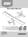
Turbo Timber SWS 2.0m
EFL71750 EFL71765
Instruction Manual
Bedienungsanleitung
Manuel d’utilisation
Manuale di Istruzioni
270976
Created 8/23
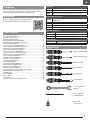
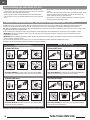
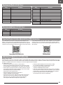
Scan the QR code and select the Manuals and Support quick links from the product page for
the most up-to-date manual information.
Scannen Sie den QR-Code und wählen Sie auf der Produktseite die Quicklinks Handbücher
und Unterstützung, um die aktuellsten informationen zu Handbücher.
Scannez le code QR et sélectionnez les liens rapides Manuals and Support sur la page du
produit pour obtenir les informations les plus récentes sur le manuel.
Scannerizzare il codice QR e selezionare i Link veloci Manuali e Supporto dalla pagina del
prodotto per le informazioni manuali più aggiornate.

EN
2Turbo Timber SWS 2.0m
Safety Precautions and Warnings
NOTICE
All instructions, warranties and other collateral documents are subject to change at the sole discretion of Horizon Hobby, LLC. For up-to-date product literature, visit
horizonhobby.com or towerhobbies.com and click on the support or resources tab for this product.
AGE RECOMMENDATION: Not for children under 14 years. This is not a toy.
MEANING OF SPECIAL LANGUAGE
The following terms are used throughout the product literature to indicate various levels of potential harm when operating this product:
WARNING: Procedures, which if not properly followed, create the probability of property damage, collateral damage, and serious injury OR create a high probability of
superficial injury.
CAUTION: Procedures, which if not properly followed, create the probability of physical property damage AND a possibility of serious injury.
NOTICE: Procedures, which if not properly followed, create a possibility of physical property damage AND little or no possibility of injury.
WARNING: Read the ENTIRE instruction manual to become familiar with the features of the product before operating. Failure to operate the product correctly can
result in damage to the product, personal property and cause serious injury.
This is a sophisticated hobby product. It must be operated with caution and common sense and requires some basic mechanical ability. Failure to operate this Product
in a safe and responsible manner could result in injury or damage to the product or other property. This product is not intended for use by children without direct adult
supervision. Do not use with incompatible components or alter this product in any way outside of the instructions provided by Horizon Hobby, LLC. This manual contains
instructions for safety, operation and maintenance. It is essential to read and follow all the instructions and warnings in the manual, prior to assembly, setup or use, in
order to operate correctly and avoid damage or serious injury.
As the user of this product, you are solely responsible for operating in a manner that does not endanger yourself and others or result in damage to the product or the
property of others.
• Always keep a safe distance in all directions around your model to avoid
collisions or injury. This model is controlled by a radio signal subject to
interference from many sources outside your control. Interference can cause
momentary loss of control.
• Always operate your model in open spaces away from full-size vehicles, traffic
and people.
• Always carefully follow the directions and warnings for this and any optional
support equipment (chargers, rechargeable battery packs, etc.).
• Always keep all chemicals, small parts and anything electrical out of the reach
of children.
• Always avoid water exposure to all equipment not specifically designed and
protected for this purpose. Moisture causes damage to electronics.
• Never place any portion of the model in your mouth as it could cause serious
injury or even death.
• Never operate your model with low transmitter batteries.
• Always keep aircraft in sight and under control.
• Always use fully charged batteries.
• Always keep transmitter powered on while aircraft is powered.
• Always remove batteries before disassembly.
• Always keep moving parts clean.
• Always keep parts dry.
• Always let parts cool after use before touching.
• Always remove batteries after use.
• Always ensure failsafe is properly set before flying.
• Never operate aircraft with damaged wiring.
• Never touch moving parts.
WARNING AGAINST COUNTERFEIT PRODUCTS: If you ever need to replace your Spektrum receiver found in a Horizon Hobby product, always purchase from
Horizon Hobby, LLC or a Horizon Hobby authorized dealer to ensure authentic high-quality Spektrum product. Horizon Hobby, LLC disclaims all support and
warranty with regards, but not limited to, compatibility and performance of counterfeit products or products claiming compatibility with DSM or Spektrum technology.

EN
3
Optional Batteries
SPMX76S30 7000mAh 6S 22.2V Smart G2 30C;
SPMX56S50 5000mAh 6S 22.2V Smart G2 50C;
• 5.5mm Nut Driver
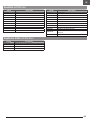
Safety Precautions and Warnings ...........................................................................2
Transmitter Setup BNF Basic ..................................................................................4
Model Assembly ARF/BNF Basic ............................................................................. 5
General Binding Tips and Failsafe BNF Basic ........................................................ 19
Transmitter and Receiver Binding / Enabling and
Disabling SAFE Select BNF Basic .........................................................................19
Control Surface Centering ARF/BNF Basic ............................................................20
Battery Installation and ESC Arming ARF/BNF Basic .............................................20
SAFE® Select Switch Designation BNF Basic.......................................................21
Smart™ Technology Telemetry BNF Basic ...........................................................21
Control Surface Direction ARF/BNF Basic .............................................................22
Propeller and Spinner Installation ARF/BNF Basic .................................................23
Dual Rates and Control Throws ARF/BNF Basic ....................................................24
Center of Gravity (CG) ARF/BNF Basic ................................................................... 24
Flying Tips and Repairs ARF/BNF Basic ................................................................25
SAFE Select Flying Tips BNF Basic .......................................................................25
In Flight Trimming ARF/BNF Basic ........................................................................26
Post Flight ARF/BNF Basic .................................................................................... 26
Troubleshooting Guide AS3X BNF Basic ................................................................27
Troubleshooting Guide ARF/BNF Basic ..................................................................27
Replacement Parts ARF/BNF Basic ....................................................................... 28
Recommended Items ARF/BNF Basic ...................................................................28
Important Federal Aviation Administration (FAA) Information ................................. 28
AMA National Model Aircraft Safety Code .............................................................28
Limited Warranty .................................................................................................29
Contact Information .............................................................................................29
FCC Information ................................................................................................... 30
IC Information ......................................................................................................30
Compliance Information for the European Union ...................................................30
Table of Contents
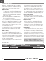
Registration
Introduction
Register your product today to join our mailing list and keep
up to date with product updates, offers and E-flite® news.
The E-flite® Turbo Timber® SWS (Sport Wood Series) 2.0m is a larger and sportier
version of the incredibly popular Turbo Timber 1.5m models that also features the
benefits of lightweight, rigid and strong built-up wood construction!
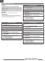
Required Tools
• Phillips Screwdriver (PH#0)
• Phillips Screwdriver (PH#1)
• Slotted Screwdriver
• 2.5mm Hex Driver
• 1.5mm Hex Driver
• 1/2-inch or Adjustable
Wrench x2
• 5/32” (2mm) drill bit
and drill (Optional)
• Thin CA glue
(Cyanoacrylate)
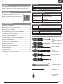
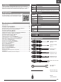
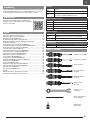
Included Equipment (BNF Basic)
Receiver Spektrum™ AR8630T 8CH SAFE® and AS3X® Telemetry Receiver
(SPMAR8360T)
ESC Avian 100 Amp Smart Brushless ESC, 3S-6S:IC5 (SPMXAE1100)
Motor Avian 5055-500Kv Outrunner Brushless Motor (SPMXAM4740)
Propeller 16 x 6E (EFLP71764)
Servos (6) A6380 H-T/H-S Digital HV Servo (SPMSA6380)
Recommended Equipment
Transmitter NX8 8Ch DSMX Transmitter Only (SPMR8200)
Flight Battery 5000mAh 6S 22.2V Smart G2 50C; IC3 (SPMX56S50)
Battery Charger S2100 G2 2x100W AC Smart Charge (SPMXC2000)
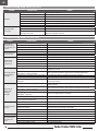
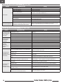
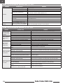
Specications
Wingspan 80.0in (2032mm)
Length 55.98in (1422mm)
Weight Without Battery: 122.3oz (3468g)
With Recommended 6S 5000mAh battery: 148.7oz (4216g)
11
2.5
1.5
6
5.5

EN
4Turbo Timber SWS 2.0m
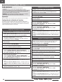
Dual Rates
Take rst ights in Low Rate. For landings, use high rate elevator.
NOTICE: To ensure AS3X® technology functions properly, do not lower rate
values below 50%. If lower rates are desired, manually adjust the position of the
pushrods on the servo arm.
NOTICE: If oscillation occurs at high speed, refer to the Troubleshooting Guide
for more information.
Exponential
After first flights, you may adjust exponential in your transmitter.
Telemetry Setup
See the Telemetry Setup table after binding. In order for the ESC and battery
information to auto-populate in your transmitter’s telemetry menu, you must begin
telemetry setup with the aircraft bound and connected.
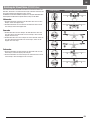
Transmitter Setup BNF Basic
DX Series Transmitter Setup
1. Power ON your transmitter, click on scroll wheel, roll to System Setup and
click the scroll wheel. Choose yes.
2. Go to Model Select and choose <Add New Model> at the bottom of the list.
The system asks if you want to create a new model, select Create
3. Set Model Type: Select Airplane Model Type by choosing the airplane.
The system asks you to confirm model type, data will be reset. Select YES
4. Set Model Name: Input a name for your model file
5. Select <Main Screen>, Click the scroll wheel to enter the Function List
6. Set D/R (Dual Rate) and Expo; Aileron
Set Switch: Switch F
Set High Rates: 100%, Expo 10% - Low Rates: 70%, Expo 5%
7. Set D/R (Dual Rate) and Expo; Elevator
Set Switch: SWITCH C
Set High Rates: 100%, Expo 10% - Low Rates 70%, Expo 5%
8. Set Flap System
Set Pos 0: Flap to 45%, Elevator to 0%
Set Pos 1: Flap to 0%, Elevator to 3%
Set Pos 2: Flap to -45%, Elevator to 9%
9. Set Throttle Cut; Switch: Switch H, Position: -100%
iX Series Transmitter Setup
1. Power ON your transmitter and begin once the Spektrtum Airware app is
open.
Select the orange pen icon in the upper left corner of the screen, the system
asks for permission to Turn Off RF, select PROCEED
2. Select the three dots in the upper right corner of the screen,
select Add a New Model
3. Select Model Option, choose DEFAULT, select Airplane.
The system asks if you want to create a new acro model, select Create
4. Select the last model on the list, named Acro.
Tap on the word Acro and rename the file to a name of your choice
5. Tap and hold the back arrow icon in the upper left corner of the screen to
return to the main screen
6. Go to the Model Adjust menu
7. Set Dual Rates and Expo; Select Aileron
Set Switch: Switch F
Set High Rates: 100%, Expo 10% - Low Rates: 70%, Expo 5%
8. Set Dual Rates and Expo; Select Elevator
Set Switch: SWITCH C
Set High Rates: 100%, Expo 10% - Low Rates 70%, Expo 5%
9. Set Flap System
Set Pos 0: Flap to 45%, Elevator to 0%
Set Pos 1: Flap to 0%, Elevator to 3%
Set Pos 2: Flap to -45%, Elevator to 9%
10. Set Throttle Cut; Switch: Switch H, Position: -100%
NX Series Transmitter Setup
1. Power ON your transmitter, click on scroll wheel, roll to System Setup and
click the scroll wheel. Choose yes.
2. Go to Model Select and choose <Add New Model> near the bottom of the
list. Select Airplane Model Type by choosing the airplane, select Create
3. Set Model Name: Input a name for your model file
4. Select <Main Screen>, Click the scroll wheel to enter the Function List
5. Set Rates and Expo; Aileron
Set Switch: Switch F
Set High Rates: 100%, Expo 10% - Low Rates: 70%, Expo 5%
6. Set Rates and Expo; Elevator
Set Switch: SWITCH C
Set High Rates: 100%, Expo 10% - Low Rates 70%, Expo 5%
Set Flap System
Set Pos 0: Flap to 45%, Elevator to 0%
Set Pos 1: Flap to 0%, Elevator to 3%
Set Pos 2: Flap to -45%, Elevator to 9%
7. Set Throttle Cut; Switch: Switch H, Position: -100%

EN
5
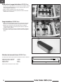
Servo Selection and Installation ARF
The recommended servos for this aircraft are the Spektrum A6380 Digital High-
Voltage Servo (SPMSA6380). Six servos are required for this model. If you choose
to install different servos, ensure they have the same or higher specifications for
torque and speed, at a similar weight.
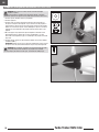
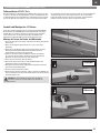
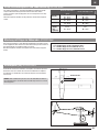
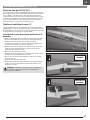
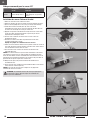
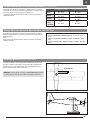
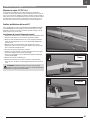
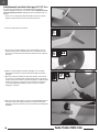
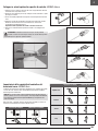
Rudder and Elevator Servo Installation
1. Locate the servo positions and mark the servo mounting holes.
2. Drill a 1/16” (1.5mm) pilot hole for each mounting screw.
3. Thread one of the self-tapping screws included with the servos to cut threads
into all the servo mounting screw holes with a Phillips screwdriver (PH#0),
remove the screw.
4. Apply one drop of thin CA glue to each screw hole. Allow the CA to cure, do not
use accelerator. Repeat this process for all servo mounting locations.
5. Guide the servo leads through the fuselage.
6. Install the servos as shown, with the output shaft oriented toward the front of
the model in all mounting locations.
7. Secure the servos in place with the included self-tapping screws using a
Phillips screwdriver (PH#0).
8. Center the servo using the radio system.
9. Place the servo arm on the servo so it is perpendicular to the servo centerline.
Install the servo arm retainer screws included with your servos.
CAUTION: Incorrect installation of the servos could cause a crash. Always
perform a control surface check after making any changes.
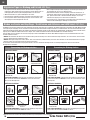
Model Assembly ARF/BNF Basic
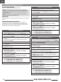
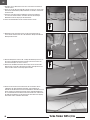
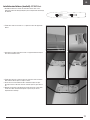
Removing Wrinkles ARF/BNF Basic
The covering of your model may develop wrinkles during shipping and require the
use of a heat gun and covering glove or covering iron with a sealing iron sock to
remove them. Use caution while working around areas where the colors overlap to
prevent separating the colors. Avoid using too much heat, which could separate the
colors. Placing a cool damp cloth on adjacent colors will also help in preventing the
separation of the colors while removing wrinkles.
M3x 8 M3x 10
M3x 25
M3
3mm
M2.6x 20
M2.6x 10
M2.6x 8
M6
6mm
M3x 8 M3x 10
M3x 25
M3
3mm
M2.6x 20
M2.6x 10
M2.6x 8
M6
6mm
Rudder
Elevator

EN
6Turbo Timber SWS 2.0m
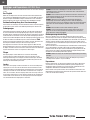
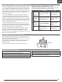
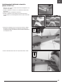
Recommended servo wiring ARF
Flap and Aileron Servo Installation
1. Remove the covers for the flap and aileron servos.
2. Locate the servo positions and mark the servo mounting holes.
3. Drill a 1/16” (1.5mm) pilot hole for each mounting screw.
4. Thread one of the self-tapping screws included with the servos to cut threads
into all the servo mounting screw holes with a Phillips screwdriver (PH#0),
remove the screw.
5. Apply one drop of thin CA glue to each screw hole. Allow the CA to cure, do not
use accelerator. Repeat this process for all servo mounting locations.
6. Secure the servos in place using the screws included with the servos and a
2.0mm hex wrench.
7. Select a servo arm with output hole spacing matching the chart under
Control Horn And Servo Arm Settings.
8. Center the servo, and install the servo arm in a centered position with the
servo arm 90° to the pushrod at neutral. Secure the servo arm using the screw
included with your servos.
9. Pull the servo leads through the wing where required with the string that comes
pre-installed in the wing.
TIP: If the string comes out and you need to re-route a lead through the wing, tie a
small nut or other small weight to the end of a string. Hold the wing vertically and
insert the weighted end of the string in the servo mounting hole. Feed the string
into the wing, and angle the wing to use gravity to pull the weighted line through
the wing.
10. Mark the leads so they can be easily identified when installing the wing.
11. Secure the servo cover with the included M2.6 x 8mm self-tapping screws
using a Phillips screwdriver (PH#0).
TIP: The slots in the servo covers will align with the flap and aileron control horns.
CAUTION: Incorrect installation of the servos could cause a crash. Always
perform a control surface check after making any changes.
From the receiver
to the wing
From the servo,
through the wing
Flaps and
Ailerons
Two Y-Harnesses or
Four 6 inch extensions
None required for flaps
Two 12 inch extensions for ailerons
M3x 8 M3x 10
M3x 25
M3
3mm
M2.6x 20
M2.6x 10
M2.6x 8
M6
6mm

EN
7
M3x 8 M3x 10
M3x 25
M3
3mm
M2.6x 20
M2.6x 10
M2.6x 8
M6
6mm
M3x 8 M3x 10
M3x 25
M3
3mm
M2.6x 20
M2.6x 10
M2.6x 8
M6
6mm
M3x 8 M3x 10
M3x 25
M3
3mm
M2.6x 20
M2.6x 10
M2.6x 8
M6
6mm
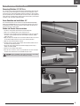
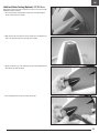
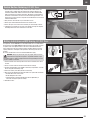
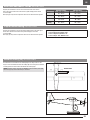
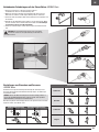
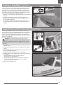
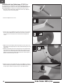
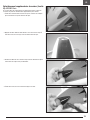
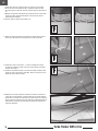
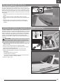
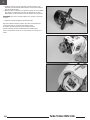
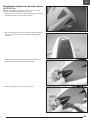
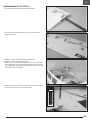
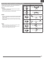
Horizontal and Vertical Stabilizer Installation ARF/BNF Basic
1. Remove the screw holding the filler in position using a
Phillips screwdriver (PH#2).
2. Install the horizontal stabilizer, with the control horn facing down.
3. Replace the filler piece in the fuselage.
4. Install the vertical stabilizer from the top of the fuselage, leaving the M3
mounting studs protruding through the bottom of the fuselage.
5. Place a 3mm washer on each stud, and secure in place with M3 nylon lock
nuts using a 5.5mm nut driver. Do not overtighten these nuts and compress the
wood. Check periodically to make sure they remain tight.
6. Secure the tail wheel bracket using three M2.5 x 10mm sheet metal screws.

EN
8Turbo Timber SWS 2.0m
M3x 8 M3x 10
M3x 25
M3
3mm
M2.6x 20
M2.6x 10
M2.6x 8
M6
6mm
M3x 8 M3x 10
M3x 25
M3
3mm
M2.6x 20
M2.6x 10
M2.6x 8
M6
6mm
M3x 8 M3x 10
M3x 25
M3
3mm
M2.6x 20
M2.6x 10
M2.6x 8
M6
6mm
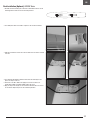
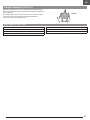
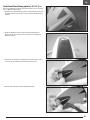
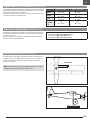
Landing Gear Installation ARF/BNF Basic
An optional float set is available for your aircraft. When installing the floats,
continue to following section, Connect the Pushrods to the Control Surfaces. The
floats will be installed later in the manual.
1. Secure the axle to the landing gear using two 1/2-inch wrenches. Align the flat
area on the axle toward the bottom of the aircraft.
2. Slide a wheel collar onto the axle.
3. Slide the wheel on the axle. Apply a drop of threadlock on a 3mm setscrew.
Secure the wheel collar using the 3mm setscrew. Tighten the setscrew onto the
flat area of the axle using a 1.5mm hex wrench.
4. Align the landing gear mounting holes with the holes on the bottom of the
fuselage. Fit the landing gear cover over the landing gear.
5. Apply a drop of threadlock on each of the three M3 x 12mm machine screws.
Place a washer, then lock washer, on each screw. The screws go through the
cover, through the landing gear, and into the blind nuts in the fuselage. Be
careful not to cross thread the screws. Use a large Phillips screw driver (PH#2)
to secure the landing gear and cover in place.
6. Apply a thin layer of contact adhesive, such as E6000, to the outside of the
landing gear. Position the landing gear fairing and use a clamp to hold the
fairing in position until the adhesive cures.

EN
9
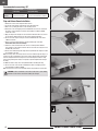
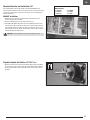
Motor and ESC Installation ARF
1. Mount the speed control inside the fuselage using a hook and loop strap.
2. Route the leads to the motor through the opening in the firewall.
3. Place a drop of threadlock on each of the M4 x 15 machine screws. Use a large
Phillips screw driver (PH#2) to tighten the screws.
4. Secure the motor box to the firewall using four M4 x 15 machine screws, four
M4 washers and four M4 lock washers. Use a large Phillips screw driver (PH#2)
to tighten the screws.
M3x 8 M3x 10
M3x 25
M3
3mm
M2.6x 20
M2.6x 10
M2.6x 8
M6
6mm
M3x 8 M3x 10
M3x 25
M3
3mm
M2.6x 20
M2.6x 10
M2.6x 8
M6
6mm
M3x 8 M3x 10
M3x 25
M3
3mm
M2.6x 20
M2.6x 10
M2.6x 8
M6
6mm

EN
10 Turbo Timber SWS 2.0m
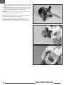
5. Install the X mount to the back of the motor with four M3 x 3mm screws using
a Phillips screwdriver (PH#1). Place a drop of threadlock on each screw before
installation.
6. Mount the motor and X-mount to the firewall with four M3 x 10mm pan head
machine screws with 3mm lock washers using a Phillips screwdriver (PH#1),
with the motor wires extending through the hole in the firewall.
IMPORTANT: If the screws do not thread easily, do not use excessive pressure.
7. Connect the leads from the speed control to the motor.
After installing your electronics, verify the motor is rotating the correct direction. It
should rotate clockwise (viewed in the direction of flight).
If you need to reverse the motor direction, disconnect the battery first.
Reverse the motor direction by swapping any two of the three motor wires.
Secure the motor wires so they are out of the way, and not rubbing on the motor.

EN
11
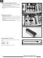
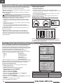
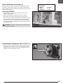
Receiver Selection and Installation ARF AR8630T Port Assignments
BND/PRG/SRXL2
1 = Throttle
2 = Ailerons
3 = Elevator
4 = Rudder
5 = Lights
6 = Flaps
The recommended receiver for this aircraft is the Spektrum AR8630T. If you
choose to install a different receiver, ensure that it is at least a 6-channel full range
receiver. Refer to the manual of your chosen receiver for correct installation and
operation instructions.
AR8630T Installation
1. Connect the servos, extensions and ESC to their respective ports on the
receiver using the table at the right.
2. Connect the lighting harness to the unused channel 5 port.
3. Using high quality double-sided servo tape (not included) mount the receiver
to the flat area inside the fuselage as shown. The receiver should be mounted
in the orientation shown, parallel to the length of the fuselage, with the servo
ports facing the front of the aircraft. The orientation of the receiver is critical for
all AS3X and SAFE technology setups.
CAUTION: Incorrect installation of the receiver could cause a crash.
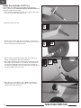
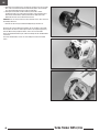
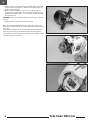
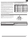
Propeller Adapter Installation ARF/BNF Basic
1. Remove the washer and nut from the prop adapter. Apply a drop of threadlock
on each of the four M3 x 8 socket head cap screws. Mount the prop adapter to
the motor with four M3 x 8mm socket head machine screws using a 2.5mm
hex driver.

EN
12 Turbo Timber SWS 2.0m
X
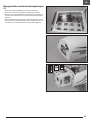
Battery Strap ARF/BNF Basic
1. Connect a piece of hook material to the loop material at one end with a 2 inch
(50mm) overlap to create a strap.
2. Apply CA to the back of the hook and loop material where it overlaps. This will
adhere to the bottom of the battery tray and prevent the battery strap from
being pulled out.
3. Slide the strap through a slot (avoiding any wiring inside the fuselage), and feed
it through the slot on the other side of the battery tray.
Battery Tray Hook and Loop ARF/BNF Basic
1. Adhesive backed hook and loop material will not stick to bare wood. Apply a
few drops of thin CA (or epoxy) to the battery tray area where you want the
hook and loop material to be applied.
2. Remove the backing material and apply the hook side to the tray.
3. Apply the opposite side to the battery. (Avoid covering any warning labels on
the battery.)
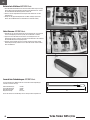
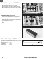
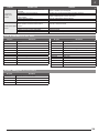
Pushrods Selection ARF/BNF Basic
Four different lengths of pushrods are included with this model. They are as
follows:
Elevator Linkage: 137mm
Rudder Linkage: 159mm
Aileron Linkage: 76mm
Flap Linkage: 63.5mm
Make sure to use the linkages in the correct locations.

EN
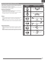
13
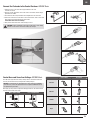
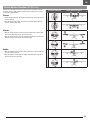
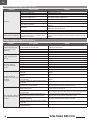
More control throw Less control throw
Elevator
Flaps
Tail wheel
Control Horns Servo Arms
Elevator
Ailerons
Rudder
Flaps
1.
2.
3.
4.
The table to the right shows the factory settings for the control horns and servo
arms. Fly the aircraft at factory settings before making changes.
NOTICE: If control throws are changed from the factory settings, the AR8630T
gain values may need to be adjusted. Refer to the Spektrum AR8630T manual
for adjustment of gain values.
After flying, you may choose to adjust the linkage positions for the desired control
response. See the table to the right.
Connect the Pushrods to the Control Surfaces ARF/BNF Basic
1. Center the servo, so the servo arm is perpendicular to the servo
centerline at neutral.
2. Select the shorter pushrod to connect the servo to the elevator, and the longer
pushrod for the rudder..
3. Insert the bent end of the pushrod into the enlarged hole in the servo arm.
4. Connect the clevis to the control horn on the control surface. Select a servo arm
with output hole spacing matching the chart under
Control Horn And Servo Arm Settings.
5. Verify control surface directions and centering is correct.
CAUTION: Incorrect installation of the servos could cause a crash. Always
perform a control surface check after making any changes.
Control Horn and Servo Arm Settings ARF/BNF Basic

EN
14 Turbo Timber SWS 2.0m
M3x 8 M3x 10
M3x 25
M3
3mm
M2.6x 20
M2.6x 10
M2.6x 8
M6
6mm
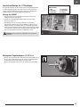
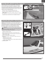
Cowling Installation ARF/BNF Basic
1. Guide the wiring for the lighting in the cowling through the hole in the firewall.
2. Slide the cowl into position, aligning the holes in the cowling with the holes in
the fuselage.
3. Secure the cowling using four M2.5 x 8mm sheet metal screws and a Phillips
screwdriver (PH#1).
4. Connect the lighting lead to the harness inside the fuselage.

EN
15
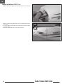
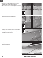
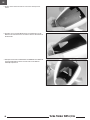
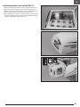
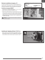
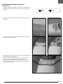
Additional Motor Cooling (Optional) ARF/BNF Basic
When flying in higher temperature environments, it may be necessary to provide
additional cooling for the motor.
1. Use a rotary tool with a sanding drum to remove the area indicated by the
decals on the bottom of the cowling.
2. Apply low-tack tape to the black area of the cowling. Use a felt-tipped pen to
make a line 25mm back from the front edge of the cowling.
3. Position the intake on top of the cowling. Center the intake and align the front
edge with the line made previously.
4. Use a felt-tipped pen to transfer the outline onto the tape.

EN
16 Turbo Timber SWS 2.0m
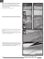
6. Use a rotary tool and sanding drum to remove the material on the inside line.
Remove the tape from the cowling.
7. Secure the intake using contact adhesive such as E6000. Use low-tack tape to
hold the intake in position until the adhesive fully cures.
5. Draw the outline of the intake 3mm the previous lines.

EN
17
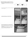
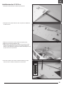
Float Installation (Optional) ARF/BNF Basic
1. Assemble the floats following the instructions included with the floats. Use the
mounting positions shown for the strut mounting locations.
2. Use a hobby knife with a #11 blade to expose the slots for the float mounts.
3. Slide the forward mount into the slot. The front float mount can then be inserted
in the slot.
4. Use a drill and 2mm drill bit to drill holes 4mm from the inside edges of the
gear for the straps at the rear.
5. Thread one of the M3 x 10mm self-tapping screws into each hole to cut
threads with a Phillips screwdriver (PH#0), remove the screw.
6. Apply one drop of thin CA glue to each screw hole. Allow the CA to cure, do not
use accelerator. Repeat this process for all mounting locations.

EN
18 Turbo Timber SWS 2.0m
M3x 8 M3x 10
M3x 25
M3
3mm
M2.6x 20
M2.6x 10
M2.6x 8
M6
6mm
M3x 8 M3x 10
M3x 25
M3
3mm
M2.6x 20
M2.6x 10
M2.6x 8
M6
6mm
M3x 8 M3x 10
M3x 25
M3
3mm
M2.6x 20
M2.6x 10
M2.6x 8
M6
6mm
7. Use a drill and 2mm drill bit to drill the remaining holes.
8. Thread one of the M3 x 10mm self-tapping screws into each hole to cut
threads with a Phillips screwdriver (PH#0), remove the screw.
9. Apply one drop of thin CA glue to each screw hole. Allow the CA to cure, do not
use accelerator. Repeat this process for all mounting locations.
10. Secure the straps using M3 x 10 sheet metal screws.
11. Repeat the previous steps to secure the rear mounts. Make sure to drill into the
hardwood located in the fuselage near the mounting slot.
14. Unplug the rudder servo, and connect the Y-harness included with the float set
to the receiver. Connect the rudder servo to the Y-harness. Cut a small slot in
the fuselage and secure the remaining lead where it can connect to the lead
from the float. Connect the lead from the float and check the operation of the
aircraft rudder and float rudder.
12. Use a hobby knife and #11 blade to remove the covering exposing the holes
for the angle support struts. (The holes can be seen easier from inside the
fuselage.)
13. Install the angle support struts, securing them to the fuselage with the two
nylon loop straps and four M3 x 10mm sheet metal screws. The holes for the
screws will need to be drilled in the fuselage.

EN
19
M3x 8 M3x 10
M3x 25
M3
3mm
M2.6x 20
M2.6x 10
M2.6x 8
M6
6mm
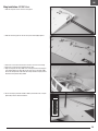
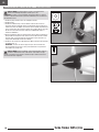
Wing Installation ARF/BNF Basic
1. Slide the wing tube into the socket in a wing panel.
6. Secure the wing in place with the M6 x 30mm nylon thumb screw, it may be
tightened by hand or slotted screw driver.
2. Slide the other wing panel on the tube. The panels will fit tightly together.
3. Connect the servo connectors from the receiver to the servos in the wings.
4. Connect the connectors for the lighting from the wing.
5. Align the wing with the wing saddle on the fuselage and insert the wing pins
in the leading edge of the wing with the hole at the front of the wing saddle.
Ensure the wiring remains fully inside the fuselage and does not get pinched
between the wing and the wing saddle.

EN
20 Turbo Timber SWS 2.0m
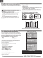
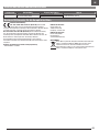
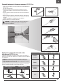
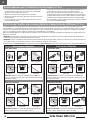
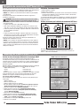
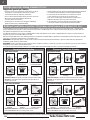
SAFE Select can also be activated via Forward Programming in compatible transmitters.
To Enable SAFE Select To Enable SAFE Select
To Disable SAFE Select To Disable SAFE Select
Using The Bind Button... Using The Bind Plug...
SAFE SELECT ENABLED: The control surfaces cycle back and forth twice
with a slight pause at neutral position every time the receiver is powered on.
SAFE SELECT DISABLED: The control surfaces cycle back and forth once
every time the receiver is powered on.
SAFE SELECT DISABLED: The control surfaces cycle back and forth once
every time the receiver is powered on.
SAFE SELECT ENABLED:
The control surfaces cycle back and forth twice with a
slight pause at neutral position every time the receiver is powered on.
Press and hold Bind Button
Press and hold Bind Button
Release Bind ButtonOrange Flashing LED
Connect PowerLower Throttle
Bind TX to RX
Bind TX to RX
Lower Throttle Connect Power
Release Bind Button
Orange Flashing LED
Install Bind Plug
Remove Bind Plug
Connect Power
Bind TX to RX
Lower Throttle
Install Bind Plug
Remove Bind Plug
Lower Throttle Connect Power
Bind TX to RXOrange Flashing LED
Orange Flashing LED
BIND
BIND
BIND
BIND
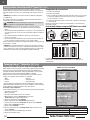
General Binding Tips and Failsafe BNF Basic
Transmitter and Receiver Binding / Enabling and Disabling SAFE Select BNF Basic
The BNF Basic version of this airplane includes SAFE Select technology, enabling you to choose the level of flight protection. SAFE mode includes angle limits and
automatic self leveling. AS3X mode provides the pilot with a direct response to the control sticks. SAFE Select is enabled or disabled during the bind process.
With SAFE Select disabled the aircraft is always in AS3X mode. With SAFE Select enabled the aircraft will be in SAFE Select mode all the time, or you can assign a switch
to toggle between SAFE Select and AS3X modes.
Thanks to SAFE Select technology, this aircraft can be configured for full-time SAFE mode, full-time AS3X mode, or mode selection can be assigned to a switch.
IMPORTANT: Before binding, read the transmitter setup section in this manual and complete the transmitter setup table to ensure your transmitter is properly
programmed for this aircraft.
IMPORTANT: Move the transmitter flight controls (rudder, elevators, and ailerons) and the throttle trim to neutral. Move the throttle to low before and during binding.
This process defines the failsafe settings.
You can use either the bind button on the receiver case or the conventional bind plug to complete the binding and SAFE Select process.
SAFE Select can also be activated via Forward Programming in compatible transmitters.
• The included receiver has been specifically programmed for operation of this
aircraft. Refer to the receiver manual for correct setup if the receiver is replaced.
• Keep away from large metal objects while binding.
• Do not point the transmitter’s antenna directly at the receiver while binding.
• The orange LED on the receiver will flash rapidly when the receiver enters bind
mode.
• Once bound, the receiver will retain its bind settings for that transmitter until you
re-bind.
• If the receiver loses transmitter communication, the failsafe will activate. Failsafe
moves the throttle channel to low throttle. Pitch and roll channels move to
actively stabilize the aircraft in a descending turn.
• If problems occur, refer to the troubleshooting guide or if needed, contact the
appropriate Horizon Product Support office.
Seite wird geladen ...
Seite wird geladen ...
Seite wird geladen ...
Seite wird geladen ...
Seite wird geladen ...
Seite wird geladen ...
Seite wird geladen ...
Seite wird geladen ...
Seite wird geladen ...
Seite wird geladen ...
Seite wird geladen ...
Seite wird geladen ...
Seite wird geladen ...
Seite wird geladen ...
Seite wird geladen ...
Seite wird geladen ...
Seite wird geladen ...
Seite wird geladen ...
Seite wird geladen ...
Seite wird geladen ...
Seite wird geladen ...
Seite wird geladen ...
Seite wird geladen ...
Seite wird geladen ...
Seite wird geladen ...
Seite wird geladen ...
Seite wird geladen ...
Seite wird geladen ...
Seite wird geladen ...
Seite wird geladen ...
Seite wird geladen ...
Seite wird geladen ...
Seite wird geladen ...
Seite wird geladen ...
Seite wird geladen ...
Seite wird geladen ...
Seite wird geladen ...
Seite wird geladen ...
Seite wird geladen ...
Seite wird geladen ...
Seite wird geladen ...
Seite wird geladen ...
Seite wird geladen ...
Seite wird geladen ...
Seite wird geladen ...
Seite wird geladen ...
Seite wird geladen ...
Seite wird geladen ...
Seite wird geladen ...
Seite wird geladen ...
Seite wird geladen ...
Seite wird geladen ...
Seite wird geladen ...
Seite wird geladen ...
Seite wird geladen ...
Seite wird geladen ...
Seite wird geladen ...
Seite wird geladen ...
Seite wird geladen ...
Seite wird geladen ...
Seite wird geladen ...
Seite wird geladen ...
Seite wird geladen ...
Seite wird geladen ...
Seite wird geladen ...
Seite wird geladen ...
Seite wird geladen ...
Seite wird geladen ...
Seite wird geladen ...
Seite wird geladen ...
Seite wird geladen ...
Seite wird geladen ...
Seite wird geladen ...
Seite wird geladen ...
Seite wird geladen ...
Seite wird geladen ...
Seite wird geladen ...
Seite wird geladen ...
Seite wird geladen ...
Seite wird geladen ...
Seite wird geladen ...
Seite wird geladen ...
Seite wird geladen ...
Seite wird geladen ...
Seite wird geladen ...
Seite wird geladen ...
Seite wird geladen ...
Seite wird geladen ...
Seite wird geladen ...
Seite wird geladen ...
Seite wird geladen ...
Seite wird geladen ...
Seite wird geladen ...
Seite wird geladen ...
Seite wird geladen ...
Seite wird geladen ...
Seite wird geladen ...
Seite wird geladen ...
Seite wird geladen ...
Seite wird geladen ...
Seite wird geladen ...
Seite wird geladen ...
Seite wird geladen ...
Seite wird geladen ...
-
 1
1
-
 2
2
-
 3
3
-
 4
4
-
 5
5
-
 6
6
-
 7
7
-
 8
8
-
 9
9
-
 10
10
-
 11
11
-
 12
12
-
 13
13
-
 14
14
-
 15
15
-
 16
16
-
 17
17
-
 18
18
-
 19
19
-
 20
20
-
 21
21
-
 22
22
-
 23
23
-
 24
24
-
 25
25
-
 26
26
-
 27
27
-
 28
28
-
 29
29
-
 30
30
-
 31
31
-
 32
32
-
 33
33
-
 34
34
-
 35
35
-
 36
36
-
 37
37
-
 38
38
-
 39
39
-
 40
40
-
 41
41
-
 42
42
-
 43
43
-
 44
44
-
 45
45
-
 46
46
-
 47
47
-
 48
48
-
 49
49
-
 50
50
-
 51
51
-
 52
52
-
 53
53
-
 54
54
-
 55
55
-
 56
56
-
 57
57
-
 58
58
-
 59
59
-
 60
60
-
 61
61
-
 62
62
-
 63
63
-
 64
64
-
 65
65
-
 66
66
-
 67
67
-
 68
68
-
 69
69
-
 70
70
-
 71
71
-
 72
72
-
 73
73
-
 74
74
-
 75
75
-
 76
76
-
 77
77
-
 78
78
-
 79
79
-
 80
80
-
 81
81
-
 82
82
-
 83
83
-
 84
84
-
 85
85
-
 86
86
-
 87
87
-
 88
88
-
 89
89
-
 90
90
-
 91
91
-
 92
92
-
 93
93
-
 94
94
-
 95
95
-
 96
96
-
 97
97
-
 98
98
-
 99
99
-
 100
100
-
 101
101
-
 102
102
-
 103
103
-
 104
104
-
 105
105
-
 106
106
-
 107
107
-
 108
108
-
 109
109
-
 110
110
-
 111
111
-
 112
112
-
 113
113
-
 114
114
-
 115
115
-
 116
116
-
 117
117
-
 118
118
-
 119
119
-
 120
120
-
 121
121
-
 122
122
-
 123
123
-
 124
124


E-flite EFL71750 Bedienungsanleitung
- Kategorie
- Ferngesteuertes Spielzeug
- Typ
- Bedienungsanleitung
- Dieses Handbuch eignet sich auch für
in anderen Sprachen
- English: E-flite EFL71750 Owner's manual
- français: E-flite EFL71750 Le manuel du propriétaire
- italiano: E-flite EFL71750 Manuale del proprietario
