Horizon Hobby UMX YAK 54 3D Benutzerhandbuch
- Kategorie
- Ferngesteuertes Spielzeug
- Typ
- Benutzerhandbuch

Instruction Manual
Bedienungsanleitung
Manuel d’utilisation
Manuale di Istruzioni

2
EN
WARNING: Read the ENTIRE instruction manual to become familiar with the features of the
product before operating. Failure to operate the product correctly can result in damage to the product,
personal property and cause serious injury.
This is a sophisticated hobby product. It must be operated with caution and common sense and requires
some basic mechanical ability. Failure to operate this product in a safe and responsible manner could
result in injury or damage to the product or other property. This product is not intended for use by
children without direct adult supervision. Do not use with incompatible components or alter this product
in any way outside of the instructions provided by Horizon Hobby, LLC. This manual contains instructions
for safety, operation and maintenance. It is essential to read and follow all the instructions and warnings
in the manual, prior to assembly, setup or use, in order to operate correctly and avoid damage or serious
injury.
Age Recommendation: Not for children under 14
years. This is not a toy.
Safety Precautions and Warnings
• Always keep a safe distance in all directions
around your model to avoid collisions or injury.
This model is controlled by a radio signal subject
to interference from many sources outside your
control. Interference can cause momentary loss
of control.
• Always operate your model in open spaces away
from full-size vehicles, traffi c and people.
• Always carefully follow the directions and
warnings for this and any optional support equip-
ment (chargers, rechargeable battery packs,
etc.).
• Always keep all chemicals, small parts and
anything electrical out of the reach of children.
• Always avoid water exposure to all equipment
not specifi cally designed and protected for this
purpose. Moisture causes damage to electronics.
• Never place any portion of the model in your
mouth as it could cause serious injury or even
death.
• Never operate your model with low transmitter
batteries.
• Always keep aircraft in sight and under control.
• Always use fully charged batteries.
• Always keep the transmitter powered on while
aircraft is powered.
• Always remove batteries before disassembly.
• Always keep moving parts clean.
• Always keep parts dry.
• Always let parts cool after use before touching.
• Always remove batteries after use.
• Always ensure failsafe is properly set before
fl ying.
• Never operate aircraft with damaged wiring.
• Never touch moving parts.
Meaning of Special Language:
The following terms are used throughout the product literature to indicate various levels of potential
harm when operating this product:
NOTICE: Procedures, which if not properly followed, create a possibility of physical property damage
AND little or no possibility of injury.
CAUTION: Procedures, which if not properly followed, create the probability of physical property
damage AND a possibility of serious injury.
WARNING: Procedures, which if not properly followed, create the probability of property damage,
collateral damage, and serious injury OR create a high probability of superfi cial injury.
NOTICE
All instructions, warranties and other collateral documents are subject to change at the sole discretion
of Horizon Hobby, LLC. For up-to-date product literature, visit www.horizonhobby.com and click on the
support tab for this product.

3
EN
To register your product online, go to www.e-fl iterc.com
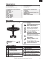
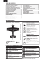
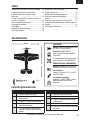
19.6 in (497mm)
16.9 in (430mm)
1.3oz
(36 g)
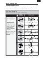
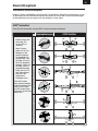
Table of Contents
Specifi cations
Wing Area: 37.2 sq. in.
(472.3 cm
2
)
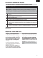
1. Charge flight battery.
2. Install flight battery in aircraft (once it
has been fully charged).
3. Bind aircraft to transmitter.
4. Make sure linkages move freely.
5. Perform Control Direction Test with
transmitter.
6. Set dual rates.
7. Adjust center of gravity.
8. Perform a radio system Range Check.
9. Find a safe and open area.
10. Plan flight for flying field conditions.
Prefl ight Checklist
Installed
Motor: Ultra Micro Brushed Motor
8.5mm x 23mm (EFLU5152)
Receiver : DSM2/DSMX UM AS3X
®
Receiver/Servos/ESC (EFLU5164)
(2) 2.3-Gram Performance Linear Long
Throw Servo (SPMSA2030L)
Required to Complete
Battery: 150mAh 1S 3.7V 25C/45C
Li-Po, (EFLB1501S25 or EFLB1501S45)
Battery Charger:
Celectra™ 4-Port 1S 3.7V 0.3A DC
Li-Po Charger (EFLC1004)
Recommended Transmitter:
Full range Spektrum™ DSM2
®
/DSMX
®
with dual-rates (DX4e and up)
Transmitter and Receiver Binding ..........................4
Low Voltage Cutoff (LVC) .......................................4
Alternate Flight Mode Programming ......................5
ESC/Receiver Arming, Battery Installation and
Center of Gravity ...................................................6
Control Direction Tests ..........................................7
Control Centering .................................................8
Trimming ..............................................................8
Control Horn Settings ............................................8
Dual Rates and Expos ...........................................8
Flying Tips and Repairs .........................................9
Post Flight Checklist .............................................9
Power Components Service ................................10
Troubleshooting Guide ........................................11
Limited Warranty ................................................12
Warranty and Service Contact Information ..........14
IC Information .....................................................14
FCC Information ..................................................14
Compliance Information for the European Union ..15
Replacement Parts ...............................................54
Optional Parts and Accessories ............................55

4
EN
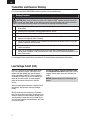
For a list of compatible DSM2/DSMX transmitters, please visit www.bindnfl y.com
Transmitter and Receiver Binding
For subsequent fl ights, power ON the transmitter for 5 seconds before connecting the fl ight battery.
Binding Procedure
CAUTION: When using a Futaba transmitter with a Spektrum DSM
®
module, you must reverse the
throttle channel and rebind. Refer to your Spektrum module manual for binding and failsafe instructions.
Refer to your Futaba transmitter manual for instructions on reversing the throttle channel.
1. Refer to your transmitter’s unique instructions for binding to a receiver (location of transmitter’s
Bind control).
2. Make sure the flight battery is disconnected from the aircraft.
3. Ensure the transmitter is powered OFF.
4. Connect the flight battery to the aircraft and turn the aircraft upright. The receiver LED will
begin to flash (typically after 5 seconds).
5. Ensure that control surface trims are centered and the throttle and throttle trims are in the low
position to correctly set the failsafe.
6. Put your transmitter into bind mode. Refer to your transmitter’s manual for binding button or
switch instructions.
7. After 5 to 10 seconds, the receiver status LED will turn solid, indicating that the receiver is
bound to the transmitter. If the LED does not turn solid, refer to the Troubleshooting Guide at the
back of the manual.
When a Li-Po battery is discharged below 3V per
cell, it will not hold a charge. The aircraft’s ESC
protects the fl ight battery from over-discharge
using Low Voltage Cutoff (LVC). Once the battery
discharges to 3V per cell, the LVC will reduce the
power to the motor in order to leave adequate
power to the receiver and servos to land the
aircraft.
When the motor power decreases, land the aircraft
immediately and replace or recharge the fl ight
battery.
Always disconnect and remove the Li-Po battery
from the aircraft after each fl ight. Charge your Li-Po
battery to about half capacity before storage. Make
sure the battery charge does not fall below 3V per
cell. Failure to unplug a connected battery will result
in trickle discharge.
For your fi rst fl ights, set your transmitter timer
or a stopwatch to 4 minutes. Adjust your timer for
longer or shorter fl ights once you have fl own the
model.
NOTICE: Repeated fl ying to LVC will damage the
battery.
Low Voltage Cutoff (LVC)

5
EN
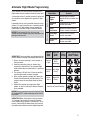
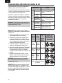
Alternate Flight Mode Programming
Default
Flight
Mode
Alternate
Flight
Mode
Ch 5
Switch
Position
Mode Programming
Stick Positions
(Mode 2 shown)
General
Flight
Standard
AS3X
®
Technology
0
Standard
AS3X
®
Knife Edge
Assist
1
Hover
Assist
Torque Roll
Assist
2
Reset all to Default Settings
Out of the box, the aircraft comes standard with 3
fl ight modes, shown in bold in the chart to the right.
A transmitter with a 2-position channel 5 switch will
only allow the use of position 0 or position 2 fl ight
modes.
If possible (refer to your transmitter manual) assign
channel 5 in your transmitter to a 3-position switch
to operate all 3 fl ight modes. You can modify the
fl ight modes available using the directions below.
NOTICE: Fast forward flight in the Hover and
Torque Roll Assist modes may cause oscillation and
damage to the aircraft.
IMPORTANT: Your transmitter must be bound to the
receiver before changing fl ight mode programming.
1. Ensure all servo reversing is set to normal in
the transmitter.
2. Hold the transmitter sticks as shown, then
connect the flight battery. The assigned flight
mode switch does not need to be in a particular
position.
3. The receiver LED will flash 3 times to confirm
that the flight mode has been changed.
4. After a switch position change, fully lower the
throttle, then disconnect the flight battery. The
receiver stores the new flight mode for future
flights.
5. Repeat this process to change other flight
modes, or reset all settings to default using the
chart provided.
NOTICE: Always launch the aircraft in General Flight
or Standard AS3X
®
mode or damage to the aircraft
may result.
IMPORTANT: When the throttle is fully lowered for
1–2 seconds, the aircraft will reset to Standard
AS3X mode until the throttle is raised again. This is
normal. Standard AS3X mode allows you to launch
the model again without a control input being held.
Flight Mode Benefi ts
Default
General
Flight
Heading hold on ailerons,
standard AS3X on elevator and
rudder.
Standard
AS3X
Standard AS3X on ailerons,
elevator and rudder.
Hover
Assistance
Aggressive heading hold on
ailerons, elevator and rudder.
Alternate
Knife Edge
Assist
Heading hold on ailerons,
elevator and rudder.
Torque Roll
Assist
Standard AS3X on ailerons,
aggressive heading hold on
elevator and rudder.

6
EN
1-2-3-4-5 Sec.
3
4
1
2
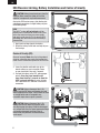
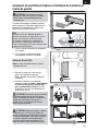
ESC/Receiver Arming, Battery Installation and Center of Gravity
CAUTION: Always keep hands away from the
propeller. When armed, the motor will turn the
propeller in response to any throttle movement.
Arming the ESC/receiver occurs after binding, but
subsequent connection of a fl ight battery requires
the following steps.
AS3X
The AS3X
®
system will not activate until the
throttle stick is increased for the fi rst time. Once
active, the control surfaces may move rapidly
and noisily on the aircraft. This is normal. AS3X
technology will remain active until the battery is
disconnected.
1. Apply hook and loop tape to the battery.
2. Attach the battery to the hook and loop strip on
the fuselage.
Center of Gravity (CG)
Measure foreward 94mm from the trailing edge of
the wing, where the wing meets the fuselage and
place a mark. Balance the airplane on this CG mark.
3. Lower the throttle and throttle trim to the
lowest settings on your transmitter. Power
on your transmitter, then wait 5 seconds.
4. Connect the battery to the ESC, noting proper
polarity. Keep the plane immobile and
away from wind for 5 seconds to allow the
AS3X system to initialize. A series of tones
and a continuous LED indicates a successful
connection.
CAUTION: Always disconnect the Li-Po
battery from the ESC when not fl ying to eliminate
power supplied to the motor. The ESC does not have
an arming switch and will respond to any
transmitter input when a signal is present.
CAUTION: Always disconnect the Li-Po
battery from the ESC when not fl ying to avoid
over-discharging the battery. Batteries discharged
to a voltage lower than the lowest approved voltage
may become damaged, resulting in loss of
performance and potential fi re when batteries
are charged.
94mm

7
EN
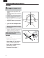
Aircraft
movement
AS3X Reaction
1. Advance the throttle above
25% to activate the AS3X
system.
2. Fully lower the throttle.
3. Move the entire aircraft
as shown and ensure the
control surfaces move in
the direction indicated in
the graphic. If the control
surfaces do not respond
as shown, do not fly
the aircraft. Refer to the
receiver manual for more
information.
Once the AS3X system is active,
control surfaces may move
rapidly. This is normal. AS3X
is active until the battery is
disconnected.
ElevatorAileronRudder
AS3X
®
Control Direction Test
This test ensures that the AS3X
®
control system is functioning properly.
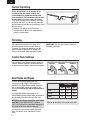
Control Direction Tests
Traditional Control Direction Test
You should bind your aircraft and transmitter before doing these tests. Move the controls on the transmitter
to make sure the aircraft control surfaces move correctly and in the proper direction. Make sure the tail
linkages move freely and that paint or decals are not adhered to them.

8
EN
Dual Rates and Expos
To obtain the best fl ight performance, we
recommend using a DSM2/DSMX transmitter
capable of Dual Rates. Before binding, ensure that
you are starting with a blank acro model in your
transmitter. Set wing type and servo reversing to
normal.
The suggested settings shown here are the
recommended starting settings. Adjust according to
the individual preferences after the initial fl ight.
NOTICE: Do not set your transmitter travel adjust
over 100%. If the TRAVEL ADJUST is set over
100%, it will not result in more control movement, it
will overdrive the servo and cause damage.
It is normal for linear servos to make signifi cant
noise. The noise is not an indication of a faulty
servo.
Tip: For the fi rst fl ight, fl y the model in low rate.
Dual Rates
Low High 3D
Aileron 50% 70% 100%
Elevator 40% 70% 100%
Rudder 50% 70% 100%
Before the fi rst fl ights, or in the event of an
accident, make sure control surfaces are
centered when the transmitter controls and
trims are neutral. The transmitter sub-trim must
be set to zero. Adjust the linkages mechanically
if the control surfaces are not centered. Use of the
transmitter sub-trims may not correctly center the
aircraft control surfaces due to the mechanical limits
of linear servos.
• Make the U-shape narrower to make the
connector shorter. Make the U-shape wider to
make the linkage longer.
Control Centering
Trimming
After adjusting transmitter trim in the air or on
the ground, do not touch the control sticks for
2 seconds. This allows the receiver to learn the
correct settings to optimize AS3X performance.
Failure to do so could affect fl ight performance.
IMPORTANT: Only trim your aircraft in General or
Standard Flight mode.
Control Horn Settings
The illustration shows linkage positions chosen for
the best aerobatic response. Linkage connections
on the control horns directly affect aircraft response.
Aileron
Rudder
Elevator

9
EN
Post Flight Checklist
1. Disconnect the flight battery from the
ESC (Required for safety and battery
life).
2. Power OFF the transmitter.
3. Remove the flight battery from the
aircraft.
4. Recharge the flight battery.
5. Store the flight battery apart from the
aircraft and monitor the battery charge.
6. Make note of the flight conditions and
flight plan results, planning for future
flights.
Flying Tips and Repairs
We recommend fl ying your aircraft indoors in a
gymnasium, or outdoors in calm conditions. Always
avoid fl ying near houses, trees, wires and buildings.
You should also be careful to avoid fl ying in areas
where there are many people, such as busy parks,
schoolyards or soccer fi elds. Consult local laws and
ordinances before choosing a location to fl y your
aircraft.
NOTICE: Always launch the aircraft in General Flight
or Standard AS3X
®
mode or damage to the aircraft
may result.
Takeoff
Place the aircraft in position for takeoff (facing into
the wind if fl ying outdoors). Set dual rates to low
position and gradually increase the throttle to ¾ to
full and steer with the rudder. Pull back gently on
the elevator and climb to check trim. Once the trim
is adjusted, begin exploring the fl ight envelope of
the aircraft.
Failure to lower the throttle stick and trim to the
lowest possible positions during a crash could result
in damage to the ESC in the receiver unit, which
may require replacement.
Over Current Protection (OCP)
This aircraft is equipped with Over Current
Protection (OCP). This feature protects the ESC
from overheating. OCP stops the motor when the
transmitter throttle is set too high and the propeller
cannot turn. The OCP will only activate when the
throttle stick is positioned just above 1/2 throttle.
After the ESC stops the motor, fully lower the
throttle to re-arm the ESC.
NOTICE: Crash damage
is not covered under the
warranty.
Repairs
Repair the aircraft using
foam-compatible CA
(cyanoacrylate adhesive) or
clear tape. Only use foam-
compatible CA, as other
types of glue can damage
the foam. When parts are
not repairable, see the
Replacement Parts List for
ordering by item number.
For a listing of all
replacement and optional parts, refer to the list at
the end of this manual.
NOTICE: Use of foam-compatible CA accelerant on
your aircraft can damage the color printing on the
fi lm. DO NOT handle the aircraft until the accelerant
fully dries.
IMPORTANT: The fi lm on the aircraft may show
wrinkles. Wrinkles vary with the passage of time
and do not change the aircraft’s fl ight performance.
NOTICE: When you are fi nished fl ying, never leave
the aircraft in direct sunlight or in a hot, enclosed
area such as a car. Doing so can damage the
aircraft
NOTICE:
Always decrease
throttle at propeller
strike.

10
EN
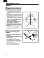
Power Components Service
Disassembly
CAUTION: DO NOT handle the propeller while
the fl ight battery is connected to the ESC. Personal
injury could result.
1. Disconnect the battery from the ESC/receiver.
2. Hold the prop shaft using needle-nose pliers or
hemostats.
3. Turn the propeller counterclockwise (facing the
front of the model) to remove. Turn the propeller
clockwise to install.
4. Carefully remove the damaged spinner and glue
from the propeller.
5. Hold the nut on the end of the prop shaft using
needle-nose pliers or hemostats.
6. Turn the gear on the shaft clockwise (facing the
front of the model) to remove the nut.
7. Gently pull the shaft (A) from the gearbox (B).
Make sure the washer (C) and two bushings (D)
are not lost.
8. Disconnect the motor from the ESC/receiver.
9. Gently push the motor out of the gearbox and
remove the motor from the fuselage.
NOTICE: DO NOT remove the gearbox from the
aircraft. Damage to the aircraft will result.
Assembly
Assemble the aircraft using the instructions above
in reverse order.
• Correctly align the prop shaft gear with the pinion
gear on the motor.
• Connect the motor to the ESC/receiver so
that the powered motor turns the propeller
counterclockwise (facing the front of the model).
• Make sure the propeller size numbers (130 x 70)
face away from the motor.
• Attach the spinner to the propeller using foam-
compatible CA (Cyanoacrylate adhesive).
D
A
B
C
I
n
s
t
a
l
l
R
e
m
o
v
e

11
EN
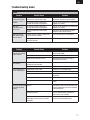
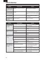
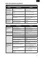
Troubleshooting Guide
AS3X
Problem Possible Cause Solution
Control surfaces not at
neutral position when
transmitter controls are
at neutral
Control surfaces may not have been
mechanically centered from factory
Center control surfaces mechanically by
adjusting the U-bends on control linkages
Aircraft was not kept immobile for 5
seconds after battery was plugged in
Keep the aircraft immobile for 5 seconds after
plugging in the battery
Model fl ies
inconsistently from
fl ight to fl ight
Aircraft was not kept immobile for 5
seconds after battery was plugged in
Keep the aircraft immobile for 5 seconds after
plugging in the battery
Trims are moved too far from neutral
position
Neutralize trims and mechanically adjust
linkages to center control surfaces
Controls oscillate in
fl ight, (model rapidly
jumps or moves)
Propeller, spinner or motor is unbalanced,
causing excessive vibration
Balance parts or replace it if damaged
Nut on prop shaft is too loose, causing
excessive vibration
Tighten the prop shaft nut 1/2 turn
Problem Possible Cause Solution
Aircraft will not respond
to throttle but responds
to other controls
Throttle stick and/or throttle trim too high Reset controls with throttle stick and throttle
trim at lowest setting
Throttle channel is reversed Reverse throttle channel on transmitter
Motor disconnected from receiver Open fuselage and make sure motor is
connected to the receiver
Extra propeller noise or
extra vibration
Propeller, spinner or motor is unbalanced,
causing excessive vibration
Balance parts or replace it if damaged
Prop screw is too loose Tighten the prop screw
Reduced fl ight time or
aircraft underpowered
Flight battery charge is low Completely recharge fl ight battery
Propeller installed backwards Install propeller with numbers facing forward
Flight battery damaged or old. Replace fl ight battery and follow fl ight battery
instructions
Flight conditions may be too cold Make sure battery is warm before use
Battery capacity too low for fl ight conditions Replace battery or use a larger capacity
battery
LED on receiver fl ashes
and aircraft will not bind
to transmitter (during
binding)
Transmitter too near aircraft during binding
process
Power off transmitter, move transmitter a
larger distance from aircraft, disconnect and
reconnect fl ight battery to aircraft and follow
binding instructions
Bind switch or button not held long enough
during bind process
Power off transmitter and repeat bind
process. Hold transmitter bind button or
switch until receiver is bound
Aircraft or transmitter is too close to large
metal object, wireless source or another
transmitter
Move aircraft and transmitter to another
location and attempt binding again

12
EN
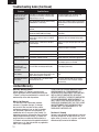
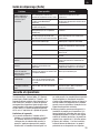
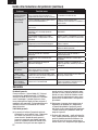
Troubleshooting Guide (Continued)
Problem Possible Cause Solution
LED on receiver fl ashes
rapidly and aircraft
will not respond to
transmitter (after
binding)
Less than a 5-second wait between fi rst
powering on transmitter and connecting
fl ight battery to aircraft
Leaving transmitter on, disconnect and
reconnect fl ight battery to aircraft
Aircraft bound to different model memory
(ModelMatch
™
radios only)
Select correct model memory on transmitter
and disconnect and reconnect fl ight battery
to aircraft
Flight battery/transmitter battery charge is
too low
Replace/recharge batteries
Transmitter may not be compatible with
Spektrum DSM2/DSMX technology
Use a genuine Spektrum DSM2/DSMX
transmitter
Aircraft or transmitter is too close to large
metal object, wireless source or another
transmitter
Move aircraft and transmitter to
anotherlocation and attempt linking again
Control surface does
not move
Control surface, control horn, linkage or
servo damage
Replace or repair damaged parts and adjust
controls
Wires damaged or connections loose Do a check of wires and connections,
connect or replace as needed
Flight battery charge is low Fully recharge fl ight battery
Control linkage does not move freely Make sure control linkage moves freely
Controls reversed Transmitter settings reversed Adjust controls on transmitter appropriately
Motor loses power Damage to motor or power components Do a check of motor and power components
for damage (replace as needed)
Motor power quickly
decreases and
increases then motor
loses power
Battery power is down to the point of
receiver/ESC Low Voltage Cutoff (LVC)
Recharge fl ight battery or replace battery that
is no longer performing
Motor/ESC is not armed
after landing
Over Current Protection (OCP) stops the
motor when the transmitter throttle is set
high and the propeller cannot turn
Fully lower throttle and throttle trim to arm
ESC
Servo locks or freezes
at full travel
Travel adjust value is set above 100%,
overdriving the servo
Set Travel adjust to 100% or less and/or
set sub-trims to Zero and adjust linkages
mechanically
Limited Warranty
What this Warranty Covers
Horizon Hobby, LLC, (Horizon) warrants to the
original purchaser that the product purchased (the
“Product”) will be free from defects in materials and
workmanship at the date of purchase.
What is Not Covered
This warranty is not transferable and does
not cover (i) cosmetic damage, (ii) damage
due to acts of God, accident, misuse, abuse,
negligence, commercial use, or due to improper
use, installation, operation or maintenance, (iii)
modifi cation of or to any part of the Product, (iv)
attempted service by anyone other than a Horizon
Hobby authorized service center, (v) Product not
purchased from an authorized Horizon dealer, or
(vi) Product not compliant with applicable technical
regulations, or (vii) use that violates any applicable
laws, rules, or regulations.
OTHER THAN THE EXPRESS WARRANTY ABOVE,
HORIZON MAKES NO OTHER WARRANTY OR
REPRESENTATION, AND HEREBY DISCLAIMS ANY
AND ALL IMPLIED WARRANTIES, INCLUDING,
WITHOUT LIMITATION, THE IMPLIED WARRANTIES
OF NON-INFRINGEMENT, MERCHANTABILITY
AND FITNESS FOR A PARTICULAR PURPOSE. THE
PURCHASER ACKNOWLEDGES THAT THEY ALONE
HAVE DETERMINED THAT THE PRODUCT WILL
SUITABLY MEET THE REQUIREMENTS OF THE
PURCHASER’S INTENDED USE.
Purchaser’s Remedy
Horizon’s sole obligation and purchaser’s sole and
exclusive remedy shall be that Horizon will, at its
option, either (i) service, or (ii) replace, any Product
determined by Horizon to be defective.

13
EN
Horizon reserves the right to inspect any and all
Product(s) involved in a warranty claim. Service or
replacement decisions are at the sole discretion
of Horizon. Proof of purchase is required for all
warranty claims. SERVICE OR REPLACEMENT
AS PROVIDED UNDER THIS WARRANTY IS THE
PURCHASER’S SOLE AND EXCLUSIVE REMEDY.
Limitation of Liability
HORIZON SHALL NOT BE LIABLE FOR SPECIAL,
INDIRECT, INCIDENTAL OR CONSEQUENTIAL
DAMAGES, LOSS OF PROFITS OR PRODUCTION OR
COMMERCIAL LOSS IN ANY WAY, REGARDLESS OF
WHETHER SUCH CLAIM IS BASED IN CONTRACT,
WARRANTY, TORT, NEGLIGENCE, STRICT LIABILITY
OR ANY OTHER THEORY OF LIABILITY, EVEN IF
HORIZON HAS BEEN ADVISED OF THE POSSIBILITY
OF SUCH DAMAGES. Further, in no event shall
the liability of Horizon exceed the individual price
of the Product on which liability is asserted. As
Horizon has no control over use, setup, fi nal
assembly, modifi cation or misuse, no liability
shall be assumed nor accepted for any resulting
damage or injury. By the act of use, setup or
assembly, the user accepts all resulting liability. If
you as the purchaser or user are not prepared to
accept the liability associated with the use of the
Product, purchaser is advised to return the Product
immediately in new and unused condition to the
place of purchase.
Law
These terms are governed by Illinois law (without
regard to confl ict of law principals). This warranty
gives you specifi c legal rights, and you may also
have other rights which vary from state to state.
Horizon reserves the right to change or modify this
warranty at any time without notice.
WARRANTY SERVICES
Questions, Assistance, and Services
Your local hobby store and/or place of purchase
cannot provide warranty support or service. Once
assembly, setup or use of the Product has been
started, you must contact your local distributor or
Horizon directly. This will enable Horizon to better
answer your questions and service you in the event
that you may need any assistance. For questions
or assistance, please visit our website at www.
horizonhobby.com, submit a Product Support
Inquiry, or call the toll free telephone number
referenced in the Warranty and Service Contact
Information section to speak with a Product Support
representative.
Inspection or Services
If this Product needs to be inspected or serviced
and is compliant in the country you live and use
the Product in, please use the Horizon Online
Service Request submission process found on
our website or call Horizon to obtain a Return
Merchandise Authorization (RMA) number. Pack the
Product securely using a shipping carton. Please
note that original boxes may be included, but are
not designed to withstand the rigors of shipping
without additional protection. Ship via a carrier
that provides tracking and insurance for lost or
damaged parcels, as Horizon is not responsible for
merchandise until it arrives and is accepted at our
facility. An Online Service Request is available at
http://www.horizonhobby.com/content/_service-
center_render-service-center. If you do not have
internet access, please contact Horizon Product
Support to obtain a RMA number along with
instructions for submitting your product for service.
When calling Horizon, you will be asked to provide
your complete name, street address, email address
and phone number where you can be reached
during business hours. When sending product into
Horizon, please include your RMA number, a list
of the included items, and a brief summary of the
problem. A copy of your original sales receipt must
be included for warranty consideration. Be sure
your name, address, and RMA number are clearly
written on the outside of the shipping carton.
NOTICE: Do not ship LiPo batteries to Horizon.
If you have any issue with a LiPo battery,
please contact the appropriate Horizon Product
Support offi ce.
Warranty Requirements
For Warranty consideration, you must include
your original sales receipt verifying the proof-
of-purchase date. Provided warranty conditions
have been met, your Product will be serviced or
replaced free of charge. Service or replacement
decisions are at the sole discretion of Horizon.
Non-Warranty Service
Should your service not be covered by warranty,
service will be completed and payment will be
required without notifi cation or estimate of the
expense unless the expense exceeds 50% of the
retail purchase cost. By submitting the item for
service you are agreeing to payment of the service
without notifi cation. Service estimates are available
upon request. You must include this request with
your item submitted for service. Non-warranty
service estimates will be billed a minimum of ½
hour of labor. In addition you will be billed for return
freight. Horizon accepts money orders and cashier’s
checks, as well as Visa, MasterCard, American
Express, and Discover cards. By submitting any
item to Horizon for service, you are agreeing to
Horizon’s Terms and Conditions found on our
website http://www.horizonhobby.com/content/_
service-center_render-service-center.
ATTENTION: Horizon service is limited to
Product compliant in the country of use and
ownership. If received, a non-compliant Product
will not be serviced. Further, the sender will be
responsible for arranging return shipment of the
un-serviced Product, through a carrier of the
sender’s choice and at the sender’s expense.
Horizon will hold non-compliant Product for a
period of 60 days from notifi cation, after which
it will be discarded.
10/15

14
EN
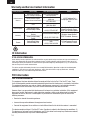
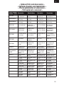
Warranty and Service Contact Information
Country of Purchase Horizon Hobby Phone Number/Email Address Address
United States of
America
Horizon Service Center
(Repairs and Repair Requests)
servicecenter.horizonhobby.
com/RequestForm/
4105 Fieldstone Rd
Champaign, Illinois, 61822
USA
Horizon Product Support
(Product Technical Assistance)
productsupport@horizon-
hobby.com
877-504-0233
Sales
websales@horizonhobby.com
800-338-4639
United Kingdom
Service/Parts/Sales:
Horizon Hobby Limited
sales@horizonhobby.co.uk Units 1–4 , Ployters Rd,
Staple Tye Harlow, Essex,
CM18 7NS, United Kingdom
+44 (0) 1279 641 097
Germany
Horizon Technischer
Service
service@horizonhobby.de
Christian-Junge-Straße 1
25337 Elmshorn, Germany
Sales: Horizon Hobby
GmbH
+49 (0) 4121 2655 100
France
Service/Parts/Sales:
Horizon Hobby SAS
infofrance@horizonhobby.
com
11 Rue Georges Charpak
77127 Lieusaint, France
+33 (0) 1 60 18 34 90
FCC Information
This equipment has been tested and found to comply with the limits for Part 15 of the FCC rules. These
limits are designed to provide reasonable protection against harmful interference in a residential installation.
This equipment generates uses and can radiate radio frequency energy and, if not installed and used in
accordance with the instructions, may cause harmful interference to radio communications.
However, there is no guarantee that interference will not occur in a particular installation. If this equipment
does cause harmful interference to radio or television reception, which can be determined by turning the
equipment off and on, the user is encouraged to try to correct the interference by one or more of the
following measures:
• Reorient or relocate the receiving antenna.
• Increase the separation between the equipment and receiver.
• Connect the equipment to an outlet on a circuit different from that to which the receiver is connected.
This device complies with part 15 of the FCC rules. Operation is subject to the following two conditions: (1)
This device may not cause harmful interference, and (2) this device must accept any interference received,
including interference that may cause undesired operatio
IC Information
Under Industry Canada regulations, this radio transmitter may only operate using an antenna of a type and maximum (or
lesser) gain approved for the transmitter by Industry Canada. To reduce potential radio interference to other users, the
antenna type and its gain should be so chosen that the equivalent isotropically radiated power (e.i.r.p.) is not more than
that necessary for successful communication.
This device complies with Industry Canada licence-exempt RSS standard(s). Operation is subject to the following two
conditions: (1) this device may not cause interference, and (2) this device must accept any interference, including
interference that may cause undesired operation of the device.”
IC ID: 6157A-SPMAS6410L
FCC ID: BRWSPMAS6410L

15
EN
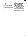
Compliance Information for the European Union
EFL UMX Yak 54 3D BNF Basic (EFLU3550)
EU Compliance Statement: Horizon Hobby, LLC
hereby declares that this product is in compliance
with the essential requirements and other relevant
provisions of the RED Directive.
A copy of the EU Declaration of Conformity is
available online at: http://www.horizonhobby.com/
content/support-render-compliance.
Instructions for disposal of WEEE by
users in the European Union
This product must not be disposed
of with other waste. Instead, it is the
user’s responsibility to dispose of their
waste equipment by handing it over
to a designated collections point for
the recycling of waste electrical and electronic
equipment. The separate collection and recycling
of your waste equipment at the time of disposal
will help to conserve natural resources and ensure
that it is recycled in a manner that protects human
health and the environment. For more information
about where you can drop off your waste equipment
for recycling, please contact your local city offi ce,
your household waste disposal service or where you
purchased the product.

16
DE
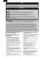
WARNUNG: Lesen Sie die GESAMTE Bedienungsanleitung, um sich vor Inbetriebnahme mit den
Funktionen des Produkts vertraut zu machen. Eine nicht ordnungsgemäße Bedienung des Produkts kann
das Produkt und persönliches Eigentum schädigen und schwere Verletzungen verursachen.
Dies ist ein hoch entwickeltes Produkt für den Hobbygebrauch. Es muss mit Vorsicht und Umsicht
bedient werden und erfordert einige mechanische Grundfertigkeiten. Wird das Produkt nicht sicher
und umsichtig verwendet, so könnten Verletzungen oder Schäden am Produkt oder anderem Eigentum
entstehen. Dieses Produkt ist nicht für den Gebrauch durch Kinder ohne direkte Aufsicht eines
Erwachsenen vorgesehen. Versuchen Sie nicht, das Produkt ohne Zustimmung von Horizon Hobby, LLC
zu zerlegen, mit nicht-kompatiblen Komponenten zu verwenden oder beliebig zu verbessern. Dieses
Handbuch enthält Sicherheitshinweise sowie Anleitungen zu Betrieb und Wartung. Es ist unerlässlich,
dass Sie alle Anleitungen und Warnungen in diesem Handbuch vor dem Zusammenbau, der Einrichtung
oder der Inbetriebnahme lesen und diese befolgen, um eine korrekte Bedienung zu gewährleisten und
Schäden bzw. schwere Verletzungen zu vermeiden.
Altersempfehlung: Nicht für Kinder unter 14
Jahren. Dies ist kein Spielzeug.
Sicherheitsmaßnahmen und
Warnungen
• Halten Sie stets in allen Richtungen einen
Sicherheitsabstand zu Ihrem Modell ein, um
Kollisionen und Verletzungen zu vermeiden.
Dieses Modell wird über ein Funksignal
gesteuert. Funksignale können von außerhalb
gestört werden, ohne dass Sie darauf Einfl uss
nehmen können. Störungen können zu einem
vorübergehenden Verlust der Steuerungskontrolle
führen.
• Betreiben Sie Ihr Modell stets auf offenen
Geländen, weit ab von Autos, Verkehr und
Menschen.
• Befolgen Sie die Anweisungen und Warnungen
für dieses Produkt und jedwedes optionales
Zubehörteil (Ladegeräte, wieder aufl adbare Akkus
etc.) stets sorgfältig.
• Halten Sie sämtliche Chemikalien, Kleinteile und
elektrische Komponenten stets außer Reichweite
von Kindern.
• Vermeiden Sie den Wasserkontakt aller
Komponenten, die nicht speziell dafür ausgelegt
und entsprechend geschützt sind. Feuchtigkeit
beschädigt die Elektronik.
• Nehmen Sie niemals ein Element des Modells in
Ihren Mund, da dies zu schweren Verletzungen
oder sogar zum Tod führen könnte.
• Betreiben Sie Ihr Modell niemals mit schwachen
Senderbatterien.
• Behalten Sie das Modell stets im Blick und unter
Kontrolle.
• Verwenden Sie nur vollständig aufgeladene
Akkus.
• Behalten Sie den Sender stets eingeschaltet,
wenn das Modell eingeschaltet ist.
• Entfernen Sie stets den Akku, bevor Sie das
Modell auseinandernehmen.
• Halten Sie bewegliche Teile stets sauber.
• Halten Sie die Teile stets trocken.
• Lassen Sie die Teile stets auskühlen, bevor Sie
sie berühren.
• Entfernen Sie nach Gebrauch stets den Akku.
• Stellen Sie immer sicher, dass der Failsafe vor
dem Flug ordnungsgemäß eingestellt ist.
• Betreiben Sie das Modell niemals bei
beschädigter Verkabelung.
• Berühren Sie niemals sich bewegende Teile.
Begriffserklärung:
Die folgenden Begriffe werden in der gesamten Produktliteratur verwendet, um die Gefährdungsstufen
im Umgang mit dem Produkt zu defi nieren:
HINWEIS: Verfahren, die bei nicht ordnungsgemäßer Durchführung womöglich Schäden an
physischem Eigentum UND geringfügige oder keine Verletzungen verursachen können.
ACHTUNG: Verfahren, die bei nicht ordnungsgemäßer Durchführung womöglich Schäden an
physischem Eigentum UND schwere Verletzungen verursachen können.
WARNUNG: Verfahren, die bei nicht ordnungsgemäßer Durchführung womöglich Schäden an
Eigentum, Kollateralschäden und schwere Verletzungen ODER höchstwahrscheinlich oberfl ächliche
Verletzungen verursachen können.
HINWEIS
Allen Anweisungen, Garantien und anderen zugehörigen Dokumenten sind Änderungen nach Ermessen
von Horizon Hobby, LLC vorbehalten. Aktuelle Produktliteratur fi nden Sie unter www.horizonhobby.com
im Support-Abschnitt für das Produkt.

17
DE
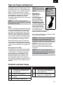
Registrieren Sie Ihr Produkt online unter unter www.e-fl iterc.com
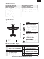
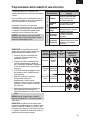
36 g
Inhaltsverzeichnis
Spezifi kationen
Flügelfl äche:
472,3 cm
2
1. Laden Sie den Flugakku.
2. Setzen Sie einen vollständig geladenen
Flugakku ein.
3. Binden Sie das Modell an den Sender.
4. Stellen Sie sicher, dass die Anlenkungen
und Gestänge frei laufen.
5. Führen Sie mit dem Sender einen
Steuerrichtungstest durch.
6. Stellen Sie die Dual Rates ein.
7. Justieren Sie den Schwerpunkt.
8. Führen Sie einen Reichweitentest durch.
9. Suchen Sie ein sicheres und offenes
Fluggelände.
10. Planen Sie Ihren Flug nach den
Flugfeldbedingungen.
Checkliste vor dem Fliegen
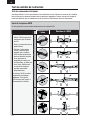
Eingebaut
Motor: Ultra-Micro-Bürstenmotor
8,5mm x 23mm (EFLU5152)
Empfänger: DSM2/DSMX UM AS3X
®
Empfänger/Servos/ESC (EFLU5164)
(2) 2,3 g Performance-Linearservo mit
langem Ruderweg (SPMSA2030L)
Erforderlich
Akku: 150mAh 1S 3,7V 25C/45C
LiPo, (EFLB1501S25 oder EFLB1501S45)
Ladegerät:
Celectra™ 4-Port-LiPo-Ladegerät 1S
3,7V 0,3A DC (EFLC1004)
Empfohlener Sender:
Spektrum™ DSM2
®
/DSMX
®
mit Dual
Rates und voller Reichweite (DX4e und
höher)
497mm
430mm
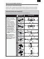
Binden von Sender und Empfänger .....................18
Niederspannungsabschaltung (LVC) ....................18
Wechseln der Flugzustände ................................19
Armieren von ESC/Empfänger, Einsetzen des Akkus
und Schwerpunkt ...............................................20
Steuerrichtungstests ........................................... 21
Zentrieren der Ruderfl ächen ...............................22
Trimmung ...........................................................22
Einstellungen der Ruderhörner ............................22
Dual Rates und Expos .........................................22
Tipps zum Fliegen und Reparieren ......................23
Checkliste nach dem Fliegen ..............................23
Wartung der Antriebskomponenten .....................24
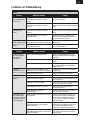
Leitfaden zur Problemlösung ...............................25
Garantie und Serviceinformationen .....................26
Kontaktinformationen ..........................................28
Konformitätshinweise für die Europäische Union .28
Ersatzteile ............................................................ 54
Optionale Bauteile und Zubehörteile .....................55

18
DE
Eine Aufl istung der DSM2/DSMX-kompatiblen Sender fi nden Sie unter www.bindnfl y.com.
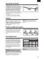
Binden von Sender und Empfänger
Für nachfolgende Flüge schalten Sie den Sender 5 Sekunden vor dem Anschließen des Flugakkus ein.
Bindevorgang
ACHTUNG: Wenn Sie einen Futaba Sender mit einem Spektrum DSM
®
-Modul verwenden, müssen
Sie den Gaskanal reversieren (umkehren) und danach das System neu binden. Lesen Sie bitte für den
Bindevorgang und das Programmieren der Failsafe-Einstellungen die Bedienungsanleitung des Spektrum
Modules. Zum Reversieren des Gaskanals lesen Sie bitte in der Anleitung des Futaba Senders nach.
1. Lesen Sie in der Anleitung Ihres Senders die Anweisungen zum Bindevorgang nach (Position
des Bindeknopfes).
2. Stellen Sie sicher, dass der Flugakku vom Flugzeug getrennt ist.
3. Stellen Sie sicher, dass der Sender ausgeschaltet ist.
4. Schließen Sie den Flugakku an das Flugzeug an und positionieren Sie das Flugzeug aufrecht.
Die LED auf dem Empfänger beginnt zu blinken (nach 5 Sekunden etwa).
5. Bitte stellen Sie sicher, dass alle Steuerflächen-Trimmungen zentriert sind und Gas sowie die
Gastrimmung in der untersten möglichen Position sind, um so das Failsafe einzustellen.
6. Aktivieren Sie den Bindemode Ihres Senders. Für Informationen zu Bindeknopf oder -schalter
lesen Sie bitte in der Anleitung Ihres Senders nach.
7. Nach 5 bis 10 Sekunden leuchtet die Empfänger-LED und zeigt damit an, dass der Empfänger
an den Sender gebunden ist. Sollte die LED nicht konstant leuchten, lesen Sie bitte im Leitfaden
zur Problemlösung am Ende der Anleitung nach.
Wird ein LiPo-Akku unter 3 Volt per Zelle
entladen, kann er keine Ladung mehr halten.
Der Regler schützt den Flugakku mit der
Niederspannungsabschaltung vor Tiefentladung.
Sobald eine Zellenspannung von 3 Volt erreicht
ist, wird die Motorleistung reduziert, um noch
ausreichend Restleistung für Servos und Empfänger
für eine sichere Landung zur Verfügung zu stellen.
Sollte der Motor zu pulsieren beginnen, landen Sie
das Flugzeug unverzüglich und laden oder ersetzen
Sie den Flugakku.
Trennen Sie den LiPo-Akku immer nach dem
Fliegen und nehmen Sie ihn aus dem Modell. Laden
Sie den LiPo-Akku auf die Hälfte seiner Kapazität,
bevor Sie ihn einlagern. Stellen Sie sicher, dass
die Spannung nicht unter 3 Volt pro Zelle fällt.
Wenn Sie den Akku nicht entfernen, kommt es zur
Tiefentladung des Akkus.
Stellen Sie für Ihre ersten Flüge den Timer Ihres
Senders auf 4 Minuten. Justieren Sie den Timer
für längere oder kürzere Flüge erst, wenn Sie das
Modell gefl ogen haben.
HINWEIS: Wiederholtes Fliegen in die
Niederspanungsabschaltung (LVC) beschädigt den
Akku.
Niederspannungsabschaltung (LVC)

19
DE
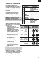
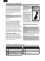
Wechseln der Flugzustände
Standard-
Flight-
Mode
Alternativer
Flight Mode
Schalter-
position
CH 5
Knüppelpositionen
(Mode 2 abgebildet)
Allgemein
Standard-
AS3X
®
-
Technologie
0
Standard-
AS3X
®
Messerfl ug-
Unterstützung
1
Hover-
Unterstützung
Torquerollen-
Unterstützung
2
Auf Standardeinstellungen
zurücksetzen
Das Flugzeug ist standardmäßig mit 3
Flugzuständen (Flight Modes) programmiert, die in
der rechten Tabelle fettgedruckt aufgeführt sind.
Ein Sender mit einem 2-Positionsschalter für Kanal
5 ermöglicht lediglich die Positionen 0 und 2 der
Flugzustände.
Falls möglich (siehe Bedienungsanleitung
des Senders), weisen Sie Kanal 5 einen
3-Positionsschalter zu, um alle 3 Flugzustände
nutzen zu können. Sie können die Flugzustände mit
den unten stehenden Anweisungen auch ändern.
HINWEIS: Ein schneller Vorwärtsflug in den
Flugmodes mit Torquerollen- und Hover-
Unterstützung kann zu Schwingungen führen und
das Flugzeug beschädigen.
WICHTIG: Ihr Sender muss an den Empfänger
gebunden sein, bevor Sie die Programmierung der
Flight Modes ändern.
1. Versichern Sie sich, dass die
Servoreverse-Einstellungen im Sender
auf Normal gestellt sind.
2. Halten Sie die Sendersteuerhebel wie
abgebildet und schließen Sie dann den
Flugakku an. Der dem Flugzustand
zugeordnete Schalter muss dafür in
keiner bestimmten Position sein.
3. Die Empfänger-LED blinkt 3 Mal, um
die Änderung des Flugzustands zu
bestätigen.
4. Nach dem Wechsel einer
Schalterposition bringen Sie das Gas
vollständig auf Leerlauf und trennen
dann den Akku. Der Empfänger
speichert dann den neuen Flugzustand
für die nächsten Flüge.
5. Wiederholen Sie den Vorgang, um in
andere Flight Modes zu wechseln, oder
setzen Sie alle Einstellungen mit Hilfe
der Abbildung zurück.
HINWEIS: Starten Sie das Flugzeug immer im
Modus Allgemein oder Standard-AS3X
®
, da es sonst
beschädigt werden könnte.
WICHTIG: Wird der Gashebel für 1-2 Sekunden
vollständig nach unten gebracht, wird das Flugzeug
in den Standard-AS3X-Mode zurückgesetzt, bis
wieder erneut Gas gegeben wird. Das ist normal.
Der Standard-AS3X-Mode ermöglicht das Starten
des Flugzeugs, ohne dass ein Steuerbefehl gehalten
werden muss.
Flugzustand Eigenschaften
Standard
Allgemein
Heading Hold auf
Querruder, Standard-
AS3X auf Höhenruder und
Seitenruder.
Standard-AS3X
Standard AS3X auf
Querruder, Höhenruder und
Seitenruder.
Hover-
Unterstützung
Aggressives Heading Hold
auf Querruder, Höhenruder
und Seitenruder.
Alternativ
Messerfl ug-
Unterstützung
Heading Hold auf
Querruder, Höhenruder und
Seitenruder.
Torquerollen-
Unterstützung
Standard-AS3X auf
Querruder, aggressives
Heading Hold auf
Höhenruder und
Seitenruder.

20
DE
1-2-3-4-5 Sec.
3
4
1
2
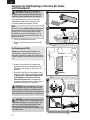
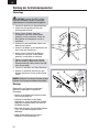
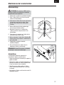
Armieren von ESC/Empfänger, Einsetzen des Akkus
und Schwerpunkt
ACHTUNG: Halten Sie die Hände stets in
gebührendem Abstand vom Propeller. Im
scharfgeschalteten Zustand dreht der Motor den
Propeller bei jeder Bewegung des Gasknüppels.
Der Regler/Empfänger armiert sich nach dem
Bindevorgang. Jeder weitere Anschluss eines
Flugakkus erfordert die folgenden Schritte.
AS3X
Das AS3X
®
-System aktiviert sich erst dann, wenn
der Gashebel zum ersten Mal erhöht wird. Einmal
aktiviert, kann es dazu kommen, dass sich die
Ruderfl ächen schnell und laut bewegen. Das ist
normal. Das AS3X-System bleibt aktiviert bis der
Akku getrennt wird.
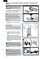
1. Kleben Sie Klettband auf den Akku.
2. Setzen Sie den Akku auf den Klettstreifen am
Rumpf.
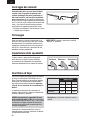
Der Schwerpunkt (CG)
94mm von der Hinterkante der Tragfl äche, wo
die Tragfl äche auf den Rumpf trifft, nach vorne
gemessen. Markieren Sie diese Stelle. Balancieren
Sie das Flugzeug auf dem markierten Schwerpunkt
aus.
3. Senken Sie den Gasstick auf Leerlauf und
die Gastrimmung auf die niedrigste Stellung.
Schalten Sie den Sender ein und warten Sie 5
Sekunden.
4. Schließen Sie den Akku an den Regler an und
achten Sie dabei auf die korrekte Polarität. Das
Flugzeug muss 5 Sekunden windgeschützt
und vollkommen still stehen, damit das
AS3X initialisieren kann. Die erfolgreiche
Verbindung wird durch mehrere Töne und das
konstante Leuchten der LED angezeigt.
ACHTUNG: Trennen Sie stets den LiPo-Akku
vom Regler, wenn Sie nicht fl iegen, um die
Stromversorgung zum Motor zu unterbrechen. Der
Regler hat keinen Ein/Aus-Schalter und reagiert auf
jeden Gasbefehl vom Sender, wenn ein Signal da ist.
ACHTUNG: Trennen Sie immer den LiPo-Akku
vom Flugzeug, wenn Sie nicht fl iegen, um ein
Tiefentladen des Akkus zu vermeiden. Akkus, die
unter die zulässige Mindestspannung entladen
werden, können beschädigt werden, was zu
Leistungsverlust und potenzieller Brandgefahr beim
Laden führen kann.
94mm
Seite wird geladen ...
Seite wird geladen ...
Seite wird geladen ...
Seite wird geladen ...
Seite wird geladen ...
Seite wird geladen ...
Seite wird geladen ...
Seite wird geladen ...
Seite wird geladen ...
Seite wird geladen ...
Seite wird geladen ...
Seite wird geladen ...
Seite wird geladen ...
Seite wird geladen ...
Seite wird geladen ...
Seite wird geladen ...
Seite wird geladen ...
Seite wird geladen ...
Seite wird geladen ...
Seite wird geladen ...
Seite wird geladen ...
Seite wird geladen ...
Seite wird geladen ...
Seite wird geladen ...
Seite wird geladen ...
Seite wird geladen ...
Seite wird geladen ...
Seite wird geladen ...
Seite wird geladen ...
Seite wird geladen ...
Seite wird geladen ...
Seite wird geladen ...
Seite wird geladen ...
Seite wird geladen ...
Seite wird geladen ...
Seite wird geladen ...
-
 1
1
-
 2
2
-
 3
3
-
 4
4
-
 5
5
-
 6
6
-
 7
7
-
 8
8
-
 9
9
-
 10
10
-
 11
11
-
 12
12
-
 13
13
-
 14
14
-
 15
15
-
 16
16
-
 17
17
-
 18
18
-
 19
19
-
 20
20
-
 21
21
-
 22
22
-
 23
23
-
 24
24
-
 25
25
-
 26
26
-
 27
27
-
 28
28
-
 29
29
-
 30
30
-
 31
31
-
 32
32
-
 33
33
-
 34
34
-
 35
35
-
 36
36
-
 37
37
-
 38
38
-
 39
39
-
 40
40
-
 41
41
-
 42
42
-
 43
43
-
 44
44
-
 45
45
-
 46
46
-
 47
47
-
 48
48
-
 49
49
-
 50
50
-
 51
51
-
 52
52
-
 53
53
-
 54
54
-
 55
55
-
 56
56


Horizon Hobby UMX YAK 54 3D Benutzerhandbuch
- Kategorie
- Ferngesteuertes Spielzeug
- Typ
- Benutzerhandbuch
in anderen Sprachen
Verwandte Artikel
Andere Dokumente
-
E-flite UMX PT-17 Benutzerhandbuch
-
-
E-flite Carbon-Z Cub Benutzerhandbuch
-
-
-
HobbyZone HBZ5700 Bedienungsanleitung
-
-
BNF P-51D Mustang 280 Benutzerhandbuch
-
Blade AH-64 Apache Benutzerhandbuch
-
E-flite EFLU3080 Bedienungsanleitung