Simplicity QVSPEU Benutzerhandbuch
- Kategorie
- Spielzeuge
- Typ
- Benutzerhandbuch

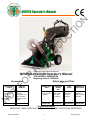
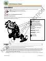
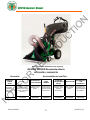
QVSPEU Operator’s Manual
Part No 831507 1 831507_E_HI
Image shown with optional accessories
QVSPEU VACUUM Operator's Manual
QV550HSPEU, QV900HSPEU
Beginning Serial #: 122020001
Accessories Debris bags and Filter
(INCLUDED)
Original Instructions
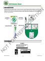
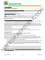
IMPORTANT- READ CAREFULLY BEFORE USE AND KEEP FOR FUTURE REFERENCE.
STANDARD
DEBRIS
BAG
Standard on
QV models.
For dusty
conditions.
P/N 831613
DEBRIS AND
DUST SOCK
Traps dust
keeping it
away from the
operator.
P/N 831282
VACUUM
HOSE KIT
5" (127mm) x
10' (3m)
collapsible hose
for vacuuming
in hard-to-reach
areas
P/N 831018
HOOD
FILTER
Filters out
dust from
vacuum
exhaust.
P/N 831226
DEBRIS BAG
SKIRT
Directs dust
away from the
operator.
P/N 831268
ADJUSTABLE
HANDLE
Allows for the
handle to be
raised or
lowered for
comfort.
P/N 831614
NOT FOR REPRODUCTION

QVSPEU Operator’s Manual
Part No 831507 831507_E_HI
2
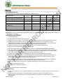
CONTENTS
SPECIFICATIONS 3
INSTRUCTION LABELS 4
PACKING CHECKLIST AND ASSEMBLY 5
OPERATION AND BAG CARE 6-7
MAINTENANCE AND TROUBLESHOOTING 8-9
ILLUSTRATED PARTS & PARTS LISTS 10-13
NOT FOR REPRODUCTION

QVSPEU Operator’s Manual
Part No 831507 831507_E_HI
3
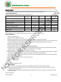
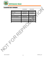
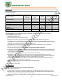
SPECIFICATIONS
QV550HSPEU QV900HSPEU
HP 5.5 (4.1 kW) 9.0 HP (6.6kW)
Engine: Type X160UT2QX2 GX270UT2XQA2
Engine: Fuel Capacity 3.88 qt. (3.6 L) 6.3 qt. (6.0L)
Engine: Oil Capacity 0.69 qt. (0.65 L) 1.16 qt. (1.1L)
Total Unit Weight: 226# (102.5 kg) 248# (112.5 kg)
Overall Length 63” (1.6m) 63” (1.6m)
Overall Width 33” (0.84m) 33” (0.84m)
Overall Height 51” (1.3 m) 51” (1.3 m)
Max. operating slope 200 200
NOT FOR REPRODUCTION

QVSPEU Operator’s Manual
Part No 831507 831507_E_HI
4
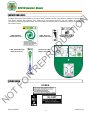
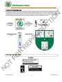
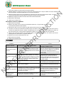
INSTRUCTION LABELS
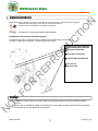
The labels shown below were installed on your BILLY GOAT® QVSPEU Vacuum. If any labels are damaged or missing, replace
them before operating this equipment. Item numbers from the Illustrated Parts List and part numbers are provided for
convenience in ordering replacement labels. The correct position for each label may be determined by referring to the Figure and
Item numbers shown.
LABEL WARNING LABEL THROTTLE LABEL DANGER GUARDS
ITEM #35 P/N 831265 ITEM #106 P/N 810656 ITEM #106 P/N 900327
LABEL DRIVE DIRECTION INSTRUCTION LABEL
ITEM # 38 P/N 831270 ITEM # 37 P/N 831258
ENGINE LABELS
HONDA
NOT FOR REPRODUCTION

QVSPEU Operator’s Manual
Part No 831507 831507_E_HI
5
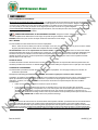
PACKING CHECKLIST
Your Billy Goat is shipped from the factory in one carton, completely assembled except for the nozzle and handle.
PUT OIL IN ENGINE BEFORE STARTING
ASSEMBLY
READ all safety instructions before assembling unit.
TAKE CAUTION when removing the unit from the box.
NOTE: Items in ( ) can be referenced in the Parts Illustrations and Parts Lists on pages 10-13.
1. REMOVE the unit from the box. Be careful as cables could snag.
2. REMOVE the bag and attach the handle to the hood using the hardware from the parts bag. The large washer should be
on the inside and the bolt should run from the inside of the hood out. The arch of the handle should be facing to the front of
the machine and the cables shoud not be twisted around each other. NOTE: The left cable should run to the right side of
the transmission and right cable to the left of the transmission. Cable twisting will interfere with the operation of the
machine and will cause premature cable wear.
3. ATTACH the front nozzle (item 7) to the housing and secure it with the serrated hex nuts (item 58) located in the parts bag.
Boxing Parts Checklist
Debris Bag P/N-831225
Dust Sock P/N-831268
Front Nozzle P/N-831606
Literature Assy P/N-831019
Screwcap 5/16”-18 x 1 3/4 qty 4
P/N-8041031
Washer 2” OD x .344 ID qty 4
P/N-810652
Washer 5/16” Flat qty 4
P/N-8171003
Nut Lock 5/16” – 18 qty 4
P/N-8160002
Honda 9 HP
Honda 5.5 HP
PARTS BAG & LITERATURE ASSY
Warranty card P/N- 80102772, Operator’s Manual P/N-831507, Declaration of Conformity P/N-100506. General
Safety and Warnings Manual P/N-100294
NOT FOR REPRODUCTION

QVSPEU Operator’s Manual
Part No 831507 831507_E_HI
6
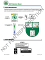
OPERATION
VACUUM OPERATION
WARNING: The maximum RPM’s on the unit’s engine are set. Altering them from the factory settings could
potentially damage the unit and void warranty.
VACUUM NOZZLE HEIGHT ADJUSTMENT: Adjust by turning the knob clockwise to increase height and counter-clockwise to
lower it. Adjust nozzle height according to surface conditions and debris size. For vacuuming on flat surfaces, set nozzle 1/2"
(12.7 mm) to 5/8" (15.8 mm) above ground. Adjust higher for uneven terrain and turf.
FOR MAXIMUM PICKUP: Adjust nozzle close to debris, but without blocking airflow into the nozzle. NOTE: Never bury nozzle
into debris.
CLEARING A CLOGGED NOZZLE & EXHAUST: Turn engine off and wait for impeller to stop completely and
disconnect spark plug wire. Wearing durable gloves, remove clog.
DANGER, the clog may contain sharp materials. Reconnect spark plug wire.
PROPULSION
First set the forward or reverse lever to the desired position. (Having the lever straight up will put the unit into neutral). To drive
in a straight path squeeze both levers, for turning right squeeze the right lever only and likewise to turn left, squeeze the left
lever. When no levers are engaged the unit will freewheel. DO NOT partially engage the transmission when engaging the levers.
The levers must be completely engaged. Prolonged use of partial engagement could cause internal damage to transmission.
DEBRIS BAG
Debris bags are normal replaceable wear items.
NOTE: Frequently empty debris to prevent bag overloading with more weight than you can lift. Use the dust skirt when
debris will be vacuumed in dusty conditions.
DO NOT place bag on or near hot surface, such as engine. Run engine at 1/2 throttle for first 1/2 hour to condition new bag.
Your new bag requires a break-in period to condition the pores of the material against premature blockage. The entire bag
surface serves as a filter, and must be able to breathe to have good vacuum performance. Be sure engine has come to a
complete stop before removing or emptying bag.
HOOD FILTER
Hood filters are normal replaceable wear items. The hood filter is for use in dry dusty conditions only. DO NOT get the filter wet.
Clean with light compressed air only.
DUST SOCK
Dust socks are normal replaceable wear items. See dust sock care next page.
DUSTY CONDITIONS
This vacuum is designed for picking up trash, organic material and other similar debris. However, many vacuums are used
where dust is mixed with trash. Your unit can intermittently vacuum in dusty areas. Dust is the greatest cause of lost vacuum
performance. However, following these rules will help maintain your machine's ability to vacuum in dusty conditions:
• Run machine at idle to quarter throttle.
• The debris bag must be cleaned more frequently. A vacuum with a clean, pillow soft bag will have good pickup
performance. One with a dirty, tight bag will have poor pickup performance. If dirty, empty debris and vigorously shake
bag free of dust. Having one or more spare debris bags is a good way to reduce down time while dirty bags are being
cleaned. DO NOT leave debris in bag while in storage.
NOT FOR REPRODUCTION

QVSPEU Operator’s Manual
Part No 831507 831507_E_HI
7
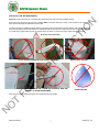
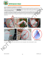
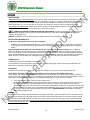
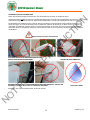
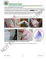
DUST SOCK CARE AND MAINTENANCE
Purpose: The dust sock acts as a secondary filter lowering the amount of dust that escapes the bag.
Dust socks are to be used in dry and dusty conditions ONLY. Using the dust sock in damp or wet conditions may damage the
dust sock and decrease the effectiveness of the filter.
The dust sock may be installed by simply attaching the mating Velcro strips between the bag and the dust sock. Over time the
dust sock will begin to fill with dust during use. Periodically remove the dust sock, empty the loose dust out and clean the sock.
For a light clean, simply shake the sock, for a deep clean, see below. To remove the sock, simply separate the Velcro.
Dust Sock Care Information:
DO NOT STRIKE THE BAG WITH OR AGAINST OBJECTS DO NOT SNAG THE BAG
DO NOT GET WET
Dust socks are normal replaceable wear items. Replacement P/N- 831282
LIGHTLY CLEAN WITH COMPRESSED AIR ONLY, FROM THE OUTSIDE IN. KEEP THE
NOZZLE 6-12 INCHES FROM FABRIC
6”-12”
(152mm-305mm)
NOT FOR REPRODUCTION

QVSPEU Operator’s Manual
Part No 831507 831507_E_HI
8
MAINTENANCE
NOTE: Items in ( ) can be referenced in the Parts Illustrations and Parts Lists on pages 10-13.
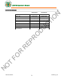
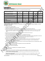
PERIODIC MAINTENANCE
Periodic maintenance should be performed at the following intervals:
Maintenance Operation Every Use
(daily)
Every 5 hrs
(daily)
Every 10 Hrs Every 25 Hrs Every 50 Hrs
Inspect for loose, worn or damaged parts
Clean debris bag
Check tire pressure
Engine (See Engine Manual)
Check for excessive vibration
Check belt
Grease zerks
DRIVE
Belts are normal replaceable wear items.
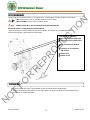
BELT REPLACEMENT
1. Follow steps 1-9 in the impeller removal section. The impeller will need to be removed to replace the belt
2. Loosen the set screws on the pulley at the end of the shaft. This will allow the pulley to slide out of the way of the belt.
Walk the old belt off the pulley.
3. Remove the old belt by feeding it through the housing and replace it with a new one, making sure to walk the belt around
the bottom pulley.
Continued next page
Grease: Wheels, Casters, and Shaft Bearings.
Tire air pressure: Check at regular intervals & maintain: Rear SP 13" tires at 20 psi. (137.9 kPa).
IMPELLER REMOVAL
1. Disconnect spark plug wire.
2. Secure the unit to keep it from moving.
3. Remove the nozzle (item 7) from the housing, then remove the plate it was attached to (item 30).
4. Walk the belt (item 22) off of the lower pulley (item 23) and then slide it off of the impeller groove. If you cannot walk it off of
the bottom pulley loosen the bearings (item 24) on the underside this will allow a little more play in the pulley.
5. Slide belt out of belt groove in impeller hub drive pulley.
6. Remove impeller bolt and lock washer.
7. If impeller slides off freely, proceed to (step 12). (Do not drop impeller).
8. If impeller does not slide off crankshaft, place two crowbars between impeller and housing on opposite sides. Pry impeller
away from engine until it loosens. A penetrating oil can help loosen a stuck impeller.
9. Slide impeller off of crank shaft and remove impeller from housing.
10. Reinstall new impeller, new impeller bolt and lock washer in reverse order of removal. (See the Parts Illustration on pages 10-
13 for parts break-down and Parts List on page 11 for proper impeller bolt torque specifications.)
11. When impeller is installed, slide the belt back into the groove on the hub and walk it back onto the bottom pulley. Retighten
the bearings if they were loosened.
12. Reattach nozzle plate and nozzle in reverse order of removal.
13. Reconnect spark plug wire.
14. Check for proper operation.
NOT FOR REPRODUCTION

QVSPEU Operator’s Manual
Part No 831507 831507_E_HI
9
4. Install the impeller and make sure the belt is in the groove on the hub. Use new hardware to attach the impeller. DO NOT
reuse old impeller bolts.
5. Align the pulley so the belt will be running straight, then tighten the set screws. NOTE: make sure the key is in the lower
pulley is still in place and hasn’t fallen out.
6. Reattach the nozzle plate and nozzle in reverse order of removal.
7. Reconnect spark plug wire.
8. Check for proper operation.
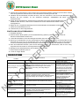
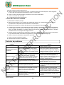
TROUBLESHOOTING
DRIVE CABLE ADJUSTMENT
1. Disconnect spark plug wire.
2. Remove the bag (item 5) and transmission cover (item 21) which will allow the transmission drive lever arms to be visible.
3. Loosen the two nuts on the barrel of the cable going into the drive levers.
4. Tension on the drive lever is reduced when the barrel of the cable is moved upwards towards the lever and tension is
increased when the barrel is removed further away from the lever. NOTE: Moving the barrel too much in either direction
will result in the drive lever constantly being engaged or not engaging at all.
5. When engaging the drive levers check the exposed transmission to make sure that the arms are properly engaging and
returning to a disengaged position.
6. Reattach the transmission cover and bag.
7. Reconnect spark plug wire.
8. Check for proper operation.
Problem Possible Cause Solution
Abnormal vibration Loose or out of balance impeller or loose engine.
Check impeller and replace if required.
Check engine.
Will not vacuum or has poor
vacuum performance
Dirty debris bag. Nozzle height set too high or low. Hose kit
cap missing. Clogged nozzle or exhaust. Excessive quantity of
debris.
Clean debris bag. Shake bag clean or
wash. Adjust nozzle height. Check for
hose kit cap. Unclog nozzle or exhaust.
Allow air to feed with debris.
Engine will not start
Stop switch off. Throttle in off position. Engine not in full choke
position. Out of gasoline. Bad or old gasoline. Sparkplug wire
disconnected. Dirty air cleaner. Low oil (honda only).
Check stop switches, throttle, choke
position and gasoline. Connect spark
plug wire. Clean or replace air filter. Or
contact a qualified service person.
Engine is locked, will not pull over Debris locked in impeller. Engine problem.
See page 6. Contact a engine service
dealer for engine problems.
Nozzle scrapes ground in lowest
height setting
Nozzle height out of adjustment.
Adjust nozzle height (See Nozzle height
fine adjustment for hard surfaces on page
6.
No self propelling
Transmission not in gear. Drive levers not engaging. Worn
out, broken, or mispositioned belt. Return springs on
transmission broken.
Check forward/reverse gear selection.
Check drive lever cable adjustment and
belt. Check return springs on
transmission.
Self propelled drive will not
release
Drive Levers adjusted too tight keeping the transmission
engaged.
Adjust the barrels on the drive levers to
decrease the tension on the
transmission.
NOT FOR REPRODUCTION

QVSPEU Operator’s Manual
Part No 831507 831507_E_HI
10
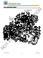
QVSPEU ENGINE PARTS DRAWING
119
116
44
45
49
45 113
112
96
TO THROTTLE
CONTROL
70
TO
CONTROL
LEVERS
1
2
43
9
20
21
22
23
24
48
26
27
25
35
39
40
41
42
43
45
44
46
47
68
49
50
51
54
52
53
93 49
41
49
62
44
58
63
45
56
65
66
60
14
45
91
64
64
64
105
104
110
111
109
114
59
45
44
NOT FOR REPRODUCTION

QVSPEU Operator’s Manual
Part No 831507 831507_E_HI
11
QVSPEU ENGINE PARTS LIST
ITEM DESCRIPTION
QV550HSP
PART NO.
QTY
QV900HSP
PART NO.
QTY
1ENGINE HONDA 5.5 OHV GX160 600115 1 - -
ENGINE 9 HP HONDA GX270UT2X QA2 - - 430701 1
2HOUSING WA W/LABELS 831600 1831600 1
3TRANSAXLE HYDRO GEAR 831218 1831218 1
4WHEEL 13" X 5" PNEU 831203 2831203 2
9ENGINE BASE WA 831105 1831107 1
14 CABLE SHIFTER CONTROL 831228 1831228 1
20
IMPELLER ASSY 5HP (torque 17-22 ft.lbs [23-30
N.m])
831607 1 - -
IMPELLER ASSY 9HP (torque 55-60 ft. lbs [75-81
N.m.])
- - 831121-S1
21 COVER TRANSAXLE WA 831114 1831114 1
22 BELT GATES 6822 831219 1 - -
BELT GATES 6824 - - 831280 1
23 PULLEY 3.25 X 3/4" BORE 610417 1610417 1
24 BEARING 3/4" CAST P BLOCK 350133 2350133 2
25 BRACKET MOUNT CONTROL CABLE 831113 1831113 1
26 COUPLER TRANSAXLE 831205 1831205 1
27 BRACKET ANTI ROTATION 831217 1831217 1
35 LABEL WARNING QV 831265 1831265 1
39 SCREWCAP 1/4"-20 X 2 1/4 HCS ZP 8041011 48041011 4
40 BOLT SHOULDER 1/4" X 1 1/2" 831255 2831255 2
41 NUT LOCK 1/4"-20 HEX ZP 8160001 48160001 4
42 KEY 3/16" SQ X 1" 9201078 29201078 2
43 SCREWCAP 5/16"-18 X 1 1/4" HCS ZP 8041029 48041029 4
44 WASHER 5/16" SAE 8172008 18 8172008 18
45 NUT LOCK 5/16"-18 HEX ZP 8160002 11 8160002 11
46 CABLE TRANS AXL E D RIVE 831309 2831309 2
47 SCREW SELF TAP 1/4"-20 X 5/8" HWH TYPE F 890359 4890359 4
48 SHAFT DRIVE 5HP QV 831206 1 - -
SHAFT DRIVE 9HP QV - - 831230 1
49 WASHER 5/16" FLAT 8171003 78171003 7
50 KEY 3/16" SQ X 2 1/4" 9201087 1 - -
KEY 1/4" SQ X 2 1/8 - - 9201122 1
51 SPRING RETURN 831210 2831210 2
52 WASHER LOCK 5/16" SPLIT 8177011 1 - -
WASHER LOCK 7/16" ST MED - - 8177013 1
53 SCREWCAP 5/16 -24 X 2 1/4" GR. 8 W/PATCH 831272 1 - -
SCREWCAP 7/16-20 X 2" GR. 8 ZP - - 500188 1
54 WASHER 1.125 OD X 0.344 ID X0.25 441150 1 - -
WASHER 1.5 OD X 0.45 ID X 0.5 THK - - 440176 1
56 SET SCREW 5/16"-18 X 5/16" 8084106 28084106 2
58 SCREWCAP 5/16"-18 X 1 3/4" HCS ZP 8041030 18041030 1
59 SCREWCAP 5/16-18 X 3/4 GR 5 HCS ZP 8041026 48041026 4
60 BRACKET RETURN SPRING MOUNT 831310 1831310 1
ITEM DESCRIPTION
QV550HSP
PART NO.
QTY
QV900HSP
PART NO.
QTY
62 SCREWCAP 5/16"-18 X 1 3/4" HCS ZP 8041031 18041031 1
63 CARRIAGE BOLT 1/4"-20 X 3/4" ZP 8024021 28024021 2
64 WASHER 1/4" SAE 8172007 88172007 8
65 BRACKET OFFSET SHIFT 831220 1831220 1
66 NUT LOCK 3/8"-16 HEX 8160003 18160003 1
68 SCREWCAP 5/16-18 X 3/4 HCS ZP 8041035 28041035 2
70 SCREWCAP 3/8"-16 X 1 1/4" HCS ZP 8041051 18041051 1
91 NUT 1/4"-28 HEX 8149001 18149001 1
93 SCREWCAP 5/16"-18 X 1 1/2" HCS ZP 8041030 4 - -
SCREWCAP 5/16"-18 X 1 3/4" HCS ZP - - 8041031 4
96 CABLE THROTTLE 440178 1440178 1
104 SCREWCAP 1/4"-20 X 3/4" W/PATCH 831263 1831263 1
105 WASHER .266 X .750 X .156 THK 831264 1831264 1
109 LABEL DANGER GUARD 900327 2900327 2
110 LABEL MADE IN USA 520116 1520116 1
111 LABEL PATENT PENDING 500183 1500183 1
112 BRACKET BRAKE QV 831295 1831295 1
113 BOLT SHOULDER 3/8" X 1/2" 830528 1830528 1
114 LINER QV 831283 1831283 1
116 BALL JOINT DETACHABLE 831615 1831615 1
119 BELT GUIDE QV 831302 1831303 1
NOT FOR REPRODUCTION

QVSPEU Operator’s Manual
Part No 831507 831507_E_HI
12
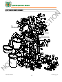
QVSPEU HOOD PARTS DRAWING
117
107
108
106
74 96
63
97 99
98
95
94
TO
ENGINE
66
90
100
TO
TRANSMISSION
14
5
6
7
8
2
9
11
12
13
18
10
15
16
17
19
69
73
28 29
30
31
32
79
34
36
37
38
45
49
58
59
49
61
44
45
45 49
66
67
68
62
45
49
74
62
75
77
76 77
75
49
45
82
45
49
85
59
87
45
88 89
49
45
70
81
76
86
52
TO
TRANSMISSION
49
72
80
67 3345
92
101 102
103
115
118
NOT FOR REPRODUCTION

QVSPEU Operator’s Manual
Part No 831507 831507_E_HI
13
QVSPEU HOOD PARTS LIST
ITEM DESCRIPTION
QV550HSP
PART NO.
QTY
QV900HSP
PART NO.
QTY
2HOUSING QV WA W/LABELS 831600 1831600 1
5QV BAG AND RING KIT - w/4 LATCH 831617 1831617 1
6HOOD QVSP W/LABELS 831603 1831603 1
7NOZZLE 32" 831606 1831606 1
8CASTER SWIVEL QV 831201 2831201 2
9ENGINE BASE 5 HP WA SP 831105 1 - -
ENGINE BASE 9 HP WA SP - - 831108 1
10 HANDLE LOWER LFT 831404 1831404 1
11 HOOD FILTER 831226 1831226 1
12 HOOD SCOOP QVSP W/LABEL 831602 1831602 1
13 ROD FILTER HOLDER QV 831266 1831266 1
14 SHIFTER CONTROL 831228 1831228 1
15 HANDLE LOWER RT 831403 1831403 1
16 HEIGHT ADJ ROD 831214 1831214 1
17 HEIGHT ADJ BRACKET WA 831110 1831110 1
18 HANDLE WISHBONE 831405 1831405 1
19 BRACKET HANDLE SUPPORT 831222 1831222 1
28 SPACER HANDLE 9 HP - - 831229 2
29 CAP 5 " VIN YL BLAC K 831211 1831211 1
30 PLATE NOZZLE WA QV 831109 1831109 1
31 HANDLE UPPER QV 831406 1831406 1
32 GRIP 1" OD X 9.5" 430342 2430342 2
33 ARM CLUTCH CONTROL QV WA 831116 2831116 2
34 BAG LATCH 840016 2840016 2
36 BUSHING FRAME PIVOT 831207 2831207 2
37 LABEL INSTRUCTION QV 831258 1831258 1
38 LABEL DRIVE DIRECTION 831270 1831270 1
44 WASHER 5/16" SAE 8172008 12 8172008 12
45 NUT LOCK 5/16"-18 HEX ZP 8160002 33 8160002 33
49 WASHER 5/16" FLAT 8171003 33 8171003 33
52 WASHER LOCK 5/16" SPLIT 8177011 28177011 2
58 NUT 5/16-18 SER HEX WSHR FLNG ZP 350346 6350346 6
59 SCREWCAP 5/16"-18 X 3/4" HCS ZP 8041026 48041026 4
61 SCREWCAP 5/16"-18 X 1" HCS ZP 8041028 68041028 6
62 SCREWCAP 5/16"-18 X 1 3/4" HCS ZP 8041031 12 8041031 12
63 SCREWCAP 1/4"-20 X 3/4" 8041004 28041004 2
66 NUT LOCK 3/8" -16 HEX 8160003 48160003 4
67 WASHER 3/8" FLAT 8171004 78171004 7
68 SCREWCAP 5/16"-18 2 3/4" HCS ZP 8041035 28041035 2
69 FRAME C ASTER QV WA 831108 1831108 1
70 SCREWCAP 3/8"-16 X 1 1/4" HCS ZP 8041051 28041051 2
72 STOP COLLAR 831216 1831216 1
73 PIVOT HEIGHT ADJ WA 831117 1831117 1
74 WASHER 2" OD X 0.344 ID X 16 GA 810652 8810652 8
75 NUT LOCK #10-24 HEX 8155007 88155007 8
76 SCREW MACH #10-24 X 3/4" 8059136 88059136 8
77 WASHER #10 SAE 8172005 12 8172005 12
79 CONTROL MOUNT HANDLE WA 831115 2831115 2
80 FILTER FRAME 831223 1831223 1
81 WASHER LOCK 3/8" ST MED 8177012 28177012 2
82 BOLT CARRIAGE 5/16"-18 X 3/4" ZP 8024039 48024039 4
85 SCREWCAP 3/4"-16 X 1" HCS ZP 8041050 28041050 2
86 KNOB 3/8" - 18 SOLID HUB 811230 1811230 1
87 BUSING HEIGHT ADJ BRKT QV 831215 1831215 1
88 PLUG TUBE INSERT 1" OD 890132 2890132 2
89 SCREWCAP 5/16"-20 X 1 1/2" 8041030 18041030 1
90 BOLT CARRIAGE 3/8" -16 X 1" 8024058 28024058 2
ITEM DESCRIPTION
QV550HSP
PART NO.
QTY
QV900HSP
PART NO.
QTY
92 SCREW PLASTITE 1/4"-20 X 3/4" HWH ZP 840082 1840082 1
94 CONTROL THROTTLE 440013 1440013 1
95 PLATE THROTTLE 500385 1500385 1
96 CABLE THROTTLE 440178 1440178 1
97 SCREW MACH HD PHIL #10-24 830514 2830514 2
98 NUT LOCK LT #10-24 8164005 28164005 2
99 NUT FLANGE 1/4"-20 900453 2900453 2
100 DUST SOCK DOUBLE LAYER QV 831282 1831282 1
101 PIN CLEVIS 0.25 X 0.50 440124 2440124 2
102 PIN CLIP HITCH .051 X 3/4" 440193 2440193 2
103 ARM CONTROL WA 440277 1440277 1
106 LABEL THROTTLE 810656 1810656 1
107 LABEL NOZZLE QV 831261 1831261 1
108 LABEL BADGING QV 831260 2831260 2
115 BAG QV NO CLASPS SERVICE 831613 1831613 1
117 DUST SKIRT 831268 1831268 1
118 GRIP CLUTCH CONTROL 440242 2440242 2
NOT FOR REPRODUCTION

QVSPEU Operator’s Manual
Part No 831507 831507_E_HI
14
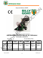
Manuel de l'Utilisateur QVSPEU
Image montrée avec accessoires optionnels
ASPIRATEUR QVSPEU Manuel de l'Utilisateur
QV550HSPEU, QV900HSPEU
Accessoires
Sacs de débris et Filtre
KIT TUYAU
D'ASPIRATEUR
JUPE DE SAC A
DEBRIS FREIN
DE RETENUE SAC A DEBRIS
STANDARD FILTRE DE
CAPOT
CHAUSSETTE
A
POUSSIERES
ET A DEBRIS
Tuyau souple de
5" (127mm) x 10'
(3m) pour passer
l'aspirateur dans
des endroits
difficiles à
atteindre
Dirige la poussière
loin de l'opérateur. Bloque les roues
arrière pour éviter
le roulage en roue
libre.
Standard sur les
modèles QV. Pour des
conditions
poussiéreuses.
Elimine les
poussières de
l'échappement
d'aspirateur par
filtrage.
Piège la
poussière et
l'éloigne de
l'opérateur.
N/P 831018 N/P 831268
N/P 831609
N/P 831613
N/P 831226
N/P 831282
POIGNEE
REGLABLE
Permet la
poignée pour
relever ou
abaisser pour
le confort.
N/P 831614
NOT FOR REPRODUCTION

QVSPEU Operator’s Manual
Part No 831507 831507_E_HI
15
CONTENU
CARACTERISTIQUES TECHNIQUES _______________________________________ 3
ETIQUETTES D'INSTRUCTION ____________________________________________ 4
LISTE DE CONTROLE D'EMBALLAGE ET ASSEMBLAGE _______________________ 5
FONCTIONNEMENT ET ENTRETIEN DE SAC _______________________________ 6-7
MAINTENANCE ET DÉPANNAGE _________________________________________ 8-9
PIÈCES ILLUSTRÉES ET LISTES DE PIÈCES _____________________________ 10-14
NOT FOR REPRODUCTION

QVSPEU Operator’s Manual
Part No 831507 831507_E_HI
16
CARACTÉRISTIQUES TECHNIQUES
QV550HSPEU QV900HSPEU
HP 5,5 (4,1 kW) 9,0 HP (6,6kW)
Moteur : Type GX160T1QX2 GX270K1QA2
Moteur : Capacité des réservoirs
carburant
3,88 pte (3,6 L) 6,3 pte (6,0L)
Moteur : Capacité en Huile 0,69 pte (0,65 L) 1,16 pte (1,1L)
Poids Total de l'Appareil : 226# (102,5 kg) 248# (112,5 kg)
Longueur Totale 63 po. (1,6m) 63 po. (1,6m)
Largeur Totale 33 po. (0,84m) 33 po. (0,84m)
Hauteur Totale
51 po. (1,3 m)
51 po. (1,3 m)
Pente de fonctionnement maxi.
200
200
NOT FOR REPRODUCTION

QVSPEU Operator’s Manual
Part No 831507 831507_E_HI
17
ETIQUETTES D'INSTRUCTION
Les étiquettes indiquées ci-dessous ont été installées sur votre Aspirateur QVSPEU de BILLY GOAT®. Si des étiquettes sont
endommagées ou manquantes, remplacez-les avant de faire fonctionner cet équipement. Les numéros d'articles de la Liste de
Pièces Illustrées et les numéros de pièces sont fournis pour faciliter la commande d'étiquettes de rechange. La position correcte
pour chaque étiquette peut être déterminée en se référant aux figures et aux numéros d'articles indiqués
ETIQUETTES MOTEUR
ETIQUETTE
AVERTISSEMENT
ARTICLE #35 N/P
831265
ETIQUETTE
PAPILLON DES GAZ
ARTICLE #106 N/P
810656
ETIQUETTE MISE EN GARDE
CONTRE DANGER ARTICLE
#106 N/P 900327
ETIQUETTE DIRECTION DE
CONDUITE ARTICLE #38 N/P
831270
INSTRUCTION LABEL
ITEM # 37 P/N 831258
NOT FOR REPRODUCTION

QVSPEU Operator’s Manual
Part No 831507 831507_E_HI
18
LISTE DE CONTROLE D'EMBALLAGE
Votre Aspirateur Billy Goat est expédié à partir de l'usine dans un carton, complètement assemblé, à l'exception de la buse.
Veuillez LIRE toutes les instructions de sécurité avant d'assembler l'appareil.
FAITES ATTENTION quand vous enlevez l'appareil de la boîte
METTEZ DE L'HUILE DANS LE MOTEUR AVANT DE DEMARRER
SAC DE PIECES & DOCUMENTATION D'ASSEMBLAGE
Carte de Garantie N/P - 400972, Manuel de l'Utilisateur N/P-831500, Déclaration de Conformité N/P-831503.
Manuel de Sécurité et de Mises en Garde Général N/P-100294
Liste de Contrôle de Pièces
Emballées
Sac à Débris N/P-831225
Chaussette à Poussières N/P-
831268
Buse Avant N/P-831606
Documentation d'Assemblage
N/P-831019
Honda 9 HP
Honda 5,5 HP
ASSEMBLAGE
1. Retirez l'appareil de la boîte. Soyez prudent car les câbles pourraient s'accrocher à quelque chose.
2. Attachez la buse avant (article 7) au logement et fixez-la avec les écrous freinés (article 58) situés dans le
sac de pièces
NOT FOR REPRODUCTION

QVSPEU Operator’s Manual
Part No 831507 831507_E_HI
19
FONCTIONNEMENT
FONCTIONNEMENT D'ASPIRATEUR
RÉGLAGE DE HAUTEUR DE BUSE D'ASPIRATEUR : Le réglage se fait en tournant le bouton dans le sens des aiguilles d'une
montre pour augmenter la hauteur et dans le sens inverse des aiguilles d'une montre pour la réduire. Réglez la hauteur de buse
en fonction des conditions de surface et de la taille des débris. Pour aspirer sur des surfaces planes, réglez la buse de 1/2 po.
(12,7 mm) à 5/8 po. (15,8 mm) au dessus du sol. Réglez plus haut pour un terrain et un gazon irréguliers.
POUR RAMASSAGE MAXIMUM: Réglez la buse près des débris, mais sans bloquer le flux d'air rentrant dans la buse. NOTA :
Ne plongez jamais la buse dans les débris.
DEBOUCHER UNE BUSE & UN ECHAPPEMENT BOUCHES : Eteignez le moteur et attendez que l'impulseur
s'arrête complètement et débranchez le fil de bougie. En portant des gants durables, retirez l'obstruction.
DANGER, l'obstruction peut contenir des objets tranchants. Rebranchez le fil de bougie.
SAC A DEBRIS
Les sacs à débris sont des articles d'usure normaux remplaçables.
NOTA : Videz souvent les débris pour éviter de surcharger le sac avec plus de poids que vous ne pouvez soulever. Utilisez
la jupe à poussières lorsque les débris seront aspirés dans des conditions poussiéreuses.
NE PLACEZ PAS le sac sur ou à proximité d'une surface chaude, comme le moteur. Faites tourner le moteur à mi-vitesse
pendant la première demi-heure pour conditionner le nouveau sac. Votre nouveau sac nécessite une période d'adaptation pour
conditionner les pores du matériau contre des obstructions prématurées. Toute la surface du sac sert de filtre, et doit être
capable de respirer pour avoir une bonne performance d'aspiration. Assurez-vous que le moteur s'est complètement arrêté
avant de retirer ou de vider le sac.
FILTRE DE CAPOT
Les filtres de CAPOT sont des articles d'usure normaux remplaçables. Le filtre de capot doit être utilisé uniquement dans des
conditions poussiéreuses et sèches. Le filtre NE DOIT PAS être mouillé. Nettoyez uniquement avec un petit peu d'air comprimé.
CHAUSSETTE A POUSSIERES
Les chaussettes à poussières sont des articles d'usure normaux remplaçables. Voir à la page suivante pour l'entretien de
chaussette à poussières.
Cet aspirateur est conçu pour ramasser des ordures, des matières organiques et d'autres débris similaires.
Cependant, de nombreux aspirateurs sont utilisés là où des poussières sont mélangées avec des ordures. Votre appareil peut
aspirer par intermittence dans des endroits poussiéreux. La poussière est la plus grande cause de performance affaiblie
d'aspiration. Toutefois, ces règles permettront à votre machine de maintenir sa capacité d'aspirer dans des conditions
poussiéreuses :
• Faites tourner le moteur du régime au ralenti à un quart de vitesse.
• Le sac de débris doit être nettoyé plus souvent. Un aspirateur avec un sac doux et propre aura des bonnes
performances de ramassage. Un aspirateur avec un sac sale et plein aura de mauvaises performances de ramassage.
S'il est sale, videz les débris et secouez vigoureusement le sac pour enlever les poussières. Le fait d'avoir un ou
plusieurs sacs de débris de rechange est une bonne façon de réduire les temps d'arrêt pendant que les sacs sales sont
nettoyés. NE LAISSEZ PAS de débris dans le sac pendant le stockage.
PROPULSION
D'abord, réglez le levier de marche avant ou de marche arrière dans la position souhaitée. (Le fait d'avoir le levier à la verticale mettra
l'appareil en position de point mort). Pour conduire en ligne droite appuyez sur les deux leviers, pour tourner à droite, appuyez
uniquement sur le levier de droite, et pour tourner à gauche, appuyez sur le levier de gauche. Quand vous n'appuyez sur aucun levier,
l'appareil roule en roue libre. N'embrayez pas partiellement la transmission quand vous embrayez les leviers. Les leviers doivent être
complètement embrayés. Une utilisation prolongée de l'embayage partiel pourrait provoquer des dommages internes à la transmission.
NOT FOR REPRODUCTION

QVSPEU Operator’s Manual
Part No 831507 831507_E_HI
20
SOINS ET ENTRETIEN DE CHAUSSETTE A POUSSIÈRES
Objet : La chaussette à poussière agit comme un filtre secondaire diminuant la quantité de poussières qui s'échappe du sac.
Les chaussettes à poussières doivent être UNIQUEMENT utilisées dans des conditions sèches et poussiéreuses. Le fait
d'utiliser la chaussette à poussières dans des conditions humides ou mouillées risque d'endommager la chaussette à poussières
et de diminuer l'efficacité du filtre.
La chaussette à poussières peut être installée par simple fixation de bandes Velcro d'accouplement entre le sac et la chaussette
à poussières. Au fil du temps, la chaussette à poussières commencera à se remplir de poussières pendant l'utilisation. Retirez
périodiquement la chaussette à poussières, videz la poussière lâche et nettoyez la chaussette. Pour un nettoyage léger, il suffit
de secouer la chaussette, et pour un nettoyage en profondeur, voir ci-dessous. Pour retirer la chaussette, il suffit de séparer la
bande Velcro.
Informations pour Soins de Chaussette à Poussières
NE COGNEZ PAS LE SAC CONTRE D'AUTRES OBJETS N'ACCROCHEZ LE SAC CONTRE RIEN
NETTOYEZ DELICATEMENT UNIQUEMENT AVEC DE L'AIR COMPRIME, DE L'EXTERIEUR.
GARDEZ LA BUSE A 6-12 POUCES DU TISSU.
Les chaussettes à poussières sont des articles d'usure normaux remplaçables. Pièce de Rechange N/P - 831282
NE MOUILLER RIEN
NOT FOR REPRODUCTION
Seite laden ...
Seite laden ...
Seite laden ...
Seite laden ...
Seite laden ...
Seite laden ...
Seite laden ...
Seite laden ...
Seite laden ...
Seite laden ...
Seite laden ...
Seite laden ...
Seite laden ...
Seite laden ...
Seite laden ...
Seite laden ...
Seite laden ...
Seite laden ...
Seite laden ...
Seite laden ...
-
 1
1
-
 2
2
-
 3
3
-
 4
4
-
 5
5
-
 6
6
-
 7
7
-
 8
8
-
 9
9
-
 10
10
-
 11
11
-
 12
12
-
 13
13
-
 14
14
-
 15
15
-
 16
16
-
 17
17
-
 18
18
-
 19
19
-
 20
20
-
 21
21
-
 22
22
-
 23
23
-
 24
24
-
 25
25
-
 26
26
-
 27
27
-
 28
28
-
 29
29
-
 30
30
-
 31
31
-
 32
32
-
 33
33
-
 34
34
-
 35
35
-
 36
36
-
 37
37
-
 38
38
-
 39
39
-
 40
40


Simplicity QVSPEU Benutzerhandbuch
- Kategorie
- Spielzeuge
- Typ
- Benutzerhandbuch