
Instruction manual
Gebruiksaanwijzing
Manuel d’utilisation
Bedienungsanleitung
Dampflokomotive BR 94

2
Das Vorbild
Mit der Reihe T 16 hatte die
Preußische Staatsbahn bereits 1905
eine leistungsfähige fünffach gekup-
pelte Tenderlok in Dienst gestellt
und mit dieser Konstruktion gute
Erfahrungen gemacht. Steigende
Zuglasten und der Wunsch nach
einem größeren Einsatzradius legten
eine Weiterentwicklung des Loktyps
nahe und man schuf die ab 1913
gelieferte T 16.1, spätere Baureihe
94.5. Einsatzgebiete der Maschinen
waren von Anfang an der schwere
Rangierdienst und der Streckendienst
auf Steilstrecken. In diesem Bereich
konnte die T 16.1 auf einigen Strecken
sogar den aufwendigen Zahnradbetrieb
ablösen. Durch die beiden Weltkriege
wurden die Loks in Europa ver-
streut und waren bei zahlreichen
Bahnverwaltungen im Einsatz. Die
Deutsche Reichsbahn musterte die
letzten Exemplare 1971 aus, bei der
Bundesbahn konnten sie sich noch drei
Jahre länger halten. Heute existieren
noch verschiedene Museumsloks, wobei
sich bei den Dampfbahnfreunden
mittlerer Rennsteig mit gleich vier
Maschinen ein Schwerpunkt befindet.
Das Modell
Der „Rennsteighirsch“ im eigenen
Garten? PIKO macht es möglich! Die
liebevolle Umsetzung der Baureihe
94.5 ist eine echte Bereicherung des
Fuhrparks in der Baugröße G. Neben
einer möglichst großen Vorbildtreue
standen bei der Konstruktion Aspekte
wie Robustheit und ein hoher Spielwert
im Fokus. Im Ergebnis ist ein Modell
entstanden, das nicht nur
den Herausforderungen des Freiland-
einsatzes über einen langen Zeitraum
gewachsen ist, sondern mit einem
werksseitig eingebauten Rauchsatz und
zahlreichen Lichtfunktionen aufwarten
kann. Eine Besonderheit ist hierbei eine
LED im Bereich des Stehkessels, die bei
Dunkelheit einen rötlichen Feuerschein
in den Führerstand zaubert – ganz wie
im Original. Das zweitgeteilte Fahrwerk
erlaubt das Befahren kleiner Radien
und sorgt gleichzeitig durch die ausge-
klügelte Achslagerung stehts für guten
Gleiskontakt.
Technik
• Zwei 7-pol., kugelgelagerte
Bühlermotore
• Vier kugelgelagerte Antriebsachsen
• Zwei Räder mit Haftreifen
• Stromabnahme über fünf
Edelstahlradsätze mittels Radkontakte
• Zusätzlich vier federnd gelagerte
Schleifkontakte direkt auf der Schiene
• Ein großes eingebautes Gewicht
• Beleuchtetes Spitzensignal mit der
Fahrtrichtung wechselnd
• Mit Dampf-Entwickler
• Digitalvariante inklusive
Digitaldecoder und Sound
• Digitalvariante inklusive Reed Kontakt
• Triebwerksbeleuchtung
• Standard-Bügelkupplung
• Länge: 492 mm
• Gewicht: ca. 3000 g
• Details
• Detailliertes Gehäuse
• Freistehende, einzeln angesetzte
Kesselleitungen
• Teile aus speziellem Kunststoff für den
Outdoor Gartenbetrieb
• Feine Nachbildung der Griffstangen
• Filigrane Speichenräder mit
Edelstahlradreifen
• Vorbildgerechte und komplette
Beschriftung
Technische Angaben
Nennspannung
Das Modell wird innerhalb eines
Spannungsbereiches von 0 bis 24 V
betrieben.
Stromversorgung
Die Lokomotive benötigt Trafos oder
Fahrregler, welche min. 2 A und
max. 5 A liefern. Verwenden Sie nur
zugelassene und einwandfrei arbeitende
Trafos und Fahrregler.
Antrieb
Das Modell besitzt zwei
durchzugskräftige 7-polige,
kugelgelagerte Bühlermotore, welche
über ein robustes Getriebe vier Achsen
antreiben.
Lieber PIKO Gartenbahn Freund
Wir freuen uns, dass Sie sich für eine
Spur G Lokomotive aus dem Hause
PIKO entschieden haben. Wie alle PIKO
Modelle, ist auch diese Lok von unseren
Mitarbeitern mit viel Liebe zum Detail
konstruiert, sorgfältig zusammengebaut
und während der Entwicklung intensiv
getestet worden, um Ihnen maximalen
Fahrspaß und viel Freude mit der Lok
zu garantieren.
Passend zu Ihrer Lok bieten wir eine
ganze Reihe von Wagen- und
Gebäudemodellen sowie attraktives
Zubehör für Ihre Gartenbahn-Anlage an.
Schauen Sie für weitere Informationen
einfach mal in unseren ausführlichen
PIKO G Katalog, in den PIKO Webshop
unter www.piko-shop.de oder beim
Fachhändler Ihres Vertrauens vorbei
und überzeugen Sie sich von unserem
umfangreichen Sortiment.
Sollten Sie Verbesserungsvorschläge
oder positive Kritik zu Ihren
PIKO Modellen haben, können Sie
uns Ihre Eindrücke per E-Mail an
hotline@piko.de,
per Fax +49 3675/8972-50
oder per Post an
PIKO Spielwaren GmbH,
Lutherstraße 30,
96515 Sonneberg/Thüringen mitteilen
oder die Sozialen Medien nutzen, um
mit uns in Kontakt zu treten.
Herzlichen Dank für Ihren Kauf und viel
Spaß mit Ihrer PIKO Spur G BR 94.
Ihr PIKO Team

3
Beleuchtung
Funktionsfähiges Spitzensignal mittels
LEDs, mit der Fahrtrichtung wechselnd.
Triebwerksbeleuchtung mittels
Funktionstaste oder Schalter schaltbar.
Empfehlungen
Entnahme des Modells
Entnehmen Sie das Modell bitte
vorsichtig aus der Styroporverpackung,
damit die Anbauteile wie Handstangen
usw. nicht beschädigt werden.
Erstbetrieb Ihrer Lok
Wir empfehlen, die Lok jeweils ca.
30min je Fahrtrichtung ohne Belastung
einfahren zu lassen, damit das Modell
einen optimalen Rundlauf und eine gute
Zugkraft erhält.
Bitte beachten Sie, dass der
einwandfreie Lauf der Lok nur mit
sauberen Schienen und Rädern
gewährleistet ist.
Minimaler Radius
Die Lok kann auf Gleisen mit einem
Radius von 600 mm (23.62‘’) fahren.
Aufgrund der Bauart empfiehlt sich
dennoch ein Mindestradius von 920
mm (36.28“).
Bitte beachten Sie, dass ein längerer
Betrieb auf Kurven mit kleineren Radien
zu einem stark erhöhten Verschleiß der
Lokomotive und der Schienen führt.
Geschwindigkeit der Lok
Durch die großen Räder besitzt die
BR 94 einen hohen Schwerpunkt und
kann so bei kleinen Radien und hohen
Geschwindigkeiten schnell entgleisen
oder umkippen. Wir empfehlen deshalb,
die Fahrweise der Lok dem Vorbild
entsprechend anzupassen.
Inbetriebnahme des Dampf-
Entwicklers
Benutzen Sie das PIKO Dampfdestillat.
Füllen Sie nur etwa 10 bis 20 Tropfen
davon in den Schornstein. Achtung!
Wenn zu viel Destillat eingefüllt
ist, arbeitet der Dampf-Entwickler
nicht! Überschüssiges Destillat durch
Umdrehen der Lok ausschütten. Das
Heizelement des Dampf-Entwicklers ist
sehr empfindlich, führen Sie deshalb auf
keinen Fall Fremdkörper in den Schlot
ein. Ein Fahren ohne Dampfdestillat
oder verbleibende Reste von Destillat
im Dampf-Entwickler schaden diesem
nicht.
Analoge Version
Digital Decoder
Das Modell ist werkseitig für den
Einsatz des PIKO SmartDecoder XP 5.1
G #36500 vorgerüstet. Nach dem
Einbau des Decoders kann die Lok auf
digitalen Anlagen eingesetzt werden.
Sounddecoder
Das Modell ist werksseitig für den
Einbau des PIKO SmartDecoder XP 5.1 S
G #36521 mit passendem Sound
vorbereitet. Der SmartDecoder XP 5.1 S
G #36521 wird mit einem
Breitbandlautsprecher mit wasserfester
Membrane geliefert
Digitale Soundversion
In der digitalen Soundversion sind
alle Funktionen bereits ab Werk
funktionstüchtig installiert.
#35268 Gleisschaltmagnet
In der Lok befindet sich ein
entsprechender Sensor (Reedkontakt),
der auf jeden Gleisschaltmagneten
#35268 reagiert und wahlweise Pfeife
oder Glocke auslöst.
Verschleißteile
Schienenschleifer und Radsatzkontakte
sind Verschleißteile! Diese sollten bei
Abnutzung getauscht werden!
Wartung/Pflege
Schmieren
Bitte geben Sie nach ca. 25 Betriebs-
stunden nach Lösen der Getriebeböden
jeweils eine kleine erbsengroße Menge
säurefreies und harzfreies Fett (PIKO
Schmierfett, Art.-Nr. 36216) auf die
Zahnräder. (siehe Schmierplan, Montage-
anleitung).
Alle beweglichen Teile z. B. Steuerung,
Kardanwelle, Radsätze sollten mit
Feinmechanikeröl vorsichtig abgeölt
werden.
Reinigen
Reinigen Sie die Lok nach längerem
Gartenaufenthalt mit einem milden
Reinigungsmittel und einem fusselfreien
Microfasertuch oder einem weichen
Pinsel.
Tauchen Sie auf keinen Fall die
komplette Lok zum Reinigen in eine
Lösung.
Achtung!
Bitte beachten Sie, dass bedingt
durch den Fahrbetrieb ein Abrieb
an den mechanischen Teilen (Räder,
Schleifer usw.) entstehen kann,
welcher Verunreinigungen auf
Teppichen oder anderen Materialien
entstehen lässt.
Austretendes Fett/Öl mit einem
Tuch abwischen. Bei Schäden
übernimmt die PIKO Spielwaren
GmbH keinerlei Haftung.
Achtung: Wichtige
Sicherheitshinweise
• Transformator regelmäßig auf
Schäden an Kabeln, Steckern,
Gehäuse und anderen Teilen
überprüfen!
• Bei einem Schaden darf der
Transformator bis zur vollständigen
Reparatur nicht mehr verwendet
werden!
• Lokomotive an nicht mehr als eine
Energiequelle anschließen!
• Kein Spielzeug. Nicht für Kinder unter
14 Jahren geeignet wegen funktions-
und modellbedingter scharfer Kanten
und Spitzen.
• Lokomotive nur mit einem
zugelassenen Transformator mit
Kennzeichnung betreiben!
• Der Transformator ist kein Spielzeug!
• Vor der Reinigung, die Lok vom
Transformator trennen!
• Drähte nicht in die Steckdose
einführen!

4
The Prototype
As early as 1905, powerful T 16 Class
0-10-0s were in service on the Prussian
State Railroads. Increasing tonnage and
the desire to use the T 16s in a larger
operating area led to the development
of the T 16.1 Class. The first T 16.1s,
later classified as the BR 94.5s, were
delivered in 1913. From the beginning
they were used in heavy switching
service and on steeply-graded routes.
The T 16.1 was even able to replace
rack locomotives on some steep grades.
Following two world wars, T 16.1s were
scattered across Europe and found
themselves working for various national
railroad administrations. The Deutsche
Reichsbahn retired their T 16.1 fleet in
1971, while the Deutsche Bundesbahn
kept theirs in service for another three
years. Today there are several T 16.1s
existing as museum locomotives, with a
noteworthy collection of four examples
owned by the Rennsteigbahn Steam
Train Association.
The Model
PIKO now makes it possible to have a
model of the famous “Rennsteighirsch”
train in your own backyard! Our new
BR 94.5 steam locomotive is a most
welcome addition to G scale. The
model is a fine example of prototype
fidelity married to robust design, which
guarantees plenty of play value. The
durable locomotive is tough enough
for the challenges of extended outdoor
operation and at the same time is
highlighted by sophisticated features
like a glowing red firebox and a
factory-installed smoke unit. The BR
94.5’s articulated chassis allows it
to operate over small radii and it’s
innovative axle bearings keep it’s
electrical wipers in good contact with
the rails.
Technical Details of the Model
• 2 powerful 7-pole motors, protected
from moisture
• 4 ball bearing drive axles gear-driven
• Two wheels with traction tires
• 5-wheelset electrical pickup with
internal contacts
• 4 spring-loaded pickup shoes sliding
directly on the rails
• Heavy weight for traction
• Directional LED headlight and rear
light
• Digital variant including digital
decoder and sound
• Digital variant including reed contact
• Engine lighting
• Smoke generator in smokestack
• Ready for installation of pulsed smoke
generators
• Length: 492 mm
• Weight: approx. 3000 g
Details
• Fine detailed loco body
• Detached, separate boiler pipes
• Smoke box door can be opened
• Delicate replica of hand rails
• Delicate spoke wheels with stainless
steel wheel rims
• Detailed cab interior with engineer
figure
• Constructed of special plastic for
outdoor use
• Authentic railroad decorations
Getting Started: Initial Operation
Unpacking the Model
Remove the styrofoam packaging
extremely carefully to prevent
damaging accessories and attached
parts such as handrails etc.
Initial Operation
We recommend letting the locomotive
run without a train for 30 minutes
in both directions, to properly break
it in. This will help achieve optimal
performance and longevity for the
locomotive. Of course, your model
should only be run on smooth and
perfectly clean tracks with reliable
electrical contact to all track
sections.
Dear PIKO garden railway
friend
We are pleased that you have chosen
a G scale locomotive from PIKO. Like
all PIKO models, this locomotive has
been designed by our employees with
great attention to detail, carefully
assembled and intensively tested
during development to guarantee you
maximum driving pleasure and a lot
of fun with the locomotive.
To match your locomotive, we offer a
whole range of car and building models
as well as attractive accessories for
your garden railway layout. For more
information, simply take a look at our
detailed PIKO G catalog, the PIKO web
shop at www.piko-shop.de, or visit your
local dealer and convince yourself of
our extensive range.
If you have any suggestions for
improvement or positive criticism about
your PIKO models, you can send us your
feedback by e-mail to hotline@piko.de,
by fax +49 3675/8972-50 or by mail to
PIKO Spielwaren GmbH,
Lutherstraße 30,
96515 Sonneberg/Thuringia, or use the
social networks to get in touch with us.
Thank you for your purchase and have
fun with your PIKO G scale BR 94.
Your PIKO Team

5
Smoke Unit Operation and Care
Drop about 10 to 20 drops of smoke
fluid into the top of the smokestack.
If over-filled, the smoke generator
will not work. Turn the loco upside
down to drain out excess smoke fluid.
Never insert any object down into the
smokestack. The heating element in the
center of the stack is delicate and easily
broken by foreign objects. Use only
PIKO smoke fluid to preserve the life of
the smoke generator. There is no harm
in leaving smoke fluid in the smoke
generator or in letting the the loco run
without fluid in the smoke generator.
Technical Data
Power Supply
The model should only be operated
on a pure, filtered DC power supply of
0 to 24 volts, with a capacity of 2 - 5
Amp and a fast-acting fuse or circuit
breaker to protect against short circuits.
Do not use a power supply which is not
in safe and perfect working condition.
(See “Digital Decoder” instruction for
operation on digital power.)
Drive System
The model contains 2 high capacity
motors, that are connected through
robust gearing to 4 axles.
Lighting
The model is equipped with an
automatic directional headlight, using
white LEDs for a realistic appearance.
The “front” lights are illuminated
according to the travel direction.
Precautions and Recommendations
Minimum Radius
The locomotive can run on tracks with
a radius of 600 mm (23.62“). Due to
the design a minimum radius of 920
mm (36.28“) is recommended. Natural-
ly, extended operation on small radius
curves leads to greatly increased wear
of the locomotive and track.
Analog version
Digital Decoder
The analog model
is prepared at
the factory for use with the PIKO
SmartDecoder XP 5.1 Art. No. #36500.
After plugging in the decoder, the
locomotive can be used on both digital
and analog layouts.
Sounddecoder
The analog model is factory prepared for
the installation of the PIKO SmartDecoder
XP 5.1 Sound #
36521
with original
sound. The PIKO SmartDecoder XP 5.1
Sound #
36521
comes with a full range
speaker with waterproof membrane. After
installation of the PIKO SmartDecoder XP
5.1, the locomotive can be used with all its
digital functions on digital layouts. When
used on analog layouts, only the driving
noise of the locomotive is reproduced.
Digital sound version
The digital sound version got all features
since leaving the factory.
#35268 Track switch magnet
In the locomotive there is a sensor (reed
contact),which reacts to every track
switching magnet #35268 and triggers
either whistle or bell.
Maintenance
Lubrication
After each 25 hours of operation, and
after any long periods of storage, please
lubricate the locomotive‘s gears with a
sparing amount of plastic-compatible,
non-hardening grease
(e. g. Lubricating
Grease PIKO no. # 36216)
.
Cleaning
If cleaning is necessary, use only a mild
cleaning agent (such as soap and water)
and gentle action with a soft non-
abrasive cloth or brush. Never immerse
the loco in liquid or “flood” any internal
parts!
Normal Wear Items
Electrical pick-up shoes, wheel wipers
and traction tires will wear with use and
should be replaced as needed.
Please Note! Damage to Carpets and
Other Surfaces: Normal operation
of the locomotive causes wear of
mechanical parts (wheels, electrical
pickups etc.). This produces carbonized
dust, grease and oil, which can
permanently stain carpets, wood
floors and other materials. It is the
user’s responsibility to take proper
precautions against this damage.
Wipe any grease or oil from the
track rails with a clean soft cloth.
PIKO Spielwaren GmbH, as well as
its representatives, distributors and
retailers, assume no liability for any
such damage.
Please Note!
Important Safety Precautions
• Check the power supply regularly
for any damage or problems.
• Do not use a malfunctioning or
damaged power supply!
• This model must only be operated
with one power source per circuit!
• This product is not a toy, not suitable
for personnel under 14 years of age.
This product has small parts, sharp
parts, and moving parts.
• This model must only be operated
with a safety-assured power supply
with the
identification!
• The power supply is not a toy!
• Disconnect the model from the
power supply before cleaning or
servicing!
• Do not insert the track power
connecting wires into household
“mains” voltage outlets.

6
MONTAGEANLEITUNG LOK
Service instructions · Manuel d’utilisation · Gebruiksaanwijzing
Schrauben / Screws / Vis / Schroeven
M 1:1
C E FA
E = 3,0 x 6
F = 2,2 x 4,5
A = 2,2 x 7
C = 3,0 x 10
onan
aus off

7
A
C
F
C
C
C
Haftreifenwechsel
Change the traction tyres
Remplacer bandages
Wisselen antislipbanden
C
C
C

8
%UFNHQVWHFNHU
-XPSHU
'HFRGHU
Entfernen Sie vorsichtig den Brückenstecker. Bitte nehmen Sie beide
Hände, um ein Verkanten/Verbiegen der Kontakte zu vermeiden. Stecken
Sie den Decoder auf die Trägerplatine. Durch seine Bauform lässt er sich
nur in korrekter Position aufstecken. Achten Sie bitte dennoch darauf, dass
die Kontakte nicht versetzt eingesteckt werden. Sollten Sie wieder auf
Analog umrüsten, gehen Sie in umgekehrter Weise vor. Achten Sie beim
Brückenstecker/Trägerplatine auf die Markierung (siehe Bilder).
Remove the jumper plug carefully. Please take
both hands to avoid tilting/bending of the contacts. Plug the decoder
onto the carrier board. Due to its design, it can only be attached in the
right position. However, please make sure that the contacts are not
moved sideways. If you switch back to analog, proceed in the opposite
way. Pay attention to the marking on the jumper plug/carrier board
(see pictures).
KABELANSCHLUSS-SCHEMA
Wiring scheme · Schema de câblage · Bedradingsschema
Feuerbüchse
fire box
grün / green
Orange / orange
rosa / pink

9
A
F
C
C
C
C
Fetten
Grease
Graisse
Smeren
Bitte verwenden Sie PIKO Schmierfett, Art.-Nr. 36216
Please use PIKO lubrication grease, no. 36216
Utiliser PIKO graisse, no. 36216
Gebruikt u s.v.p. het smeervet van PIKO, nr. 36216
Beim Zusammenbau auf die
korrekte Stellung der Räder achten!
Please pay attention to the correct
position of the wheels!
!
C
C
C
C

10
Decoder
Aux 8
Aux 7
Aux 6
Aux 5
Aux 4
Aux 3
Aux 2
Aux 1
+
Inp. 2
Rad r.
Rad l.
--
Inp. 1
+
Licht V
Licht H
Motor 2
Motor 1
Inp. 3
Soundmodul /
sound module
Lautstärke-
regler /
volume level
Soundmodul /
sound module
Decoder
Soundmodul /
sound module
rosa / pink
Feuerbüchse
fire box
grün / green
KABELANSCHLUSS-SCHEMA SOUND
Wiring scheme · Schema de câblage · Bedradingsschema

11
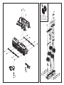
ANBAUTEILE
Fittings · Pièces de raccordement · Accessoireset

12
PIKO SmartDecoder
4.1 G
Sound G, Sounddecoder für Großbahnen
Anleitung zum Digitalbetrieb
HINWEIS: Die ausführliche
Bedienungsanleitung der PIKO
SmartDecoder 4.1 G finden Sie in
unserem Webshop als PDF auf der
Seite des jeweiligen Artikels. Dort
werden alle Möglichkeiten Ihres
neuen PIKO SmartDecoder 4.1 G
umfassend beschrieben.
1. Beschreibung
Dieser PIKO SmartDecoder 4.1 G ist
ein kompakter, sehr leistungsfähiger
Multiprotokolldecoder für Fahrzeuge
der Spurweite G. Er kann in DCC- und
Motorola- Digitalsystemen ver-
wendet werden und fährt ebenfalls
im Analogmodus mit Gleich- oder
Wechselspannung. Die jeweilige
Betriebsart wird automatisch erkannt.
Der lastgeregelte Decoder arbeitet
mit einer Frequenz von 18,75 kHz und
eignet sich dadurch für Gleichstrom-
und Glockenankermotoren bis zu einer
dauernden Stromaufnahme von 5 A.
Kurzzeitig höhere Motorströme werden
gut toleriert. Der PIKO SmartDecoder
4.1 G ist RailCom®, sowie RailCom
Plus® fähig und beherrscht sowohl
das ABCBremsen als auch die ABC-
Langsamfahrt.
Die Einstellung der Motorkennlinie
erfolgt über die minimale, mittle-
re und maximale Geschwindigkeit
(einfache Kennlinie), oder über die
erweiterte Fahrstufenkennlinie mit
Einzeleinstellungen für 28 Fahrstufen.
Der Decoder verfügt über
zwei fahrtrichtungsabhängige
Beleuchtungsausgänge, sowie über elf
zusätzliche Sonderfunktionsausgänge,
von denen drei mit Logikpegel
ausgeführt sind. Weiter stehen am
Decoder vier Servoanschlüsse für
Modellbauservos zur Verfügung.
Der Rangiergang mit gedehntem
Langsamfahrbereich und die drei mög-
lichen Anfahr-, Bremsverzögerungen
können über Funktionstasten geschaltet
werden. Ein großer Energiespeicher zum
unterbrechungsfreien Fahrgenuss rundet
die vielfältigen Möglichkeiten dieses
Decoders ab.
2. Einbau des PIKO SmartDecoder
4.1 G
Sie können den Decoder mit den
entsprechenden Schrauben wie im
„Anschlussschema Digital” gezeigt, in
Ihrem Fahrzeug befestigen.
Beachten Sie beim Einbau, dass Sie
mit den Schraubenköpfen keine Kabel
einklemmen oder beschädigen. Achten
Sie bei der Platzierung des Bausteins im
Fahrzeug darauf, dass nirgendwo eine
leitende Verbindung entsteht.
3. Anschluss des PIKO SmartDecoder
4.1 G
Bauen Sie den Decoder sorgfältig
nach den Anschlussplänen in dieser
Bedienungsanleitung in die Lok ein.
Überprüfen Sie den korrekten Einbau
mit einem Durchgangsprüfer oder
einem Ohmmeter. Stellen Sie sicher,
dass auch nach Schließen der Lok keine
Kurzschlüsse entstehen können und
keine Kabel eingeklemmt werden.
Der Decoder ist generell gegen
Kurzschlüsse oder Überlastung gesi-
chert. Werden jedoch beim Einbau
Kabel vertauscht oder Kabel verschie-
dener Funktionen (z.B. Radsatz und
Motor) kurzgeschlossen, kann diese
Sicherung nicht wirken und der Decoder
wird zerstört. Für Decoder, die durch
unsachgemäße Behandlung beschädigt
wurden, entfällt der Garantieanspruch.
Die erste Inbetriebnahme sollte auf
dem Programmiergleis bei aufgerufe-
nem Programmiermodus der Zentrale
erfolgen.
Beim Lesen oder Programmieren fließen
in der Regel sehr kleine Ströme, die den
Decoder im Falle eines Kurzschlusses
nicht beschädigen.
Ein Kurzschluss zerstört den Baustein und
eventuell die Elektronik der Lok!
Sonderfunktionen A1bisA8
Die Sonderfunktionsausgänge A1bisA8
des Decoders befinden sich auf der rech-
ten Schraubklemmleiste des Decoders
(Abbildung 1). Die dort anschließbaren
Verbraucher werden gemeinsam über die
Klemme U+ mit Spannung versorgt.
Detaillierte Informationen zu allen An-
schlüssen finden Sie in der ausführlichen
Bedienungsanleitung.
SUSI Schnittstelle
An die SUSI Schnittstelle des PIKO
SmartDecoder 4.1 G können entweder
ein PIKO Sound-Modul mit SUSI, oder
ein geeigneter Funktionsdecoder, ange-
schlossen werden.
Welche CV für die jeweilige Anwendung
zu programmieren ist, entnehmen Sie
bitte der ausführlichen Bedienungsan-
leitung.
In der Werkseinstellung gibt der De-
coder an der SUSI Schnittstelle Daten für
ein PIKO Sound-Modul aus.
4. Inbetriebnahme des Decoders
(Auslieferungszustand)
Am Steuergerät die Adresse 3 eingeben.
Der PIKO SmartDecoder 4.1 G fährt, je
nachdem mit welchem Datenformat er
angesprochen wurde, im DCC-Betrieb
mit 28 Fahrstufen oder im Motorola-Be-
trieb. Beim Einsatz einer RailCom Plus®
fähigen Digitalzentrale, oder bei einer
mfx®-fähigen Digitalzentrale meldet sich
der Decoder automatisch an und kann
sofort bedient werden. Wird der Decoder
auf konventionellen, analog betriebenen
Anlagen eingesetzt, so kann er mit
einem Gleich- oder Wechselstromfahr-
gerät gesteuert werden. Die Betriebsart
wird vom PIKO SmartDecoder 4.1 G
automatisch erkannt.

13
Märklin und mfx® sind eingetragene Warenzeichen der Gebr. Märklin & Cie. GmbH, Göppingen
Motorola ist ein eingetragenes Warenzeichen der Motorola Inc. Tempe-Phoenix (Arizona/USA)
RailCom® und RailCom Plus® sind eingetragene Warenzeichen der Lenz Elektronik GmbH
HINWEIS: Im Gleichspannungsbetrieb
wird Ihr Fahrzeug erst bei höherer Span-
nung (Fahrregler weiter aufgedreht)
anfahren, als Sie es eventuell im Betrieb
mit analogen Fahrzeugen gewohnt
waren.
Funktionsausgänge im Analogbetrieb
Es ist möglich, den Sounddecoder so
einzustellen, dass auch im Analogbetrieb
die Funktionstasten F0 - F12, so wie sie
im Function Mapping zugewiesen sind,
eingeschaltet sein können. Dazu müssen
zuvor mit einer Digitalzentrale die CVs
13 & 14 programmiert werden. Die ent-
sprechenden Werte können der CV-Ta-
belle der ausführlichen Bedienungsanlei-
tung entnommen werden. Ab Werk sind
die Lichtfunktion F0, das Motorgeräusch
F1, die Innenraumbeleuchtung F4 &
F5, die Führerpultbeleuchtungen F6 &
F7 und die Rücklichter (rot) F9 einge-
schaltet.
Motorola®
Um die Funktionen F1 - F16 bei Einsatz
mit Motorola-Zentralen erreichen zu
können, verfügt der Sounddecoder über
4 Motorola® Adressen. Die drei Folgead-
ressen für die Funktionen F5 - F16 sind
aufsteigend zur Decoderadresse und
können in der CV61 nach Bedarf durch
die Werte 1 (F5 - F8), 2 (F5 - F12), oder
3 (F5 - F16) aktiviert werden.
Konfigurations-CVs
Neben der Decoderadresse sind die
Betriebsarten- und Konfigurations-CVs
eines Lokdecoders sicherlich die wich-
tigsten CVs. Diese sind beim PIKO
SmartDecoder 4.1 G Sound die CVs 12
und 29. Eine Konfigurations- CV bein-
haltet im Regelfall verschiedene Grund-
einstellungen eines Decoders, wie zum
Beispiel die Fahrtrichtungsumkehrung.
Berechnungsbeispiele hierzu finden Sie
in der ausführlichen Bedienungsanlei-
tung.
RailCom®, RailCom Plus®
Im Sounddecoder kann in der CV29
RailCom® ein-, oder ausgeschaltet
werden. Ist in der CV28 RailCom Plus®
eingeschaltet, so meldet sich der
Sounddecoder an einer RailCom Plus®
fähigen Zentrale mit seinem Loksymbol,
Decodernamen und seinen Sonderfunk-
tionssymbolen automatisch an. Durch
diese RailCom Plus® Technik müssen
also keine Lokdaten in der Zentrale
hinterlegt und keine Lokadressen in den
Sounddecoder programmiert werden.
Bremsverhalten
Der Sounddecoder versteht folgende
Bremstechniken:
• Märklin® Bremsstrecke (Bremsen mit
analoger Gleichspannung)
• DCC-Bremsgenerator
• ABC-Bremsen
Weiter kann der Sounddecoder das Fahr-
zeug mit einem einstellbaren Bremsweg
Zielgenau anhalten.
Detaillierte Informationen zum Thema
„Bremsverhalten“ finden Sie in der aus-
führlichen Bedienungsanleitung.
Funktionsausgänge
Eine umfassende Darstellung aller
Möglichkeiten der Funktionsausgänge
finden Sie in der ausführlichen Bedie-
nungsanleitung.
Einfaches und erweitertes Function
Mapping
Im einfachen Function Mapping (CVs
33 - 46) können die Zuordnungen der
Schaltaufgaben wie Beleuchtung und
Sonderfunktionsausgänge den Funkti-
onstasten F0 bis F12 der Digitalzentrale
frei zugeordnet werden. Die abschaltba-
re Anfahr-, Bremsverzögerung und der
Rangiergang können in den CVs 156
und 157 beliebigen Funktionstasten
zugewiesen werden. Nähere Informa-
tionen finden Sie in der ausführlichen
Bedienungsanleitung.
Steuerung einer elektrischen Kupplung
Elektrische Kupplungen bestehen oft-
mals aus feinsten Kupferdrahtwicklun-
gen. Diese reagieren in der Regel emp-
findlich auf dauerhaften Stromfluss, weil
sie dadurch relativ heiß werden. Der
Sounddecoder kann bei entsprechenden
Einstellungen dafür sorgen, dass die
Funktionsausgänge A4 und A5 nach
einer einstellbaren Zeit selbstständig
abschalten, ohne dass dazu die Funkti-
onstaste ausgeschaltet werden muss.
Rangiertango, automatische Ent-
kupplungsfahrt
Ist die elektrische Kupplung aktiviert,
kann ein Rangiertango eingerichtet
werden.
Die Funktionsweise eines Rangiertangos:
1. Lok fährt mit einer einstellbaren
Geschwindigkeit für eine einstellbare
Zeit entgegen der momentanen Fahr-
trichtung (Andrücken)
2. Lok hält an und schaltet die Fahrtrich-
tung um
3. Entkupplungsvorgang, anschließend
entfernt sich die Lok für eine einstell-
bare Zeit vom entkuppelten Fahrzeug
(Abrücken)
4. Lok hält an, jetzt hat die Lok wieder
die ursprüngliche Fahrtrichtung.
Erweitertes Function Mapping
Durch die enorme Komplexität kann
das erweiterte Function Mapping nicht
sinnvoll über die Programmierung ein-
zelner CVs eingestellt werden. Sollten
Sie das erweiterte Function Mapping
verändern wollen, so benötigen Sie das
Test- und Programmiergerät PIKO Smart-
Programmer (#56415) und (optional)
den PIKO SmartTester (#56416). Weitere
Informationen zum erweiterten Function
Mapping entnehmen Sie bitte der aus-
führlichen Bedienungsanleitung.
Servosteuerung
Der Sounddecoder ermöglicht die direk-
te Ansteuerung von vier Servomotoren
über die Servosteckplätze der Trägerpla-
tine. Die Einstellmöglichkeiten der Hal-
tepositionen und der jeweiligen Verfahr-
geschwindigkeit entnehmen Sie bitte
der CV-Tabelle. Die Zuordnung zu den
Funktionstasten erfolgt ausschließlich
über das erweiterte Function Mapping.
Soundeinstellungen
Die Gesamtlautstärke kann über das im
Fahrzeugboden eingebaute Lautstär-
kepoti eingestellt werden. Die im vorde-
ren Drehgestell verbauten Reedkontakte

14
1 & 2 lösen beim Überfahren eines
entsprechend platzierten Gleismagneten
die Sounds Pfeife und Horn aus.
HINWEIS: Um einen PIKO Sound auf
den Sounddecoder aufzuspielen, benö-
tigen das Test- und Programmiergerät
PIKO SmartProgrammer (#56415)
und (optional) den PIKO SmartTester
(#56416).
Alle weiteren Informationen zum
Soundteil des PIKO SmartDecoder 4.1 G
Sound G sowie die verfügbaren Einstell-
möglichkeiten entnehmen Sie bitte der
ausführlichen Bedienungsanleitung.
Energiespeicher
Der auf dem Decoder verbaute Energie-
speicher kann über die CV-Programmie-
rung ein- oder ausgeschaltet werden.
Die Stützzeit ist in 500ms Schritten auf
bis zu 8 Sekunden einstellbar. Wird die
CV251 = 128 (Bit7 = 1) gesetzt, so ist
der Energiespeicher eingeschaltet und
die Stützzeit beträgt 500ms. Über die
Bits 0 - 3 kann nun die Stützzeit in der
genannten Schrittweite auf bis zu 8
Sekunden erhöht werden.
Rücksetzen auf Werkseinstellung
(Reset)
Um den Sounddecoder wieder in Werk-
seinstellung zu bringen, programmieren
Sie bitte die CV8 = 1.
Programmierung
Die Grundlage aller Einstellmöglichkei-
ten des Decoders bilden die Konfigu-
rations-Variablen (CVs). Der Decoder
kann mit der PIKO G-Digitalzentrale mit
Navigator oder anderen DCC-Zentralen,
sowie mit Motorola-Zentralen program-
miert werden.
Nähere Informationen zu den Program-
miermöglichkeiten entnehmen Sie bitte
der ausführlichen Bedienungsanleitung.
Zuordnung der Funktionstasten
F0 Licht F9 Sicherheitsventil F18 Ausschlacken
F1 Rauchgenerator F10 Führerstandstür F19 Sanden
F2 Pfeife lang F11 Führerstandsfenster F20 Schienenstöße
F3 Glocke F12 Zylinderdampf F21 Kurvenquietschen
F4 Fahrgeräusch F13 Injektor F22
Bremsgeräuch deakt.
F5 Führerstandsbeleuchtung F14 Kohle schaufeln F23 Speisepumpe
F6 Fahrwerksbeleuchtung F15 Pfeife kurz F24 Luftpumpe
F7 Rangiergang F16 Kuppeln
F8 Ton aus F17 Zugbremse

15
CV-Tabelle
CV Beschreibung Bereich Wert*
1 Adresse der Lok
DCC: 1 - 127
Motorola: 1 - 80
3
2 Minimale Geschwindigkeit (ändern, bis die Lok bei Fahrstufe 1 gerade fährt) 1 - 63 1
3Anfahrverzögerung
1 bedeutet, alle 5 ms wird die aktuelle interne Geschwindigkeit um 1 erhöht
Beträgt die interne maximale Geschwindigkeit z.B. 200 (CV 5 = 50 oder CV 94 = 200), dann beträgt die Anfahrzeit von 0 auf Vmax 1 Sekunde 0-255 25
4 Bremsverzögerung (Zeitfaktor wie CV 3) 0-255 6
5 Maximale Geschwindigkeit (muss größer als CV 2 sein) 1 - 63 45
6 Mittlere Geschwindigkeit (muss größer als CV 2 und kleiner als CV 5 sein) 1 - 63 13
7 Softwareversion (Der verwendete Prozessor kann upgedatet werden) - untersch.
8 Herstellerkennung Decoderreset, Werte wie in CV 59
verschieden
162
17
18 Lange Lokadresse
17 = Höherwertiges Byte
18 = Niederwertiges Byte
1 - 9999
192 - 231
0 - 255
2000
199
208
29
Konguration nach DCC-Norm
Bit 0=0 Normale Fahrtrichtung
Bit 0=1 Entgegengesetzte Fahrtrichtung
Bit 1=0 14 Fahrstufen
Bit 1=1 28 Fahrstufen
Bit 2=0 Nur Digitalbetrieb
Bit 2=1 Automatische Analog-/Digitalumschaltung
Bit 3=0 RailCom® ausgeschaltet
Bit 3=1 RailCom® eingeschaltet
Bit 4=0 Fahrstufenkennlinie aus CV 2, 5 und 6 benutzen
Bit 4=1 Fahrstufenkennlinie aus CV 67 - 94 benutzen
Bit 5=0 Kurze Adresse (CV 1)
Bit 5=1 Lange Adresse (CV 17/18)
0-63 14
30 Fehlerspeicher für Funktionsausgänge, Motor und Temperaturüberwachung
1 = Fehler Fkt.-Ausgänge, 2 = Fehler Motor, 4 = Temperaturüberschreitung 0-7 0
33-46 Einfaches Function Mapping
Zuordnung der Funktionsausgänge zu den CVs
CV 33 Lichtfunktionstaste (F0) bei Vorwärtsfahrt
CV 34 Lichtfunktionstaste (F0) bei Rückwärtsfahrt
CV 35 Funktionstaste F1
CV 36 Funktionstaste F2
CV 37 Funktionstaste F3
CV 38 Funktionstaste F4
CV 39 Funktionstaste F5
CV 40 Funktionstaste F6
CV 41 Funktionstaste F7
CV 42 Funktionstaste F8
CV 43 Funktionstaste F9
CV 44 Funktionstaste F10
CV 45 Funktionstaste F11
CV 46 Funktionstaste F12
Belegung der einzelnen Bits (bei CV100/101 Bit x = 0, Standard)
Bit 0 Lichtausgang vorn
Bit 1 Lichtausgang hinten
Bit 2 Funktionsausgang A1
Bit 3 Funktionsausgang A2
Bit 4 Funktionsausgang A3
Bit 5 Funktionsausgang A4
Bit 6 Rangiergang
Bit 7 Anfahr-/Bremsverzögerung
0-255
1
2
4
8
16
32
64
128
1
2
4
8
16
32
64
128
0
0
0
0
0
0
59
Reset auf die Werkseinstellung (auch über CV8 möglich)
1 = CV 0 - 256, sowie CV257 - 512 (RailCom® Bank 7)
2 = CV 257 - 512 (RailCom Plus® Banken 5 & 6)
3 = CV 257 - 512 (erweitertes Function Mapping Banken 1 & 2)
4 = CV 257 - 512 (PWM-Modulation Funktionsausgänge Banken 3 & 4)
0 - 4 0

16
PIKO SmartDecoder 4.1 G Sound G, Sounddecoder for G scale locomotives
Digital operation guide
NOTE: Detailed information on the
PIKO SmartDecoder 4.1 G is avail-
able as a PDF fi le on our Webshop
under the respective item number.
The file contains a full description of
all functions and operating possi-
bilities for the new SmartDecoder
4.1 G.
Description
The PIKO SmartDecoder 4.1 G decoder is
a powerful and compact multiprotocol
decoder for G scale locos, that can be
used with standard DCC, Selectrix, and
Motorola digital systems as well as in
DC or AC analog mode. It automatically
detects the operating system in use.
This load regulated decoder operates
on an 18.75 kHz frequency and are
designed for standard DC motors as
well as bell-shaped armature motors
(i.e. Faulhaber, Maxon, Escap) that draw
up to 1.2 A. Temporarily higher current
levels up to 2 A are easily tolerated.
The decoder is both RailCom® and
RailCom Plus®-ready and recognizes
ABC automatic stop sections and ABC
reduced speed sections.
The motor voltage can be controlled
either by a simple three-step motor
speed curve, with minimum, midpoint
and maximum voltage settings, or by
a user-loadable speed curve, with 28
individually-set speed steps.
The decoder provides two directional
lighting outputs, as well as seven ad-
ditional special function outputs. Slow-
speed switching mode, with extended
slow-speed range, along with three
accelleration and braking rates, can be
controlled via function keys.
Installing the PIKO SmartDecoder
4.1 G
The decoder may be mounted with the
screws provided.
Make sure that there is no short circuit
caused by the mounting screws. When
you install the decoder, make sure that
there are no conductive connections
anywhere inside the vehicle.
Connection of the PIKO SmartDe-
coder 4.1 G
Install the decoder carefully according
to the connection plan in this manual.
Use an ohmmeter to check whether the
installation is correct. Check for crossed
wires and short circuits before and after
reinstalling the shell.
The decoder is protected against shorts
and overload. However, if during the in-
stallation cables are reversed or if shorts
occur between functions (e.g. wheel set
and motor), the protection will not work
anymore and the decoder will be dam-
aged. We disclaim all responsibility and
guarantee in case of misuse or damage
of the decoder.
Place the model on your programming
track with programming mode activated
on your DCC system. During program-
ming or when reading the model’s DCC
address, a small amount of current will
fl ow through the model, which does
not affect the decoder; even in the event
of a short circuit.
Special functions A1 bis A8
The special function outputs A1 to A8
of the decoder are placed on the right
screw terminal of the decoder (Image
1). The power consumers connected
to this terminal will be provided with
current by the U+ terminal. You can find
detailed information about all connec-
tions in the detailed instruction manual.
A short circuit in the area of the
motor, lighting, pick-up wiper, or
wheelsets can destroy the decoder
and electronics of the model!
SUSI interface
At the SUSI interface of the PIKO Smart-
Decoder 4.1 G you can either use a PIKO
sound module with SUSI or a suitable
single-function decoder.
You can fi nd which CV should be
programmed for its respective function
output in the operating instructions.
The decoder is factory set to send data
to the PIKO sound module via the SUSI
interface.
First-time use of the decoder (state
of delivery)
Enter address 3 on your DCC control
system. Depending on your DCC
system‘s data format, the decoder will
operate using 28 speed steps or in
Motorola mode. When using a RailCom
Plus®-enabled DCC system or with an
mfx®-capable DCC system, the decoder
is recognized and can be operated
immediately. If the decoder is used on
a conventional analog layout, it can be
controlled with a DC or AC power pack.
The decoder will automatically detect
the layout’s operating mode.
Note: In DC analog mode, your model
will only start at a higher voltage than
what you may accustomed to when
operating analog models. You will need
to turn the throttle up for the model to
start operating.
Function outputs in analog mode
It is possible to set the sound decoder
so that the function keys F0 - F12, as
assigned in the function mapping, can
also be switched on in analog opera-
tion. To do this, CVs 13 & 14 must be
programmed beforehand with a digital
central unit. The corresponding values
can be taken from the CV table of the
detailed operating instructions. Ex works
the light function F0, the engine noise
F1, the interior lighting F4 & F5, the
driver‘s cab lights F6 & F7 and the tail
lights (red) F9 are switched on.
Motorola®
To be able to reach the functions F1 -
F16 when used with Motorola command
stations, the sound decoder has 4 Moto-
rola® addresses. The three following

17
addresses for the functions F5 - F16 are
ascending to the decoder address and
can be activated in CV61 as required by
the values 1 (F5 - F8), 2 (F5 - F12), or 3
(F5 - F16).
Configuration -CVs
Besides the decoder address, the ope-
rating mode and configuration CVs of
a locomotive decoder are certainly the
most important CVs. For the PIKO Smart-
Decoder 4.1 G Sound these are CVs 12
and 29. A configuration CV usually con-
tains various basic settings of a decoder,
such as direction reversal. Calculation
examples for this can be found in the
detailed operating instructions.
RailCom®, RailCom Plus®
In the sound decoder RailCom® can be
switched on or off in CV29. If RailCom
Plus® is switched on in CV28, the sound
decoder automatically logs on to a Rail-
Com Plus® capable command station
with its locomotive symbol, decoder
name and its special function symbols.
This RailCom Plus® technology means
that no locomotive data has to be
stored in the command station and no
locomotive addresses have to be pro-
grammed into the sound decoder.
mfx®
The PIKO SmartDecoder 4.1 G Sound
also supports the mfx® data format.
If the digital command station used is
mfx® capable, the sound decoder auto-
matically registers with its locomotive
symbol, decoder name and its special
function symbols. This mfx® technology
means that no locomotive data has to
be stored in the control center and no
locomotive addresses have to be pro-
grammed into the sound decoder.
Braking behavior
The sound decoder understands the fol-
lowing braking techniques:
• Märklin® braking distance (braking
with analog DC voltage)
• DCC brake generator
• ABC braking
Furthermore, the sound decoder can
stop the vehicle precisely with an
adjustable braking distance. Detailed
information on the subject of „braking
behavior“ can be found in the detailed
operating instructions. Function out-
puts A comprehensive description of
all possibilities of the function outputs
can be found in the detailed operating
instructions.
Function outputs
A comprehensive description of all
possibilities of the function outputs
can be found in the detailed operating
instructions.
Simple and extended function Map-
ping
In the simple function mapping (CVs 33
- 46) the assignments of the switching
tasks like lighting and special function
outputs can be freely assigned to the
function keys F0 to F12 of the digital
central unit. The switchable acceleration,
braking delay and the shunting gear can
be assigned to any function keys in CVs
156 and 157. More detailed information
can be found in the detailed operating
instructions.
Control of an electrical coupling
Electrical couplings often consist of
finest copper wire windings. These
usually react sensitively to continuous
current flow because they become rela-
tively hot as a result. With appropriate
settings, the sound decoder can ensure
that the function outputs A4 and A5
switch off automatically after an adjus-
table time, without having to switch off
the function key.
Shunting tango, automatic uncou-
pling travel
If the electric coupler is activated, a
shunting tango can be set up.
How a shunting tango works:
1. locomotive moves against the current
direction of travel at an adjustable
speed for an adjustable time (press-
on)
2. locomotive stops and switches the
direction of travel
3. uncoupling procedure, then the loco-
motive moves away from the uncou-
pled vehicle for an adjustable time
(disengaging)
4. locomotive stops, now the locomotive
has the original driving direction
again.
Extended Function Mapping
Due to the enormous complexity the
extended function mapping can not be
set sensibly by programming single CVs.
If you want to change the extended
function mapping, you need the test
and programming device PIKO Smart-
Programmer (#56415) and (optional) the
PIKO SmartTester (#56416). For more
information about the extended functi-
on mapping please refer to the detailed
operating instructions.

18
Servo control
The sound decoder allows direct control
of four servo motors via the servo slots
of the carrier board. Here the slots
Servo1 (top) and Servo 2 (bottom) are
occupied. Servo 1 controls the sing-
le-arm pantograph at the front and
servo 2 controls the scissor pantograph
at the rear. Please refer to the CV table
for the setting options of the stop posi-
tions and the respective travel speed.
The assignment to the function keys is
done exclusively via the extended func-
tion mapping.
Sound settings
The overall sound volume can be adjus-
ted via the volume potentiometer built
into the vehicle floor. The reed contacts
1 & 2 built into the front bogie trigger
the sounds whistle and horn when
passing a correspondingly placed track
magnet.
NOTE: To record a PIKO sound on the
sound decoder, you need the test and
programming device PIKO SmartPro-
grammer (#56415) and (optional) the
PIKO SmartTester (#56416).
For all further information about the
sound part of the PIKO SmartDecoder
XP 5.1 Sound G and the available set-
ting options, please refer to the detailed
operating instructions.
Energy storage
The energy storage built on the decoder
can be switched on or off via CV pro-
gramming. The backup time can be
set in 500ms steps up to 8 seconds.
If CV251 = 128 (Bit7 = 1) is set, the
energy storage is switched on and the
backup time is 500ms. Bits 0 - 3 can
now be used to increase the back-up
time in the above-mentioned increments
up to 8 seconds.
Reset to factory setting (Reset)
To reset the sound decoder to factory
settings, please program CV8 = 8.
Programming
The basis of all setting possibilities
of the decoder are the configuration
variables (CVs). The decoder can be pro-
grammed with the PIKO G digital com-
mand station with Navigator or other
DCC command stations, as well as with
Motorola command stations.
For more information about the pro-
gramming possibilities, please refer to
the detailed operating instructions.
Function assignments
F0 Light F9 Safety valve F18 Slagging
F1 Smoke generator F10 Driver's cab door F19 Sanding
F2 Whistle long F11 Cab window F20 Rail joints
F3 Bell F12 Cylinder steam F21 Curve squeal
F4 Driving sound F13 Injector F22
Brake smoke deact.
F5 Cab lighting F14 Coal shovel F23 Feed pump
F6 Running gear lighting F15 Whistle short F24 Air pump
F7 Shunting gear F16 Coupling
F8 Sound off F17 Train brake

19
CV-Table
CV Description Area Value*
1Locomotive address
DCC: 1 - 127
Motorola: 1 - 80
33
2Minimum speed (the speed from 0 until the locomotive is running at speed step 1) 1 - 63 1 1
3Acceleration delay
1 means every 5 milliseconds the actual motor speed is increased by 1. If the maximum motor speed is 200 (CV 5 = 50 or CV 94 = 200),
then the acceleration rate from 0 to maximum speed is 1 second 0-255 25 25
4Braking rate (time factor like CV 3) 0-255 6 6
5Maximum speed (must be greater than CV 2) 1 - 63 45 45
6Average speed (must be greater than CV 2 and less than CV 5) 1 - 63 13 13
7Software version (The processor can be updated) - differently 162
8Manufacturer identication decoder reset, values like CV 59
different
162 117
17
18 Long locomotive address
17 = higher value Byte
18 = lower value Byte
1 - 9999
192 - 231
0 - 255
2000
199
208
2000
199
208
29
DCC standard conguration
Bit 0=0 Normal direction of travel
Bit 0=1 Opposite direction of travel
Bit 1=0 14 Speed steps
Bit 1=1 28 Speed steps
Bit 2=0 DCC-only mode
Bit 2=1 Automatic analog/digital recognition
Bit 3=0 RailCom® turned off
Bit 3=1 RailCom® turned on
Bit 4=0 Speed steps over CV 2, 5, and 6
Bit 4=1 Use the characteristic curve from CV 67 - 94
Bit 5=0 Short address (CV1)
Bit 5=1 Long address (CV 17/18)
0-63 14 0
30 Error codes for function outputs, motor, and temperature monitoring:
1 = fault function outputs, 2 = fault motor, 4 = overheating 0-7 0
14
33-46
Easy function mapping
Assignment of function outputs to CVs
CV 33 Lighting function key (F0) when moving forward
CV 34 Light function key (F0) when in reverse
CV 35 Function key F1
CV 36 Function key F2
CV 37 Function key F3
CV 38 Function key F4
CV 39 Function key F5
CV 40 Function key F6
CV 41 Function key F7
CV 42 Function key F8
CV 43 Function key F9
CV 44 Function key F10
CV 45 Function key F11
CV 46 Function key F12
Assignment of individual bits (with CV100 / 101 bit x = 0, standard)
Bit 0 Front light output
Bit 1 Rear light output
Bit 2 Function output A1
Bit 3 Function output A2
Bit 4 Function output A3
Bit 5 Function output A4
Bit 6 Switching (Shunting)
Bit 7 Acceleration / deceleration
0-255
1
2
4
8
16
32
64
128
1
2
4
8
16
32
64
128
0
0
0
0
0
0
0
59
Resetting to factory settings (also possible via CV8)
1 = CV 0 - 256, as well as CV257 - 512 (RailCom® Bank 7)
2 = CV 257 - 512 (RailCom Plus® Banks 5 & 6)
3 = CV 257 - 512 (extended function mapping banks 1 & 2)
4 = CV 257 - 512 (modulation function outputs banks 3 & 4)
0 - 4 0 132

PIKO SERVICE
PIKO Spielwaren GmbH
Lutherstraße 30 · 96515 Sonneberg, Germany
Fax: +49 36 75 89 72 50
e-mail: [email protected]
www.piko.de
©PIKO 2022/37250-90-7000
Belgien
PIKO Spielwaren GmbH
Robert Deneef
Latemstraat 20
B9840 De Pinte
Tel.: 0032 475 211790
e-mail: [email protected]
www.piko.de
China
DongGuan AMR Hobby &
Art Distribution Ltd.
Xintang Road, ChaoLang
Industrial Estate, ChaShan Town
523392 DongGuan City/ P.R. China
Tel.: 0769-81866863
Fax: 0769-81866861
e-mail: info@piko.cn
www.piko.cn
Dänemark
PIKO Spielwaren GmbH
Lutherstraße 30
D - 96515 Sonneberg, Germany
Tel.: +49 3675 89 72 42
Fax: +49 3675 89 72 50
e-mail: hotline@piko.de
www.piko.de
Frankreich / Luxemburg
T2M SAS
Techniques Modernes du Mode-
lisme
BP 30006 - Zone Industrielle
F- 57381 Faulquemont Cedex
Tel.: 0033-387292520
Fax: 0033387943722
e-mail: [email protected]
www.t2m-train.fr
Großbritannien
Gaugemaster Controls Ltd.
Gaugemaster House, Ford Road
GB - Arundel, West Sussex BN18
OBN
Tel.: 01903 - 884321
Fax: 01903 - 884377
e-mail: sales@gaugemaster.co.uk
www.gaugemaster.com/piko
Hong Kong
PIKO Asia Ltd.
Flat 5, 5/F, Lemmi Centre
50 Hoi Yuen Road
HK-Kwun Tong, Kowloon
Tel.: 00852-24408622
Fax: 00852-24400410
e-mail: info@pikoasia.com
www.piko.de
Italien
EMMEMODELS SRL /
PIKO Spielwaren GmbH
Via Brianza 10
I - 20843 VERANO BRIANZA MB
Tel.: 0039 0362 90 65 40
e-mail: info@emmemodels.it
www.emmemodels.it
www.piko.de
Mexiko
CORPORATIVO VIVE
S.A. de C.V. / Thiers 176 Esq.
Leibnitz. Col. Anzurez
Mexico D.F. 11590
Tel.: 055-52509215
Fax: 055-43340173
e-mail: contacto@corporativovive.
com
www.vivemodelismo.com
Niederlande
Scaletrading/PIKO Spielwaren
GmbH
Gabriël Metsustraat 10
NL - 7312 PS Apeldoorn
Tel.: +31-6-22993404 (GSM)
Fax: +31-55-8438549
e-mail: [email protected]
www.scaletrading.nl / www.piko.de
Österreich
PIKO Spielwaren GmbH
Lutherstraße 30
D - 96515 Sonneberg, Germany
Tel.: +49 3675 89 72 42
Fax: +49 3675 89 72 50
e-mail: hotline@piko.de
www.piko.de
Polen
PIKO Polska Sp. z o.o.
ul. Poziomkowa 19B2
81-589 Gdynia
Mobil: +48 500 366 553
e-mail: info@piko-polska.pl
www.piko-polska.pl
Rumänien
Minimodel Teh SRL
Calea Grivitei Nr 204A
RO - 010755 Bucuresti
Tel.: 021 - 2241273
Fax: 021 - 318167258
e-mail:[email protected]
Russland
OOO “PIKO RUS”
Dmitrovskoe shossee 100, B 2
127247 Moscow/ Russia
Tel.: 007-977 994 24 10
e-mail: info@piko-rus.com
www.piko-rus.com
Russland
Joint Stock Company “ST”
Svobody Str. 35, office 20
125362, Moskau
Tel.: +7 495-973-18-60
Tel.: +7 495-798-67-10
e-mail: [email protected]
www.pikorussia.ru
www.TrainModels.ru
Schweiz
ARWICO AG
Brühlstrasse 10
CH - 4107 Ettingen
Tel.: 061 - 722 12 22
e-mail: verkauf@arwico.ch
www.arwico.ch
Spanien
Trenes Aguilo
Vía Augusta 7
E - 08950 Esplugues de Llobregat
Tel.: 00 - 34 - 93 - 499 05 29
e-mail:
www.trenes-aguilo.com
Tschechien
NEXES INTERNATIONAL
Osadní 12a
CZ - 170 00 Praha 7
Tel.: 00420 233 372 482
e-mail: [email protected]
www.pikomodely.cz
Türkei
UGUR AKMAN - HOBBYTIME
Turan Günes Bulvari
Hilal Mah. 716 Sokak N° 5/A
TR - Cankaya - Ankara
Tel.: 0312 - 438 4031
Fax: 0312 - 438 0381
e-mail: akman@hobbytime.com.tr
www.hobbytime.com.tr
Ungarn
Modell & Hobby Kft.
Lehel u. 62
H - 1135 Budapest
Tel.: 01 - 2370743
Fax: 01 - 2370744
e-mail: v[email protected]
www.modell.hu
USA & Kanada
PIKO America LLC
4610 Alvarado Canyon Rd., Suite 5
San Diego CA 92120
Tel.: 619 - 280-2800
Toll-Free 1-877-678-4449
Fax: 619 - 280-2843
e-mail: support@piko-america.com
www.piko-america.com
0-24 V
-
 1
1
-
 2
2
-
 3
3
-
 4
4
-
 5
5
-
 6
6
-
 7
7
-
 8
8
-
 9
9
-
 10
10
-
 11
11
-
 12
12
-
 13
13
-
 14
14
-
 15
15
-
 16
16
-
 17
17
-
 18
18
-
 19
19
-
 20
20


