Whirlpool AKR 909 IX Program Chart
- Kategorie
- Dunstabzugshauben
- Typ
- Program Chart

AKR 909
5019 100 75101
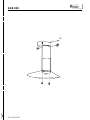
INSTALLATIONSANGABEN
Mindestabstand zur Kochfläche: 65 cm (Elektroplatten), 75 cm (Gas-, Öl-, Kohlekochplatten).
Die Dunstabzugshaube ist mit Befestigungsdübeln ausgestattet, die für die meisten Decken geeignet sind.
Trotzdem ist es erforderlich eine Fachkraft zu befragen, um sicherzustellen, daß die Materialien für die
jeweiligen Deckenqualität geeignet sind.
DAS GERÄT NICHT WÄHREND DER INSTALLATION AN DIE STROMVERSORGUNG
ANSCHLIESSEN.
INSTALLATION SHEET
Minimum height above cooker: 65 cm (electric cookers), 75 cm (gas, gas oil or coal cookers).
Expansion plugs are provided to secure the hood to most types of ceilings.
A qualified technician is needed, however, to make sure that the plugs are suitable to your ceiling.
DO NOT CONNECT THE APPLIANCE TO THE ELECTRICAL POWER SUPPLY DURING
INSTALLATION.
FICHE D'INSTALLATION
Distance minimale par rapport à la cuisinière : 65 cm (cuisinière électrique), 75 cm (cuisinière à
gaz, mazout ou charbon).
La hotte est munie de chevilles de fixation adaptées à la plupart des plafonds.
Il est cependant nécessaire de s'adresser à un technicien qualifié afin de s'assurer que le matériel est
approprié au type de plafond.
NE BRANCHEZ PAS L’APPAREIL AU RÉSEAU ÉLECTRIQUE PENDANT L’INSTALLATION.
INSTALLATIESCHEMA
Min. afstand van het kooktoestel: 65 cm (elektrische kooktoestellen), 75 cm (kooktoestellen op
gas, olie of kolen).
De wasemkap is voorzien van bevestigingspluggen die geschikt zijn voor de meeste plafonds.
Er moet echter contact opgenomen wroden met een gekwalificeerd technicus, om u ervan te
vergewissen dat de materialen geschikt voor het type plafond.
SLUIT HET APPARAAT NIET AAN OP HET ELEKTRICITEITSNET TIJDENS DE INSTALLATIE.
FICHA DE INSTALACIÓN
Distancia mínima de los quemadores: 65 cm (quemadores eléctricos), 75 cm (quemadores a gas,
gasóleo o carbón).
La campana está dotada de tacos de fijación adecuados a la mayor parte de los techos.
De cualquier modo, conviene consultar a un técnico cualificado para tener la certeza de que los
materiales son adecuados a su techo.
NO CONECTAR EL APARATO A LA RED ELÉCTRICA DURANTE LA INSTALACIÓN.
FICHA DE INSTALAÇÃO
Distância mínima do fogão: 65 cm. (fogões eléctricos), 75 cm. (fogões a gás, óleo ou carbono).
O exaustor é fornecido com parafusos de fixação adequados à maior parte dos tectos.
Contudo, é necessário chamar um técnico qualificado para verificar se os materiais são adequados ao
tipo de tecto.
DURANTE A OPERAÇÃO DE INSTALAÇÃO, NÃO LIGUE O APARELHO À CORRENTE
ELÉCTRICA.
SCHEDA INSTALLAZIONE
Distanza minima dai fuochi: 65 cm (fuochi elettrici), 75 cm (fuochi a gas, gasolio o carbone).
La cappa è dotata di tasselli di fissaggio adatti alla maggior parte dei soffitti.
È tuttavia necessario interpellare un tecnico qualificato per accertarVi sull’idoneità dei materiali a seconda
del tipo di soffitto.
NON CONNETTERE L’APPARECCHIO ALLA RETE ELETTRICA DURANTE L’INSTALLAZIONE.
ù(ùü+ù$ùþ
ü$12.)12.1.)2"012 0" FP02!"0120" FP0120".0! # 02!0. #
0! #.
. !! 32!."0.03 /.1 "0 *0"120!&1".20".2 #"0!11)20! #"2* #"
! 3+
.!)..#20...!.22 ..0##02010.0! 20$2+120.0.&020.2
.2.)22.2&#+. .02 2* 2" ! 3"
þûüüüþüþþüÿûÿùùþûÿùüÿùþ
ü+ùùùþ
D
GB
F
NL
E
P
I
GR

5019 100 75101
AKR 909
Zeichenerklärung
C:
Luftauslaß.
- Dunstabzugsversion
A
. nach rechts,
nach links oder in Richtung Wand.
- Umluftversion
F
nach rechts oder
links stellen.
A+D:
nur für Hauben in der
Dunstabzugsversion.
F:
nur für Hauben in der Umluftversion.
G-H:
An den vorgesehenen Stellen
einzusetzende Kabelschutzgummis.
Key
C:
air outlet.
- Extractor Version
A
. towards the right,
the left or the wall.
- Filter version
F
position it to the right
or the left.
A+D:
only for extractor version.
F:
only for filter version.
G-H:
Rubber cable grommets to install in the
appropriate positions.
Légende
C:
sortie de l'air.
- Version aspirante
A
. vers la droite,
vers la gauche ou vers la paroi.
- Version filtrante
F
: positionnez-la
vers la droite ou vers la gauche.
A+D :
uniquement pour la version aspirante.
F:
uniquement pour la version filtrante.
G-H :
Protections pour câbles en caoutchouc,
à installer dans les logements prévus à
cet effet.
Legenda
C:
luchtuitgang.
- Afzuigversie
A
. naar rechts, links of
naar de wand.
- Filterversie
F
plaats hem naar rechts
of naar links.
A+D:
alleen voor de Afzuigversie.
F:
alleen voor de Filterversie.
G-H:
Rubbertjes voor bescherming van de
kabel, aan te brengen op de daarvoor
bestemde plaatsen.
Leyenda
C:
salida de aire.
- Modelo Aspirador
A
. hacia la
derecha, la izquierda o la pared.
- Modelo Filtrante
F
posicionarla hacia
la derecha o la izquierda.
A+D:
sólo para el Modelo Aspirador.
F:
sólo para el Modelo Filtrante.
G-H:
Tapones de protección de los cables
que se han de introducir en las
correspondientes sedes.
Legenda
C:
saída de ar.
-Versão Aspirante
A
. para a direita,
esquerda ou para a parede.
-Versão Filtrante
F
vire-a para a direita
ou para a esquerda.
A+D:
apenas para a Versão Aspirante.
F:
apenas para a Versão Filtrante.
G-H:
Borrachas de protecção dos cabos para
introduzir nas respectivas sedes.
Legenda
C:
uscita dell’aria.
- Versione Aspirante
A
. verso destra,
sinistra o verso la parete.
- Versione Filtrante
F
posizionarla
verso destra o verso sinistra.
A+D:
solo per Versione Aspirante.
F:
solo per Versione Filtrante.
G-H:
Gommini proteggi cavi da inserire nelle
apposite sedi.
02.
&
/ "2 #.!.
2 ..!!)31"
$
! "2.
/02..!120!2 2 $
2 32!.!1.2 "
)
2 021202 ! "2./0! "
2..!120!
$'
) . 2 ..!!)31"
)
) . 2 32!.!1.2 "
*+
.12$.! 12.1..&/&.
2 2112"0/" /!0"
D
GB
F
NL
E
P
I
GR

AKR 909
5019 100 75101
1
2
2
3
4
4
5
5
5
5
5
5
C
F
6
7
7
7
7
7
7
A
A
D
H
G
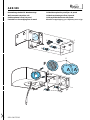
Dunstabzugseinheit für Wandmontage
Wall mounted extraction unit
Unité aspirante à fixer à la paroi
Eenheid voor bevestiging aan de wand
Unidad de aspiración para fijar a la pared
Unidade aspirante para fixar à parede
Unità aspirante da fissare alla parete
/...!!)31".120!&112 2 $

5019 100 75101
AKR 909
9
10
10
11
12
13
13
14
14
15
14
L
16
17
15
15
17a
17b
8
Wird nicht mitgeliefert, als
Einzelteil käuflich
Not provided, to be ordered
separately
Non fourni, à acheter à part
Niet geleverd, dient apart te
worden aangeschaft
No suministrado, debe
comprarse aparte
Não fornecido, deve ser
adquirido em separado
Non fornito, da acquistare a parte
û0$ !02. . !120 2
$&!12
Zuerst den Erdungsstecker (17a - gelb/grün) und dann den Hauptstecker (17b) anschließen
Connect the earth wires (17a - yellow/green) before inserting the main connector (17b)
Branchez les connecteurs de la prise de terre (17a - jaune/vert) avant de brancher le connecteur
principal (17b)
Sluit de aardingsstekkers (17a - geel/groen) aan alvorens de hoofdstekker (17b) aan te sluiten
Conectar los conectores de tierra (17a - amarillo/verde) antes de conectar el conector principal (17b)
Ligue os fios de ligação à terra (17a - amarelo/verde) antes de ligar o fio principal (17b)
Collegare i connettori della terra (17a - giallo/verde) prima di collegare il connettore principale (17b)
#/1202 #".& *"2"0&1"D2! !1 !1#/10202 02!)
1#/02!.E

AKR 909
5019 100 75101
19
19
18
20

AKR 909
5019 100 75101
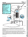
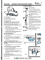
1.
Control panel.
2.
Grease filters.
3.
Grease filter release knobs.
4.
Lighting unit (halogen bulb).
5.
Telescopic flue.
6.
Extraction unit.
CLEANING THE GREASE FILTER
Wash the grease filter once a month, or
whenever the grease filter saturation indicator
flashes (Extraction speed indicator
2
).
1.
Unplug the appliance or switch off the mains
power supply.
2.
Remove the grease filters (
Fig. 1
):
a
- unscrew the grease filter knobs
b
- rotate downwards and remove the grease
filters from one side.
3.
After washing the metal grease filter, remount
in reverse order, making sure the entire
extraction surface is covered.
REPLACING BULBS
1.
Unplug the appliance or switch off the mains
power supply.
2.
Remove the grease filters (
a, b - Fig. 1
).
3.
Unscrew the lighting unit (
c - Fig. 2
).
4.
Remove the burnt-out bulb (
d - Fig. 2
) and fit
a new one.
Use only halogen bulbs 20W max.
5.
Screw the lighting unit back in place.
FITTING OR RENEWING THE CARBON
FILTER
1.
Unplug the appliance or switch off the mains
power supply.
2.
Remove the grease filters (
a, b - Fig. 1
).
3.
Mount the carbon filter, fixing it with the
screws supplied (
e - Fig. 3
).
4.
If the carbon filter needs renewing, remove the
old filter and fit a new one.
Change the carbon filter once a year and,
in any event, when the carbon filter
saturation indicator flashes (Extraction speed
indicator
3
).
5.
Refit the grease filters.
Resetting filter indicator:
press the extraction
OFF button (
9
) until the LED
2
and/or the LED
3
stops flashing.
CONTROL PANEL
1.
Light ON button.
2.
Light OFF button.
3.
Timer intensive speed button:
the hood operates at this speed
for 5 minutes and then returns to
the previous settings.
This function can be cancelled by
pressing button
8
or
9
.
4. Intensive
extraction speed
indicator.
5.
Extraction speed indicator
3
and
carbon filter saturation indicator
(when flashing).
This indicator is usually
deactivated: to activate it, press
buttons
3
and
8
simultaneously
until the indicator starts flashing;
repeat the operation to deactivate
the signal.
6.
Extraction speed indicator
2
and
grease filter saturation indicator
(when flashing).
7.
Extraction speed indicator
1
.
8.
Extraction ON speed increase
button -
1
Ö
3
Ö
1...
9.
Extraction OFF button.
1
2
5
2
6
3
3
4
4
Fig. 2
Fig. 3
c
d
e
e
Fig. 1
a
b
PRODUCT DESCRIPTION SHEET
F NL E PGBD GRI
-
 1
1
-
 2
2
-
 3
3
-
 4
4
-
 5
5
-
 6
6


Whirlpool AKR 909 IX Program Chart
- Kategorie
- Dunstabzugshauben
- Typ
- Program Chart
in anderen Sprachen
- English: Whirlpool AKR 909 IX
- français: Whirlpool AKR 909 IX
- español: Whirlpool AKR 909 IX
- italiano: Whirlpool AKR 909 IX
- Nederlands: Whirlpool AKR 909 IX
- português: Whirlpool AKR 909 IX
Verwandte Artikel
-
Whirlpool AKR 909 IX Program Chart
-
-
-
-
-
-
-
-
Whirlpool AKR 446 WH Program Chart
-
Whirlpool AKR 908 IX Program Chart