
GG
GG
BB
BB
((
((
22
22
--
--
22
22
00
00
))
))
DD
DD
EE
EE
((
((
22
22
11
11
--
--
33
33
99
99
))
))
FF
FF
RR
RR
((
((
44
44
00
00
--
--
55
55
88
88
))
))
EE
EE
SS
SS
((
((
55
55
99
99
--
--
77
77
77
77
))
))
WS 440 HF
Oper
ator’s manual Bedienungsanweisung
Manuel d’utilisation Manual de instrucciones
Please r
ead the operator’s manual carefully and make sure you understand the instructions before using the machine.
Lesen Sie die Bedien
ungsanweisung sorgfältig durch und machenSie sich mit dem Inhalt vertraut, bevor Sie das Gerät benutzen.
Lir
e attentivement et bien assimiler le manuel d’utilisation avantd’utiliser la machine.
Lea detenidamente el manual de instrucciones y asegúrese deentender su contenido antes de utilizar la máquina.

2
–
English
KEY
T
O SYMBOLS
Symbols on the mac
hine:
W
ARNING! The machine can be a
dangerous tool if used incorrectly or
carelessly, which can cause serious or
fatal injury to the operator or others.
Please read the operator’s manual
carefully and make sure you understand
the instructions before using the machine.
Always wear:
• Approved protective helmet
• Approved hearing protection
• Protective goggles or a visor
• Breathing mask
This product is in accordance with
applicable EC directives.
En
vironmental marking.
Symbols on the
product or its packaging indicate that this
product cannot be handled as domestic
waste. It must instead be submitted to an
appropriate recycling station for the recovery
of electrical and electronic equipment.
By ensuring that this product is taken care of
correctly, you can help to counteract the
potential negative impact on the environment and people that
can otherwise result through the incorrect waste
management of this product.
For more detailed information about recycling this product,
contact your municipality, your domestic waste service or the
shop from where you purchased the product.
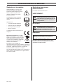
Explanation of warning le
vels
The w
arnings are graded in three levels.
W
ARNING!
IMPORTANT!
CAUTION!
Other symbols/decals on the mac
hine refer to special
certification requirements for certain markets.
!
W
ARNING! Used if there is a risk of serious
injury or death for the operator or damage to
the surroundings if the instructions in the
manual are not followed.
!
IMPOR
TANT! Used if there is a risk of injury
to the operator or damage to the
surroundings if the instructions in the
manual are not followed.
CA
UTION! Used if there is a risk of damage to materials or
the machine if the instructions in the manual are not
followed.

English
–
3
CONTENTS
Contents
KEY
TO SYMBOLS
Symbols on the machine:
.............................................. 2
Explanation of warning levels ....................................... 2
CONTENTS
Contents
....................................................................... 3
PRESENT
ATION
Dear Customer
, ............................................................. 4
Design and features ...................................................... 4
WS 440 HF ................................................................... 4
WHA
T IS WHAT?
What is what on the w
all saw? ...................................... 6
MA
CHINE´S SAFETY EQUIPMENT
Gener
al ......................................................................... 7
ASSEMBLING AND ADJUSTMENTS
Mount w
all mountings and rail ...................................... 8
Mount the saw carriage and saw .................................. 8
Fit the blade .................................................................. 9
Flush cutting ................................................................. 9
Fit the blade guard ........................................................ 10
Connect the power pack ............................................... 10
Adjusting the blade guard guide ................................... 11
Adjusting the locking handle on the blade guard guide 11
Adjusting the guide wheels ........................................... 11
Adjust the saw carriage ................................................ 12
OPERA
TING
Protectiv
e equipment .................................................... 13
General safety precautions ........................................... 13
Work safety ................................................................... 14
Basic working techniques ............................................. 15
ST
ARTING AND STOPPING
Bef
ore starting .............................................................. 16
Starting ......................................................................... 16
Stopping ........................................................................ 16
Dismantling the saw ...................................................... 16
Cleaning ........................................................................ 16
MAINTENANCE
Ser
vice .......................................................................... 17
Maintenance ................................................................. 17
Daily maintenance ........................................................ 17
TECHNICAL D
ATA
WS 440 HF
................................................................... 18
EC Declaration of Conformity ....................................... 20

4
–
English
PRESENT
A
TION
Dear Customer
,
Thank y
ou for choosing a Husqvarna product!
It is our wish that you will be satisfied with your product and
that it will be your companion for a long time. A purchase of
one of our products gives you access to professional help with
repairs and services. If the retailer who sells your machine is
not one of our authorised dealers, ask him for the address of
your nearest service workshop.
This operator’s manual is a valuable document. Make sure it
is always at hand at the work place. By following its content
(using, service, maintenance etc.) the life span and the
second-hand value of the machine can be extended. If you
will sell this machine, make sure that the buyer will get the
operator´s manual.
More than 300 y
ears of innovation
Husqv
arna AB is a Swedish company based on a tradition
that dates back to 1689, when the Swedish King Charles XI
ordered the construction of a factory for production of
muskets. At that time, the foundation was already laid for the
engineering skills behind the development of some of the
world's leading products in areas such as hunting weapons,
bicycles, motorcycles, domestic appliances, sewing
machines and outdoor products.
Husqvarna is the global leader in outdoor power products for
forestry, park maintenance and lawn and garden care, as well
as cutting equipment and diamond tools for the construction
and stone industries.
Owner responsibility
It is the o
wner’s/employer’s responsibility that the operator
has sufficient knowledge about how to use the machine
safely. Supervisors and operators must have read and
understood the Operator’s Manual. They must be aware of:
• The machine’s safety instructions.
• The machine’s range of applications and limitations.
• How the machine is to be used and maintained.
National legislation could regulate the use of this machine.
Find out what legislation is applicable in the place where you
work before you start using the machine.
The man
ufacturer’s reservation
All inf
ormation and all data in the Operator’s Manual were
applicable at the time the Operator’s Manual was sent to print.
Subsequent to publishing this manual Husqvarna may issue
additional information for safe operation of this product. It is
the owner’s obligation to keep up with the safest methods of
operation.
Husqvarna AB has a policy of continuous product
development and therefore reserves the right to modify the
design and appearance of products without prior notice.
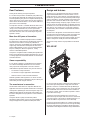
Design and f
eatures
The
WS 220 is a rail mounted wall saw which is used with
segmented diamond blades to cut hard materials such as
reinforced concrete, stone and brick. During development of
the WS 220, great focus has been placed on product weight
and user-friendliness, in order to improve and streamline the
operator’s work environment. With its low weight, compact
design and powerful high-frequency engine, the WS 220 is a
wall saw which can handle most jobs. Designed for 600-900
mm blades, this saw is able to cut through wall thicknesses of
up to 390 mm. The sawing system is stored on a compact
transport trolley, which facilitates transportation to and from
the workplace.
The Wall Saw is designed to cut hard materials like concrete
or reinforcement and should not be used for any purpose not
described in this manual. Safe operation of this product
requires the operator to read this manual carefully. Ask your
dealer or Husqvarna should you need more information.
Some of the unique features of your product are described
below.
WS 440 HF
It is our wish that y
ou will be satisfied with your product and
that it will be your companion for a long time. Think of this
operator
′
s manual as a valuable document. By following its
content (usage, service, maintenance, etc), the life span and
the second-hand value of the machine can be extended. If
you sell this machine, make sure that the operator
′
s manual
is passed on to the buyer.
A purchase of one of our products gives you access to
professional help with repairs and services. If the retailer who
sells your machine is not one of our authorised dealers, ask
him for the address of your nearest service workshop.
Husqvarna Construction Products has a policy of continuous
product development. Husqvarna reserves the right to modify
the design and appearance of products without prior notice
and without further obligation introduce design modifications.

English
–
5
PRESENT
A
TION
General
•
The powerful, water-cooled electric motor produces an
impressive 13 kW to the spindle, even though the saw
weighs just 25 kg (55 lbs).
• Spindle speed is electronically controlled and adjusted
using the remote control for the power unit.
• Short distance between blade and track, for a straighter
cut.
• Slip clutch for all movable components.
• The blade's direction of rotation can be controlled with the
remote control which allows one to choose the direction of
the water spray.
• Equipped with automatic blade brake that stops the blade
within a few seconds.
Complete sa
w equipment consists of:
•
One saw
• One track 1.2 m + saw carriage
• One track 2 m + saw carriage
• Four wall mountings
• One track holder
• One connector
• One blade guard 800 or one blade guard 1000
• One blade guard guide
• One tool kit
• One bottle of Husqvarna oil 220
• Transport cases for the different units.
• Cleaning brush
• Screws for flush cutting.
The saw carriage is mounted on both the long and short rails
at the factory to make cutting as easy as possible.
As a large part of the sawing work consists transporting, the
saw equipment is supplied in specially produced cases. The
cases provide good protection during transport and reduced
the number of packages that need to be moved between the
workplaces, which makes the work more effective.

6
–
English
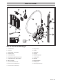
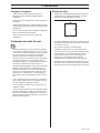
WHA
T IS
WHA
T?
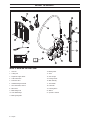
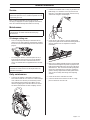
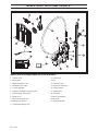
What is what on the wall sa
w?
1
Saw unit
2 Cutting arm
3 Propulsion engine, blade
4 Cable connection
5 Protective cover
6 Handle/blade guard mount
7 Hose connection, water in
8 Water hose
9 Blade flange hub
10 Outer blade flange
11 Blade guard guide
12 Blade guards
13 Track
14 Saw carriage
15 Locking handle
16 Wall mounting
17 Track holder
18 Connector
19 Cleaning brush
20 Tool kit
21 Operator
′
s manual

English
–
7
MA
CHINE´S SAFETY EQ
UIPMENT
General
This section descr
ibes the machine
′
s safety equipment, its
purpose, and how checks and maintenance should be carried
out to ensure that it operates correctly. See the ”What is
what?” section to locate where this equipment is positioned
on your machine.
Blade guar
ds
The b
lade guard must always be used when sawing. Make
sure the blade guard is in working order and that the outer
sections can be locked in place. Also check that the blade
guard guide is adjusted correctly and that the locking
mechanism in the blade guard guide for the saw is in working
order (see the adjusting the blade guard guide section).
Check that the blade is not in contact with the guard but is
centred in the blade guard.
Loc
king handle
Mak
e sure the locking handle on the saw carriage is correctly
adjusted (see the adjust the saw carriage section) so that the
saw unit sits securely on the carriage. Check that the locking
pin can be fully inserted in the hole on the handle when in the
locked position.
End stop on the rail
Mak
e sure that end stops are mounted on the ends of the rails
so that the saw does not come off the rails.
P
ower pack
Mak
e sure to check the safety equipment on the supplied
power unit. See the power unit manual.
!
W
ARNING! Never use a machine that has
faulty safety equipment! Safety equipment
must be inspected and maintained. See
instructions under the heading Checking,
maintaining and servicing the machine’s
safety equipment. If your machine does not
pass all the checks, take it to a service
workshop for repair.

8
–
English
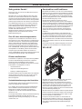
ASSEMBLING AND ADJUSTMENTS
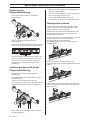
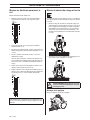
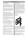
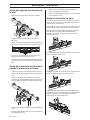
Mount wall mountings and rail
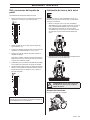
Fit the w
all mounting as set out below:
1 Mark off the cutting line and mark off the expander bolts
holes 165 mm (6.5") from the cutting line.
2 Drill 15 mm (5/8”) holes for the M12 (1/2”) expander bolts.
3 Hang the wall mountings loosely from the expander bolts,
using M6S 12 x 70 (1/2”x2”) or similar.
4 Place the rail in the wall mountings and tighten the
compression washers.
For vertical cuts, the rail must be mounted with the saw
carriage lock handle upwards. This to facilitate fitting the
saw unit.
5 Check that the rail is properly aligned with the tracks on
the wall mounts before tightening the screws.
6 Adjust the distance between the cutting line and the wall
mounting. The distance between the edge and the inner
face of the saw cut should be 89 mm (3.5"). Tighten the
expander bolts.
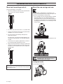
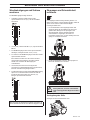
Mount the sa
w carriage and saw
The sa
w carriage is mounted on the rail at delivery. The
carriage can be dismounted from the rail by removing the end
stop on the rail and pulling the carriage away.
1 Fit the saw body in the saw carriage by lifting the saw body
into position. When the saw is lifted into position, the
locking handle moves up into an intermediate position. In
this position the saw remains in the saw carriage without
it needing to be held. However, it is not sufficiently secured
to begin cutting.
2 To secure the saw, lift the locking handle towards the saw
until the handle locks.
Loc
king the handle
Loc
k the handle using the pin.
IMPORTANT! Only use the connectors supplied when
purchasing the saw as older connectors are not designed
for the WS 400 series.
!
W
ARNING! To cut without the saw securely
assembled in the saw carriage and rail is
associated with mortal danger.

English
–
9
ASSEMBLING AND ADJUSTMENTS
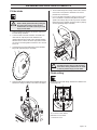
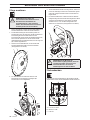
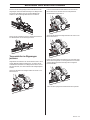
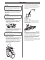
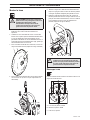
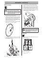
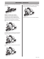
Fit the blade
1 Start by removing any dirt from the contact surfaces on
the blade flange and blade.
2 Check the blade’s direction of rotation. The blade shall
rotate with the exposed part of the diamond in the
rotational direction of the blade. Since the blade rotation
direction can be selected, the water spray from the blade
can also be selected regardless of how the saw is turned
on the rail.
3 Screw together the outer blade flange, blade and blade
flange hub (tightening torque 70-80 Nm).
4 Hang the blade with the blade flange and blade flange hub
fitted on the cutting arm (blade is not shown in the figure).
5 Turn the blade flange hub carefully so that it slides into one
of the tracks in the pivot arm and lands in the correct
position to be screwed fast.
6 Press in the blade shaft into the cutting arm at the same
time as the blade is rotated carefully. When the blade
spindle can no longer be pressed in by hand it should be
tightened using the supplied 18-spanner until it is properly
secured (tightening torque 70-80 Nm).
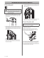
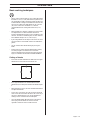
Flush cutting
Screw off the outer blade flange and mount the blade on the
blade flange hub.
A=110 mm/4.33 inch, 6xM10
B=89 mm/3.5 inch, 6xM8
C=144 mm/5.7 inch
!
WARNING! Never mount or dismount the
blade or blade guard without first pulling out
the power cable running to the saw unit.
Carelessness can result in serious personal
injury or even death.
!
WARNING! Exercise care when assembling
the blade so that it does not risk becoming
loose when cutting. Carelessness can result
in serious personal injury or even death.

10 – English
ASSEMBLING AND ADJUSTMENTS
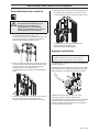
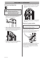
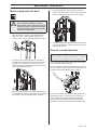
Fit the blade guard
1 Slip in the blade guard guide between the stays on the
blade guard. Place the blade guard guide in the middle.
Lock the plastic heel on the handle to the upper stay on
the blade guard.
2 Make sure that the cutting arm is positioned vertically. Lift
the blade guard over the blade and hang the guard in the
blade guard holder on the saw. Exercise care so that the
runners on the blade guard are positioned in the slots on
the water block.
3 Lock the blade guard by pulling the handle out of the
guard and then down towards the saw unit so that the
latch locks the handle.
4 To remove the guard, release the latch and pull the handle
upwards and inwards to the guard. Lock the plastic heel
on the upper stay.
5 Connect the water hose from the out-coupling on the saw
motor to the in-coupling on the blade flange hub.
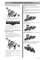
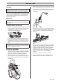
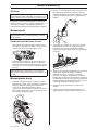
Connect the power pack
Read through the manual supplied with the power pack before
starting to use the machine.
When the saw unit, the blade and the blade guard are
mounted, the power cable (A) and the water cooling (B)
should be connected to the power pack.
Once the power cable is connected to the saw, the carabiner
on the cable must be attached to the saw unit to prevent
pressure on the plug when in operation. The carabiner must
be fastened to one of the bracket eyes on the handle which is
screwed to the back of the drive motor.
!
WARNING! Never mount or dismount the
blade or blade guard without first pulling out
the power cable running to the saw unit.
Carelessness can result in serious personal
injury or even death.
IMPORTANT! This machine is only intended for use
together with the Husqvarna PP 440 HF and PP 480 HF
power units. All other use is forbidden.

English – 11
ASSEMBLING AND ADJUSTMENTS
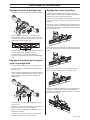
Adjusting the blade guard guide
• Loosen the nuts on the two adjustable guide wheels.
• Fit the blade guard guide to the blade guard.
• Turn the eccentric cam shafts with a 22 mm spanner until
the guide wheels touch the rail.
• Hold the shaft in position with a 22 mm spanner and
tighten the nut with a 16 mm spanner.
• Make sure the wheels turn easily and that there is no play
in the blade guard guide.
Adjusting the locking handle on the
blade guard guide
• Fit the blade guard guide to the saw unit.
• Loosen the two stop screws with a 3 mm allen key.
• Adjust the locking handle by turning the eccentric cam
shaft with a screwdriver until the locking handle tightens
around the blade guard bracket.
• Tighten the two stop screws with a 3 mm allen key.
• Remove the 4 screws that hold the snap-in lock in position
with a 4 mm Allen key.
• Adjust the snap-in lock. The snap-in lock must tighten
around the top rail.
• Tighten the 4 screws that hold the snap-in lock in place
with a 4 mm Allen key.
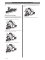
Adjusting the guide wheels
In order for the saw to run stably and saw a straight cut, the
four guide wheels must rest against the rail and not have too
much play.
Check the guide wheels before each cut. When there is too
much play between the saw carriage and rail the guide wheels
must be adjusted:
Loosen the two hexagon socket M10 screws with an 8 mm
allen key. Also loosen the two stop screws which locks the two
exentiric guide wheels with an 3 mm allen key.
Turn the shafts gently with a 16mm wrench until the guide
wheels rest agains the rail.
Hold the 16 mm wrench in position and tighten the two stop
screws with a 3 mm allen key.
Press down the locking device and pull the saw carriage in
both directions by hand. Carriage should slide easily with a
slightly resistance. All 4 guide wheel should spin.

12 – English
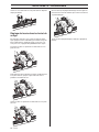
ASSEMBLING AND ADJUSTMENTS
Tighten screws with a 8 mm allen key. Repeat the previous
step.
Adjust the saw carriage
As the saw wears, after a number of hours working, it can be
a good idea to ensure that the saw sits firmly in the saw
carriage and rail. If not, the handle probably needs adjusting:
Loosen the two stop screws with a 3 mm allen key.
Turn the two excenter sleeves with a 8 mm allen key until the
shaft is tight and parallell to the saw unit.
Tighten the two stop screws with a 3 mm allen key.
Make sure the locking handle is properly adjusted by open
and close and see that the spring loaded lock is in locked
position.
Then secure the locked handle with the locking pin.

English – 13
OPERATING
Protective equipment
General
Do not use the machine unless you are able to call for help in
the event of an accident.
Personal protective equipment
You must use approved personal protective equipment
whenever you use the machine. Personal protective
equipment cannot eliminate the risk of injury but it will reduce
the degree of injury if an accident does happen. Ask your
dealer for help in choosing the right equipment.
Always wear:
• Approved protective helmet
• Hearing protection
• Protective goggles or a visor
• Breathing mask
• Heavy-duty, firm grip gloves.
• Tight-fitting, heavy-duty and comfortable clothing that
permits full freedom of movement.
• Boots with steel toe-caps and non-slip sole.
Be careful as clothing, long hair, and jewellery can get caught
in moving parts.
Other protective equipment
• Fire fighting equipment
• Always have a first aid kit nearby.
General safety precautions
This section describes basic safety directions for using the
machine. This information is never a substitute for
professional skills and experience. If you get into a situation
where you feel unsafe, stop and seek expert advice. Contact
your dealer, service agent or an experienced user. Do not
attempt any task that you feel unsure of!
• Please read the operator’s manual carefully and make
sure you understand the instructions before using the
machine.
• This machine is only intended for use together with the
Husqvarna PP 440 HF and PP 480 HF power units. All
other use is forbidden.
• Read through the manual supplied with the power pack
before starting to use the machine.
• The machine can cause serious personal injury. Read the
safety instructions carefully. Learn how to use the
machine.
• This machine is designed for and intended for sawing
concrete, brick and different stone materials. All other use
is improper.
• Keep in mind that the operator is responsible for accidents
or hazards occuring to other people or their property.
• All operators shall be trained in the use of the machine.
The owner is responsible for ensuring that the operators
receive training.
• The machine must be kept clean. Signs and stickers must
be fully legible.
WARNING! Unauthorized modifications and/or accessories
may lead to serious injury or death to the user or others.
Do not modify this product or use it if it appears to have been
modified by others.
Never use a machine, battery or battery charger that is faulty.
Carry out the checks, maintenance and service instructions
described in this manual. Some maintenance and service
measures must be carried out by trained and qualified
specialists. See instructions under the heading Maintenance.
Only use original spare parts.
!
WARNING! The use of products such as
cutters, grinders, drills, that sand or form
material can generate dust and vapours
which may contain hazardous chemicals.
Check the nature of the material you intend
to process and use an appropriate breathing
mask.
Long-term exposure to noise can result in
permanent hearing impairment. So always
use approved hearing protection. Listen out
for warning signals or shouts when you are
wearing hearing protection. Always remove
your hearing protection as soon as the
engine stops.
There is always a risk of crush injuries when
working with products containing moving
parts. Wear protective gloves to avoid body
injuries.
!
WARNING! Sparks may appear and start a
fire when you work with the machine. Always
keep fire fighting equipment handy.
!
WARNING! Read all safety warnings and all
instructions. Failure to follow the warnings
and instructions may result in electric
shock, fire and/or serious injury.
!
WARNING! The machine can be a dangerous
tool if used incorrectly or carelessly, which
can cause serious or fatal injury to the
operator or others.
Never allow children or other persons not
trained in the use of the machine to use or
service it. Never allow anyone else to use the
machine without first ensuring that they
have read and understood the contents of
the operator’s manual.
Never use the machine if you are tired, if you
have drunk alcohol, or if you are taking
medication that could affect your vision,
your judgement or your co-ordination.

14 – English
OPERATING
Work safety
Do not use the machine without first reading and
understanding the contents of this Operator’s Manual.
Work area safety
• Always check the back of the wall where the blade comes
out when cutting through. Secure, cordon off and make
sure that no people can be injured or materials damaged.
• Always check and mark out where gas pipes are routed.
Cutting close to gas pipes always entails danger. Make
sure that sparks are not caused when cutting in view of the
risk of explosion. Remain concentrated and focused on
the task. Carelessness can result in serious personal
injury or death.
• Make sure that no pipes or electrical cables are routed in
the working area or in the material to be cut.
• Make sure that electrical cables within the working area
are not live.
• Make sure that no people or animals come closer than 4
m (15 ft) when the machine is running.
• Do not use the machine in bad weather, such as dense
fog, rain, strong wind, intense cold, etc. Working in bad
weather is tiring and can lead to dangerous conditions,
e.g. slippery surfaces.
• Ensure that the working area is sufficiently illuminated to
create a safe working environment.
• Always ensure you have a safe and stable working
position.
Electrical safety
• Never carry the machine by holding the cable and never
pull the plug by pulling the cable.
• Keep all cables away of water, oil and sharp edges. Make
sure the cable is not pinched in doors, fences or the like.
It can cause the object to become live.
• Check that the cables are intact and in good condition.
Use cable intended for outdoor use.
• Never use the machine if any cable is damaged, but hand
it in to an authorized service workshop for repair.
• The machine should be connected to an earthed outlet
socket.
• Check that the mains voltage corresponds with that stated
on the rating plate on the machine.
Personal safety
• Never leave the machine unsupervised with the motor
running.
• Never saw in such a way that you cannot easily reach the
emergency stop on the remote control or on the power
pack. See power pack manual.
• Make sure that there is always another person close at
hand when you use the machines, so that you can call for
help if an accident should occur.
• People that need to be in close proximity of the machine
must wear hearing protection as the sound level when
cutting exceeds 85 dB(A).
• Observe care when lifting. You are handling heavy parts,
which imply the risk of pinch injuries or other injuries.
• People and animals can distract you causing you to lose
control of the machine. For this reason, always remain
concentrated and focused on the task.
• Be careful as clothing, long hair, and jewellery can get
caught in moving parts.
Use and care
• Check that the blade guard is not damaged and that it has
been fitted correctly.
• Never use blades other than original blades designed for
the machine. Check with your Husqvarna dealer to see
which blades are best suited for your usage.
• Never use a damaged or worn blade.
• Never mount or dismount the blade or blade guard without
first pulling out the power cable running to the saw unit.
• Never pull out the power cable without first switching off
the power pack and waiting for the engine to come to a
complete halt.
• Never cut without using the blade guard.
• Check that the blade is not in contact with anything when
the machine is started.
• Remain at a distance from the blade when the engine is
running.
• Water cooling must always be used. This cools the blades
and increases their life and prevents dust build-up.
• Check that all couplings, connections and cables are
intact and free from dirt.
• Clearly mark out all cuts to be made before you start
sawing, plan these so they can be carried out without
danger to persons or the machine.
• Firmly secure or anchor concrete blocks before cutting.
The heavy weight of cut material can cause both
extensive damage to the machine and serious personal
injury if it cannot be moved under controlled conditions.
Transport and storage
• Always switch of the power pack and pull out the electric
cable before moving the equipment.
• Dismount the blade and blade guard before transport and
storage.
• Store the equipment in a lockable area so that it is out of
reach of children and unauthorized persons.
• If there is a risk of freezing, the machine must be drained
of any remaining water coolant.
• Use the cases provided to store the equipment.
!
WARNING! There is always a risk of shocks
from electrically powered machines. Avoid
unfavourable weather conditions and body
contact with lightning conductors and metal
objects. Always follow the instructions in the
Operator’s manual to avoid damage.

English – 15
OPERATING
Basic working techniques
• Always start by cutting a pilot cut. This is done by feeding
the blade 3-7 cm (1,2”-2,8”). Now make the pilot cut. The
cut should not be made at maximum speed, but with care
in order to obtain a straight cut and with that a basis for the
next cut. The cutting arm allows blades up to 1 000 mm
(40”) to be used as the start blade. It is, however,
recommended to start cutting with an 800 mm (31.5”)
blade.
• When the pilot cut is finished, a deeper cut can be made.
The depth of these is determined from instance to
instance and depends on factors such as hardness of the
concrete, existence of reinforcing bar, etc. Max. diameter
of the blade for deeper cuts is 1,200 mm (47”).
• If you change blades to cut deeper in the same cut, make
sure the thickness of the blade matches the width of the
groove.
• Let the machine work without forcing or pressing the
blade.
• Firmly secure or anchor concrete blocks before cutting.
The heavy weight of cut material can cause both
extensive damage to the machine and serious personal
injury if it cannot be moved under controlled conditions.
Cutting of blocks
• First make the lower horizontal cut. Now make the upper
horizontal cut. Finish with the two vertical cuts.
• If the upper horizontal cut is made before the lower
horizontal cut, the work piece will fall on the blade and jam
it.
• When making the last cut, the saw should be mounted on
an adjacent fixed wall.
• As the rail is symmetrical, the saw unit can be turned to
make a new cut on the other side of the rail. In this way a
cut piece is obtained that is in an easily handled size,
making it easier to remove from the workplace.
• Since the blade rotation direction can be selected, the
water spray from the blade can also be selected
regardless of how the saw is turned on the rail.

16 – English
STARTING AND STOPPING
Before starting
• Enclose the area to be cut so that unauthorised persons
can not be injured or disturb the operator.
• Check that the blade and the blade guard is not damaged
or cracked. Replace the blade or the blade guard if it has
been exposed to impact or is cracked.
• Check that all cables and the water supply are correctly
connected to the machine before starting it.
• If cutting is to begin in another position than where the saw
unit is located, run the saw unit to the start position.
Starting
Follow the instructions for starting in the manual supplied with
the power pack.
Stopping
• Once cutting is completed, remove the blade from the wall
and shut down the blade rotation and the water flow.
• Turn off the power pack.
Dismantling the saw
1 Allow the motor to stop completely.
2 Disengage the power supply for the power pack.
3 Turn off and disconnect inflowing water to the power pack.
4 Disengage the power cable and the water hose from the
saw unit.
5 The other steps are done in the reverse order to
assembling.
Cleaning
The saw should be cleaned once cutting is finished. It is
important to clean all the saw equipment. The saw is best
cleaned with the supplied cleaning brush by connecting it to
the water hose.
IMPORTANT! Do not use a high pressure washer to clean
the saw.

English – 17
MAINTENANCE
Service
After 100 hours of operation, the message "Time for
servicing" is displayed. The entire equipment shall then be
taken to an authorized Husqvarna dealer for servicing.
Maintenance
Oil change cutting arm
• There is an oil plug for draining the oil located on the
cutting arm. This plug should be cleaned when changing
the oil. The new oil is filled through the hole where the oil
plug sits.
• The cutting arm contains 3 dl of Husqvarna Oil 220, a
transmission oil of the type EP 220. The oil should be
replaced for the first time in connection with the first
service. A 3 dl bottle of oil is supplied when the machine
is new.
Daily maintenance
1 Check that all couplings, connections and cables are
intact and free from dirt. Use a brush or a cloth and wipe
clean, lubricate the contact's pins and locking catches
with a lubricating and cleaning spray. Make sure the
contacts fit tightly against each other when the catches
are locked. Also lubricate the water couplings' sleeves.
2 In order to fit the blade shaft as easily as possible in the
blade flange, it is sometimes necessary to clean and
lubricate it. Check daily that the blade shaft turns freely
and that the hexagon is not damaged.
3 Check that the saw carriage is correctly adjusted with
respect to the guide wheels and that the locking handle is
correctly adjusted. See the adjustment section for
instructions.
4 Make sure the blade and blade guard are not damaged
and cracked or damaged in any other way. Replace the
blade guard and/or blade if they have been exposed to
abnormal wear. Also check that the blade guard guide
wheel turns without too much resistance, and that the
guide is correctly aligned with the blade guard and the
saw. See the assembly and settings when adjusting
sections.
5 Check that the hoses and cables are intact.
6 Clean the outside of the machine. Do not use a high
pressure washer to clean the saw.
IMPORTANT! All types of repairs may only be carried out by
authorised repairmen. This is so that the operators are not
exposed to great risks.
IMPORTANT! Inspection and/or maintenance should be
carried out with the motor switched off and the plug
disconnected.
IMPORTANT! Used engine oil and transmission oil is
hazardous to health and must not be disposed of in the
ground or out of doors.

18 – English
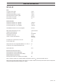
TECHNICAL DATA
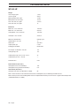
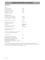
WS 440 HF
Note 1: Noise emissions in the environment measured as sound power (L
WA
) in conformity with EN 15027/A1.
Note 2: Noise pressure level according to EN 15027/A1. Reported data for noise pressure level has a typical statistical dispersion
(standard deviation) of 1.0 dB(A).
Weight
Saw carriage, kg/lbs 3,7/8,2
Saw unit, kg/lbs 25/55,1
Blade guard 800 mm, kg/lbs 13/28,7
Blade guard 1000 mm, kg/lbs 16/35,3
Track 1200 mm (47”) kg/lbs 9,5/20,9
Track 2000 mm (79”) kg/lbs 19
Blade size
Blade size - max, mm/inches 1200/47,2
Blade size - min, mm/inches 600/23,6
Starting blade - max, mm/inches 1000/39,4
Saw depth - max, mm/inch 530/20,9
Motor for saw blade drive PM High cycle
Spindle output - max, kW 13
Power train Gear drive
Output speed, rpm 0-1225
Feedingsystem/control Electric/auto
Drive torque at saw blade - max, Nm 125
Starting torque, Nm 100
Cooling water temp. in at 3,5 l/min - max, C 25
Cooling water pressure - max, bar 7
Protection class IP 65
Noise emissions (see note 1)
Sound power level, measured dB (A) 108
Sound power level, guaranteed L
WA
dB (A) 109
Sound levels (see note 2)
Sound pressure level at the operators ear, dB(A) 85

English – 19
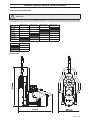
TECHNICAL DATA
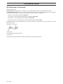
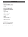
Recommended blade speed
Follow the blade manufacture´s recommendations regarding material and blade speed when choosing blade. A lower blade speed
should be used when cutting in hard concrete than if cutting in soft concrete.
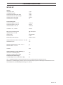
Dimensions
!
WARNING! Cutting at too high revs can cause damage to the blade and lead to personal injury.
600 mm (24”) 800 mm (32”) 1000 mm (40”) 1200 mm (48”)
600 rpm
700 rpm
800 rpm
900 rpm
1000 rpm
1100 rpm
1200 rpm
Concrete
Hard
Medium
Soft
423 mm

20 – English
TECHNICAL DATA
EC Declaration of Conformity
(Applies to Europe only)
Husqvarna AB, SE-561 82 Huskvarna, Sweden, tel: +46-36-146500, declares under sole responsibility that the wall
sawHusqvarna WS 440 HF , from 2010´s serial numbers and onwards (the year is clearly stated in plain text on the rating plate
with subsequent serial number), conforms with the requirements of the COUNCIL´S DIRECTIVE:
• of May 17, 2006 ”relating to machinery” 2006/42/EC.
• of December 15, 2004 ”relating to electromagnetic compatibility” 2004/108/EC.
• of December 12, 2006 ”relating to electrical equipment” 2006/95/EC.
• of June 08, 2011 on the 'restriction of use of certain hazardous substances' 2011/65/EU
The following standards have been applied: EN ISO 12100:2010, EN 55014-1:2006, EN 55014-2/A1:2001, EN 61000-3-11:2000,
EN 15027/A1:2009.
Gothenburg, 12 April 2015
Helena Grubb
Vice President, Construction Equipment
Husqvarna AB
(Authorized representative for Husqvarna AB and responsible for technical documentation.)
Seite wird geladen ...
Seite wird geladen ...
Seite wird geladen ...
Seite wird geladen ...
Seite wird geladen ...
Seite wird geladen ...
Seite wird geladen ...
Seite wird geladen ...
Seite wird geladen ...
Seite wird geladen ...
Seite wird geladen ...
Seite wird geladen ...
Seite wird geladen ...
Seite wird geladen ...
Seite wird geladen ...
Seite wird geladen ...
Seite wird geladen ...
Seite wird geladen ...
Seite wird geladen ...
Seite wird geladen ...
Seite wird geladen ...
Seite wird geladen ...
Seite wird geladen ...
Seite wird geladen ...
Seite wird geladen ...
Seite wird geladen ...
Seite wird geladen ...
Seite wird geladen ...
Seite wird geladen ...
Seite wird geladen ...
Seite wird geladen ...
Seite wird geladen ...
Seite wird geladen ...
Seite wird geladen ...
Seite wird geladen ...
Seite wird geladen ...
Seite wird geladen ...
Seite wird geladen ...
Seite wird geladen ...
Seite wird geladen ...
Seite wird geladen ...
Seite wird geladen ...
Seite wird geladen ...
Seite wird geladen ...
Seite wird geladen ...
Seite wird geladen ...
Seite wird geladen ...
Seite wird geladen ...
Seite wird geladen ...
Seite wird geladen ...
Seite wird geladen ...
Seite wird geladen ...
Seite wird geladen ...
Seite wird geladen ...
Seite wird geladen ...
Seite wird geladen ...
Seite wird geladen ...
Seite wird geladen ...
Seite wird geladen ...
Seite wird geladen ...
-
 1
1
-
 2
2
-
 3
3
-
 4
4
-
 5
5
-
 6
6
-
 7
7
-
 8
8
-
 9
9
-
 10
10
-
 11
11
-
 12
12
-
 13
13
-
 14
14
-
 15
15
-
 16
16
-
 17
17
-
 18
18
-
 19
19
-
 20
20
-
 21
21
-
 22
22
-
 23
23
-
 24
24
-
 25
25
-
 26
26
-
 27
27
-
 28
28
-
 29
29
-
 30
30
-
 31
31
-
 32
32
-
 33
33
-
 34
34
-
 35
35
-
 36
36
-
 37
37
-
 38
38
-
 39
39
-
 40
40
-
 41
41
-
 42
42
-
 43
43
-
 44
44
-
 45
45
-
 46
46
-
 47
47
-
 48
48
-
 49
49
-
 50
50
-
 51
51
-
 52
52
-
 53
53
-
 54
54
-
 55
55
-
 56
56
-
 57
57
-
 58
58
-
 59
59
-
 60
60
-
 61
61
-
 62
62
-
 63
63
-
 64
64
-
 65
65
-
 66
66
-
 67
67
-
 68
68
-
 69
69
-
 70
70
-
 71
71
-
 72
72
-
 73
73
-
 74
74
-
 75
75
-
 76
76
-
 77
77
-
 78
78
-
 79
79
-
 80
80


in anderen Sprachen
- English: Husqvarna WS 440 HF User manual
- français: Husqvarna WS 440 HF Manuel utilisateur
- español: Husqvarna WS 440 HF Manual de usuario
Verwandte Artikel
Andere Dokumente
-
Parkside 315581 Translation Of The Original Instructions
-
Parkside PTK 2000 C3 Translation Of The Original Instructions
-
Scheppach TS82 Translation Of Original Operating Manual
-
-
-
 Dimas FS 350 Benutzerhandbuch
-
 Lissmac LWSE 800 Bedienungsanleitung

