
HAGOR Products GmbH | Oberbecksener Straße 97 | D-32547 Bad Oeynhausen | Telefon: +49(0)57 31-7 55 07-0 | Mail: info@hagor.de
Installationsanleitung
CON-Line® W Lift 55 - 75“ | Art.-Nr.: 2812
DE Installationsanleitung
ES Guía de instalación
GB Installation manual
FR Guide d‘installation
SE Installationsanvisning
TR Yükleme Rehberi
RU инструкция по установке
NL Installatievoorschrift
CN 安装指南
Dieses Dokument ist Eigentum der HAGOR Products GmbH. Weitergabe sowie Vervielfältigung dieses Dokuments, Verwertung und Mitteilung seines Inhalts sind verboten, soweit nicht ausdrücklich gestattet.
Zuwiderhandlung verpichten zu Schadenersatz. Alle Rechte für den Fall der Patent-, Gebrauchsmuster- oder Geschmacksmustereintragung vorbehalten.
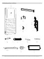
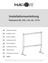
1800 mm
120
165
1000 mm
42
472 mm
min. 200 - max. 400 mm
750 mm

HAGOR Products GmbH | Oberbecksener Straße 97 | D-32547 Bad Oeynhausen | Telefon: +49(0)57 31-7 55 07-0 | Mail: info@hagor.de
DE
GB
Achtung!
Technische Geräte stellen einen beträchtlichen Wert dar. Sie sollten daher bei
der Installation vorsichtig mit den Komponenten umgehen und diese bei Bedarf
schützen.
Auch sollte, falls nötig, der Installtionsbereich abgesichert werden. Herabfallen-
de Teile können zu Verletzungen und Materialschäden führen.
Die im Lieferumfang enthaltenen Materialien sind unter Umständen nicht für die
speziellen Gegebenheiten am Installationsort geeignet. Bitte prüfen Sie dies
vorab und ersetzen Sie diese bei Bedarf durch geeignete Materialien.
Falls Sie Bezüglich der Installation des Produkts unsicher sind oder noch Fra-
gen haben wenden Sie sich an uns oder anderes ausgebildetes Fachpersonal.
Caution!
Technical devices are of considerable value. You should therefore handle the
components carefully during installation and protect them if necessary.
If necessary, the installation area should also be secured. Falling parts can cause
injuries and material damage.
The materials included in the scope of delivery may not be suitable for the spe-
cial conditions at the installation site. Please check this in advance and replace it
with suitable materials if necessary.
If you are unsure about the installation of the product or have any questions,
please contact us or other trained specialists.

HAGOR Products GmbH | Oberbecksener Straße 97 | D-32547 Bad Oeynhausen | Telefon: +49(0)57 31-7 55 07-0 | Mail: info@hagor.de
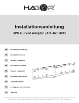
Lieferumfang | Scope of delivery
B
1x
E
2x
C
2x
D
2x
F
2x
M
1x
J
1x
J-2
1x
J-1
1x
L
1x
A
1x
Y
X
K 2x

HAGOR Products GmbH | Oberbecksener Straße 97 | D-32547 Bad Oeynhausen | Telefon: +49(0)57 31-7 55 07-0 | Mail: info@hagor.de
a 2x
Ø 8
c 8x
M8x10
i 2x
M5x8
j 5x
15 mm
d 10x
b 2x
M8x10
h 4x
M6
f 10x
4,0x16
g 4x
M6x20
M-A 4x
M5x14
M-B 4x
M6x14
M-C 4x
M6x30 M-E 4x
M8x50
M-D 4x
M8x30
M-F 4x M-G 8x M-H 8x
e 8x
Ø 6
k 8x
M6x40
l 8x
M6x60
m 1x

HAGOR Products GmbH | Oberbecksener Straße 97 | D-32547 Bad Oeynhausen | Telefon: +49(0)57 31-7 55 07-0 | Mail: info@hagor.de
1
A
Nehmen Sie die untere Frontblende ab. Die Frontblende ist durch eine Magnetarretierung xiert.
Take off the lower front panel. The front panel is xed by a magnet lock.

HAGOR Products GmbH | Oberbecksener Straße 97 | D-32547 Bad Oeynhausen | Telefon: +49(0)57 31-7 55 07-0 | Mail: info@hagor.de
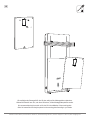
2
Nehmen Sie die obere Frontblende ab. Diese ist auch über Magnetverriegelung sowie Lamellos gesichert.
Hierbei ist darauf zu achten, dass die Platte gleichmäßig nach vorne herausgezogen wird und NICHT einseitig nach oben.
Take off the upper front panel. The front panel is xed by a magnet lock.
The panel is also secured with a magnetic lock as well as with Lamellos.
It is important to ensure that the panel is pulled out evenly towards the front and NOT upwards on one side.
A

HAGOR Products GmbH | Oberbecksener Straße 97 | D-32547 Bad Oeynhausen | Telefon: +49(0)57 31-7 55 07-0 | Mail: info@hagor.de
Verschraubung der Montageplatte von der Rückwand lösen und herausnehmen.
Loosen the screw connection of the mounting plate from the rear panel and take it out.
3
1
2
1
2
A
A

HAGOR Products GmbH | Oberbecksener Straße 97 | D-32547 Bad Oeynhausen | Telefon: +49(0)57 31-7 55 07-0 | Mail: info@hagor.de
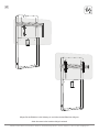
4
Setzen sie die beiden Hublifte ein und Schrauben sie diese oben und unten fest.
Bitte achten sie darauf die Kabel nicht zu quetschen!
Nutzen sie die Kabelausbuchtungen unten am Lift und die Kabeldurchführung im Korpus.
Insert the two lifts and screw them tight at the top and bottom.
Please be careful not to squeeze the cables!
Use the cable bulges at the bottom of the lift and the cable feedthrough in the corpus.
A
K
K
k
l

HAGOR Products GmbH | Oberbecksener Straße 97 | D-32547 Bad Oeynhausen | Telefon: +49(0)57 31-7 55 07-0 | Mail: info@hagor.de
5
Setzen sie die obere Frontplatte wieder ein.
Replace the upper front panel.
A

HAGOR Products GmbH | Oberbecksener Straße 97 | D-32547 Bad Oeynhausen | Telefon: +49(0)57 31-7 55 07-0 | Mail: info@hagor.de
6
A
Richten Sie das Möbel aus indem Sie die Stellfüsse (vormontiert) mit
einem Inbusschlüssel herein- oder heraus drehen.
Align the corpus by turning the adjustable feet (pre-assembled) in or out with an Allen key.

HAGOR Products GmbH | Oberbecksener Straße 97 | D-32547 Bad Oeynhausen | Telefon: +49(0)57 31-7 55 07-0 | Mail: info@hagor.de
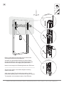
7
Montagematerial zur Wandmontage ist nicht im Lieferumfang enthalten. Verwenden Sie nur Montage-
materialien, die für den Zweck und die Art der Wand geeignet sind. Prüfen Sie die Festigkeit der ver-
wendeten Dübel und Schrauben. Wenn eine Fußleiste vorhanden ist, verwenden Sie bitte zusätzlich
die Abstandshalter (j). Bei Leichbauwänden empfehlen wir die Verwendung des zusätzlichen Montage-
punktes. Entfernen Sie den oberen Kabeldurchlass um die Bohrung zu erreichen.
Mounting material for wall mounting is not included in the scope of delivery. Use only mounting materials
which is suitable for the purpose and type of wall. Check the strength of the anchors and screws you use.
If there is a skirting board, please add the spacers (j). For wood stud walls, we recommend using the
additional mounting point. Remove the top cable grommet to access the hole.
A

HAGOR Products GmbH | Oberbecksener Straße 97 | D-32547 Bad Oeynhausen | Telefon: +49(0)57 31-7 55 07-0 | Mail: info@hagor.de
8
Y
X
Y
X
Y
X
Y-Achse muss nach
oben ausgerichtet
sein.
!
Montieren sie den Kollisionswarner rückseitig an einem Aufnahmewinkel. Je nach geplanter Position des Tastschalters rechts oder links.
Mount the collision warner on the back of a mounting bracket. Depending on the position of the pushbutton place it on the right or left.
L + i
A
C
C
L

HAGOR Products GmbH | Oberbecksener Straße 97 | D-32547 Bad Oeynhausen | Telefon: +49(0)57 31-7 55 07-0 | Mail: info@hagor.de
9
Y
X
Y
X
Y
X
Y-Achse muss nach
oben ausgerichtet
sein.
!
Setzen sie die Aufnahmewinkel nun von innen an die Liftnne und schrauben sie diese wie oben im Detailbild gezeigt fest.
Now place the mounting brackets on the inside of the lift n and screw them tight as shown in the detailed picture above.
C
C e geh
A

HAGOR Products GmbH | Oberbecksener Straße 97 | D-32547 Bad Oeynhausen | Telefon: +49(0)57 31-7 55 07-0 | Mail: info@hagor.de
10
Schrauben sie die Nutensteine auf die Aufnahmewinkel und ziehen sie die Schrauben noch nicht ganz fest.
Screw the sliding block on the mounting brackets and do not fully tighten the screws yet.
c
d
C
A

HAGOR Products GmbH | Oberbecksener Straße 97 | D-32547 Bad Oeynhausen | Telefon: +49(0)57 31-7 55 07-0 | Mail: info@hagor.de
11
Schieben sie das Rail über die Nutensteine, richten sie es mittig aus und ziehen sie die Schrauben nun richtig fest.
Slide the rail over the sliding blocks, center the rail and tighten the screws properly now.
B
A

HAGOR Products GmbH | Oberbecksener Straße 97 | D-32547 Bad Oeynhausen | Telefon: +49(0)57 31-7 55 07-0 | Mail: info@hagor.de
12
d
F
F
F
a
b
Die Nutensteine in die Schiene schieben, Kappen aufsetzen und beides festschrauben. Auf der anderen Seite ebenso.
Diese Sicherung verhindert, dass der Bildschirm seitlich aus der Schiene geschoben werden kann.
Slide the slot nuts into the rail, put on the caps and screw both tight. On the other side as well.
This protection prevents the screen from being pushed out of the rail to the side.
B
B
B
A
B

HAGOR Products GmbH | Oberbecksener Straße 97 | D-32547 Bad Oeynhausen | Telefon: +49(0)57 31-7 55 07-0 | Mail: info@hagor.de
H
H
13a
13b
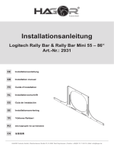
M-A
M-F
M-B
M-F
TV TV TV
TV TV TV
M-F
M-G
M-C
M-D
M-F
M-D
M-C
M-H
M-F
M-D
M-C
M-H
M-G
M-F
M-E
M-H
M-G
M-F
M-E
M-H
M-G
M-F
M-E
M-H
M-A
M-F
M-B
M-F
TV TV TV
TV TV TV
M-F
M-G
M-C
M-D
M-F
M-D
M-C
M-H
M-F
M-D
M-C
M-H
M-G
M-F
M-E
M-H
M-G
M-F
M-E
M-H
M-G
M-F
M-E
M-H
Montage an einem Bildschirm mit acher Rückseite | Installation on a TV with at back
Montage an einem Bildschirm mit gewölbter Rückseite | Installation on a TV with irregular back

HAGOR Products GmbH | Oberbecksener Straße 97 | D-32547 Bad Oeynhausen | Telefon: +49(0)57 31-7 55 07-0 | Mail: info@hagor.de
Empfehlung | Recommendation
Um eine saubere Verlegung der Kabel zu gewährleisten empfehlen wir die Verwendung unseres Kabelstrumpfsortiments.
Diese sind in unterschiedlichen Ausführungen erhältlich. Weitere Infos erhalten sie, wenn sie den QR-Code scannen.
To ensure that the cables are laid neatly, we recommend using our cable organizers.
These are available in different versions. You can get more information by scanning the QR code.
https://hagor.net/produkt-kategorie/
cable-management/cable-socks/
https://hagor.de/produkt-kategorie/
kabelmanagement/kabelstruempfe/

HAGOR Products GmbH | Oberbecksener Straße 97 | D-32547 Bad Oeynhausen | Telefon: +49(0)57 31-7 55 07-0 | Mail: info@hagor.de
14
Öffnen sie das Clip-Gehäuse mit einem kleinen Schlitz-
schraubendreher.
Legen sie die Kabel in die Gummikabeltüllen ein und
schieben sie sie wieder in die Kabelverschraubung.
Achten sie darauf, dass die glatten Flächen der Kabeltüllen
aufeinander liegen wie im Bild unten rechts markiert.
Schieben sie die Kabelführung in den Korpus.
Achten sie darauf die Kabel nicht zu verdrehen oder
einzuquetschen.
Die Kabellängen sollten vom Austrittspunkt bis zum
Geräteanschluss +50 cm Kabellänge aufweisen.
---------------------------------------------------------------------------------
Open the clip housing with a small slotted screwdriver.
Insert the cables into the gummi cable grommets and
push them back into the cable gland.
Make sure that the smooth surfaces of the cable grommets
are on top of each other as shown in the picture on the right.
The cable lengths should be +50 cm cable length from the
exit point to the device connection.
Slide the cable guide into the corpus.
Be careful not to twist or squeeze the cables.
m
m
m

HAGOR Products GmbH | Oberbecksener Straße 97 | D-32547 Bad Oeynhausen | Telefon: +49(0)57 31-7 55 07-0 | Mail: info@hagor.de
15
2
1
2
1
Wir empfehlen das Steuergerät für den Lift oben mittig auf der Montageplatte zu platzieren.
Weiteres AV-Zubehör kann frei, nach Ihren Wünschen, auf der Montageplatte platziert werden.
We recommend placing the control unit for the lift in the middle/top of the mounting plate.
Other AV accessories can freely be placed on the mounting plate according to your needs.
f
M
Seite wird geladen ...
Seite wird geladen ...
Seite wird geladen ...
Seite wird geladen ...
Seite wird geladen ...
Seite wird geladen ...
Seite wird geladen ...
Seite wird geladen ...
Seite wird geladen ...
Seite wird geladen ...
Seite wird geladen ...
Seite wird geladen ...
-
 1
1
-
 2
2
-
 3
3
-
 4
4
-
 5
5
-
 6
6
-
 7
7
-
 8
8
-
 9
9
-
 10
10
-
 11
11
-
 12
12
-
 13
13
-
 14
14
-
 15
15
-
 16
16
-
 17
17
-
 18
18
-
 19
19
-
 20
20
-
 21
21
-
 22
22
-
 23
23
-
 24
24
-
 25
25
-
 26
26
-
 27
27
-
 28
28
-
 29
29
-
 30
30
-
 31
31
-
 32
32


in anderen Sprachen
- English: Hagor 2812 Owner's manual
Verwandte Artikel
-
 Hagor 3240 Bedienungsanleitung
-
 Hagor 3346 Bedienungsanleitung
-
 Hagor CON-Line T1 Benutzerhandbuch
-
 Hagor 2385479 Benutzerhandbuch
-
 Hagor 8719 Bedienungsanleitung
-
 Hagor 2805 Bedienungsanleitung
-
 Hagor 2809 Bedienungsanleitung
-
 Hagor 3249 Bedienungsanleitung
-
Hagor 1956 Installationsanleitung
-
 Hagor 2931 Bedienungsanleitung


