Fagor CH-ARG90X Bedienungsanleitung
- Kategorie
- Dunstabzugshauben
- Typ
- Bedienungsanleitung

IT Istruzioni di montaggio e d'uso
DE Montage- und Gebrauchsanweisung
EN Instruction on mounting and use
FR Prescriptions de montage et mode d’emploi
NL Montagevoorschriften en gebruiksaanwijzingen
ES Montaje y modo de empleo
PT Instruções para montagem e utilização
RU Инструкции по монтажу и эксплуатации


5
IT - Istruzioni di montaggio e d'uso
Consultare anche i disegni nelle prime pagine con i riferimenti
alfabetici riportati nel testo esplicativo.
Attenersi strettamente alle istruzioni riportate in questo
manuale. Si declina ogni responsabilità per eventuali
inconvenienti, danni o incendi provocati all'apparecchio
derivati dall'inosservanza delle istruzioni riportate in questo
manuale.
Nota: I particolari contrassegnati con il simbolo "(*)" sono
accessori opzionali forniti solo in alcuni modelli o particolari
non forniti, da acquistare.
Avvertenze
Attenzione! Non collegare l’apparecchio alla rete elettrica
finche l’installazione non è totalmente completata.
Prima di qualsiasi operazione di pulizia o manutenzione,
disinserire la cappa dalla rete elettrica togliendo la spina o
staccando l’interruttore generale dell’abitazione.
L’apparecchio non è destinato all’utilizzo da parte di bambini o
persone con ridotte capacità fisiche sensoriali o mentali e con
mancata esperienza e conoscenza a meno che essi non siano
sotto la supervisione o istruiti nell’uso dell’apparecchiatura da
una persona responsabile per la loro sicurezza.
I bambini devono essere controllati affinché non giochino con
l’apparecchio.
Mai utilizzare la cappa senza griglia correttamente montata!
La cappa non va MAI utilizzata come piano di appoggio a
meno che non sia espressamente indicato.
Il locale deve disporre di sufficiente ventilazione, quando la
cappa da cucina viene utilizzata contemporaneamente ad altri
apparecchi a combustione di gas o altri combustibili.
L’aria aspirata non deve essere convogliata in un condotto
usato per lo scarico dei fumi prodotti da apparecchi a
combustione di gas o di altri combustibili.
E’ severamente vietato fare cibi alla fiamma sotto la cappa.
L’impiego di fiamma libera è dannoso ai filtri e può dar luogo
ad incendi, pertanto deve essere evitato in ogni caso.
La frittura deve essere fatta sotto controllo onde evitare che
l’olio surriscaldato prenda fuoco.
Per quanto riguarda le misure tecniche e di sicurezza da
adottare per lo scarico dei fumi attenersi strettamente a
quanto previsto dai regolamenti delle autorità locali
competenti.
La cappa va frequentemente pulita sia internamente che
esternamente (ALMENO UNA VOLTA AL MESE, rispettare
comunque quanto espressamente indicato nelle istruzioni di
manutenzione riportate in questo manuale).
L’inosservanza delle norme di pulizia della cappa e della
sostituzione e pulizia dei filtri comporta rischi di incendi.
Non utilizzare o lasciare la cappa priva di lampade
correttamente montate per possibile rischio di scossa elettrica.
Si declina ogni responsabilità per eventuali inconvenienti,
danni o incendi provocati all’apparecchio derivati
dall’inosservanza delle istruzioni riportate in questo manuale.
Questo apparecchio è contrassegnato in conformità alla
Direttiva Europea 2002/96/EC, Waste Electrical and Electronic
Equipment (WEEE). Assicurandosi che questo prodotto sia
smaltito in modo corretto, l'utente contribuisce a prevenire le
potenziali conseguenze negative per l'ambiente e la salute.
Il simbolo
sul prodotto o sulla documentazione di
accompagnamento indica che questo prodotto non deve
essere trattato come rifiuto domestico ma deve essere
consegnato presso l'idoneo punto di raccolta per il riciclaggio
di apparecchiature elettriche ed elettroniche. Disfarsene
seguendo le normative locali per lo smaltimento dei rifiuti. Per
ulteriori informazioni sul trattamento, recupero e riciclaggio di
questo prodotto, contattare l'idoneo ufficio locale, il servizio di
raccolta dei rifiuti domestici o il negozio presso il quale il
prodotto è stato acquistato.
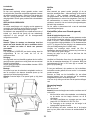
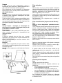
Utilizzazione
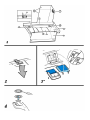
La cappa è realizzata per essere utilizzata in versione
aspirante ad evacuazione esterna o filtrante a ricircolo interno.
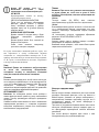
Versione aspirante
La cappa è fornita di una uscita d‘aria superiore B per lo
scarico dei fumi verso l'esterno ( tubo di scarico e fascette di
fissaggio non fornite).
Attenzione!
Se la cappa e’ provvista di filtro al carbone, questo deve
essere tolto.
Versione filtrante
Nel caso non sia possibile scaricare i fumi e vapori della
cottura verso l‘esterno, si può utilizzare la cappa in versione
filtrante montando un filtro ai carboni attivi e il deflettore F sul
supporto (staffa) G, i fumi e vapori vengono depurati
attraverso la sgrigliatura superiore H tramite un tubo di scarico
collegato all‘uscita d‘aria superiore B e l‘anello di connessione
montato sul deflettore F (tubo di scarico e fascette di fissaggio
non fornite).
Attenzione!
Se la cappa non è provvista di filtro al carbone, questo
deve essere ordinato e montato prima dell’uso.
I modelli senza motore di aspirazione funzionano solo in
versione aspirante e debbono essere collegati ad una unità
periferica di aspirazione (non fornita).
Installazione
La distanza minima fra la superficie di supporto dei recipienti
sul dispositivo di cottura e la parte più bassa della cappa da
cucina deve essere non inferiore a 50cm in caso di cucine
elettriche e di 65cm in caso di cucine a gas o miste.
Se le istruzioni di installazione del dispositivo di cottura a gas
specificano una distanza maggiore, bisogna tenerne conto.
Collegamento Elettrico
La tensione di rete deve corrispondere alla tensione riportata
sull’etichetta caratteristiche situata all’interno della cappa. Se
provvista di spina allacciare la cappa ad una presa conforme

6
alle norme vigenti posta in zona accessibile. Se sprovvista di
spina (collegamento diretto alla rete) o la spina non è posta in
zona accessibile applicare un interruttore bipolare a norma
che assicuri la disconnessione completa della rete nelle
condizioni della categoria di sovratensione III, conformemente
alle regole di installazione.
Attenzione: prima di ricollegare il circuito della cappa
all’alimentazione di rete e di verificarne il corretto
funzionamento, controllare sempre che il cavo di rete sia stato
montato correttamente.
Montaggio
Prima di iniziare con l'installazione:
• Verificare che il prodotto acquistato sia di dimensioni
idonee alla zona di installazione prescelta.
• Per agevolare l'installazione, si consiglia di rimuovere
temporaneamente i filtri grassi e gli altri componenti
smontabili come descritto nei paragrafi relativi.
Questi vanno rimontati ad installazione ultimata.
• Togliere il/i filtro/i al carbone attivo se forniti (vedi anche
paragrafo relativo). Questo/i va/nno rimontato/i solo se si
vuole utilizzare la cappa in versione filtrante.
• Verificare che all'interno della cappa non vi sia (per motivi
di trasporto) materiale di corredo (ad esempio buste con
viti, garanzie etc) , eventualmente toglierle e conservarle.
• Se possibile scollegare e rimuovere i mobili sottostanti ed
intorno l’area di installazione della cappa in modo da
avere una migliore accessibilità al/alla soffitto/parete
dove la cappa verrà installata. Altrimenti proteggere per
quanto possibile i mobili e tutte le parti interessate
all'installazione. Scegliere una superficie piatta e coprirla
con una protezione dove poi appoggiare la cappa e i
particolari a corredo.
• Scollegare la cappa agendo sul quadro generale
domestico nelle fasi del collegamento elettrico.
• Verificare inoltre che in prossimità della zona di
installazione della cappa (in zona accessibile anche con
cappa montata) sia disponibile una presa elettrica e sia
possibile collegarsi ad un dispositivo di scarico fumi
verso l'esterno (solo Versione aspirante).
• Eseguire tutti i lavori di muratura necessari (ad es.:
installazione di una presa elettrica e/o foro per il
passaggio del tubo di scarico).
La cappa è dotata di tasselli di fissaggio adatti alla maggior
parte di pareti/soffitti. E’ tuttavia necessario interpellare un
tecnico qualificato per accertarVi sull’idoneità dei materiali a
seconda del tipo di parete/soffitto. La/il parete/soffitto deve
essere sufficientemente robusto da sostenere il peso della
cappa.
Attenzione! Il camino è predisposto per l'installazione in
Versione filtrante
In alcuni modelli nel caso si volesse utilizzare la cappa in
Versione aspirante si può capovolgere la sezione superiore
del camino sino ad inserirla all'interno della sezione inferiore
del camino in modo che le asole di uscita aria non siano più
visibili. I camini in cui tale operazione è possibile sono
riconoscibili perché i punti di fissaggio alla staffa G sono
ripetuti anche nel lato inferiore della sezione superiore del
camino.
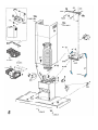
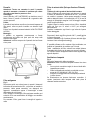
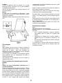
Installazione modello per parete
Fig. 5
1. Con una matita, eseguire una linea sulla parete, sino al
soffitto, corrispondente alla linea di mezzeria, faciliterà le
operazioni di installazione.
2. Applicare lo schema di foratura al muro: la linea verticale
di mezzeria stampata sullo schema di foratura dovrà
corrispondere alla linea di mezzeria disegnata sul muro,
inoltre il bordo inferiore dello schema di foratura
corrisponde al bordo inferiore della cappa.
3. Appoggiare la staffa di supporto inferiore sullo schema di
foratura facendolo coincidere con il rettangolo
tratteggiato, segnare i due fori esterni e forare, togliere lo
schema di foratura, inserire 2 tasselli a muro e fissare
con 2 viti 5x45mm la staffa di supporto della cappa.
4. Appendere la cappa alla staffa inferiore.
5. Regolare la distanza della cappa dalla parete.
6. Regolare l’assetto orizzontale della cappa.
7. Dall’interno del gruppo aspirante , segnare con una
matita il foro per il fissaggio definitivo della cappa (sono
necessari 2 punti di fissaggio definitivo).
8. Togliere la cappa dalla staffa inferiore.
9. Forare nel punto marcato (2 x Ø8mm).
10. Inserire 2 tasselli a muro.
11. Applicare la staffa di supporto camini „G“ alla parete
aderente al soffitto, utilizzare la staffa di supporto camini
come schema di foratura (se presente, la piccola asola
ricavata sul supporto deve coincidere con la linea
precedentemente tracciata sul muro) e segnare con la
matita 2 fori, eseguire i fori (Ø8mm), inserire 2 tasselli.
12. Fissare la staffa di supporto camini alla parete con 2 viti
5x45mm.
13. Agganciare la cappa alla staffa inferiore.
14. Fissare definitivamente la cappa alla parete
(OBBLIGATORIO!!).
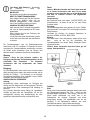
15. Eseguire la connessione di un tubo (tubo e fascette per il
fissaggio non fornite, da acquistare) per lo scarico dei
fumi all’anello di connessione posto sopra l’unità motore
aspirante.
L’altra estremità del tubo dovrà essere collegata ad un
dispositivo di espulsione fumi verso l’esterno in caso di
utilizzo della cappa in versione aspirante. Nel caso si
voglia utilizzare la cappa in versione filtrante, allora
fissare alla staffa di supporto camini G il deflettore F e
collegare l’altra estremità del tubo all’anello di
connessione posto sul deflettore F.
16. Eseguire la connessione elettrica.
17. Inserire il camino nella apposita sede sopra la cappa a
copertura completa del gruppo aspirante.
18. Fissare la sezione inferiore del camino con due viti.
19. Fissarlo sopra con 2 viti (19a) alla staffa di supporto
camini „G“ (19b).
Rimontare il telaio del filtro al carbone e il/i filtro/i grassi e
controllare il perfetto funzionamento della cappa.

7
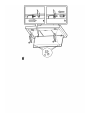
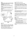
Installazione del pannello
(numero e forma dei pannelli può variare in base al modello)
Il panello viene fornito a corredo.
Agganciare il pannello sui perni della cappa e fissare con il
nottolino S fornito a corredo (il numero varia in base al
modello - fissaggio di sicurezza obbligatorio!).
Ruotare i pannelli a copertura dell'area di aspirazione, ed
agganciarlo ai perni premendo con decisione.
Verificare che il pannello sia bloccato in posizione. Fig. 6
Descrizione della cappa
Fig. 1
1. Pannello di controllo
2. Filtro antigrasso
3. Maniglia di sgancio del filtro antigrasso
4. Lampada alogena
5. Schermo vapori
6. Camino telescopico
7. Uscita aria (solo per utilizzo in versione filtrante)
8. Pannello
Funzionamento
Usare la velocità maggiore in caso di particolare
concentrazione di vapori di cucina. Consigliamo di accendere
l'aspirazione 5 minuti prima di iniziare a cucinare e di lasciarla
in funzione a cottura terminata per altri 15 minuti circa.
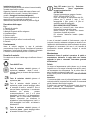
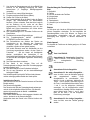
Pannello di controllo
Per selezionare le funzioni della cappa è sufficente sfiorare i
comandi.
Tasto ON/OFF luce
Tasto di selezione velocità (potenza di
aspirazione) intensiva - durata 5 minuti -
premere ancora per ritornare alla impostazione
precedente.
Tasto di selezione velocità (potenza di
aspirazione) alta
Tasto di selezione velocità (potenza di
aspirazione) media- quando lampeggia indica
la necessita di lavare o sostituire il filtro al
carbone.Questa segnalazione è normalmente
disattivata, per attivarla premere
contemporaneamente i tasti 1 e 2, prima
lampeggerà il solo tasto 1 poi lampeggeranno
entrambi i tasti 1 e 2 ad indicare l’attivazione.
Ripetere l’operazione per disattivare la
segnalazione, prima lampeggeranno i tasti 1 e
2 poi lampeggerà il solo tasto 1 ad indicare la
disattivazione.
Tasto di selezione velocità (potenza di
aspirazione) bassa - quando lampeggia indica
la necessita di lavare il filtro grassi.
Tasto OFF motore (stand by) - Esclusione
dell’Elettronica - Reset segnalazione
lavaggio/sostituzione filtri.
OFF MOTORE
Premere brevemente per spegnere il motore.
RESET SEGNALAZIONE FILTRI
Dopo aver eseguito la manutenzione dei filtri,
premere per 3 secondi il tasto, il led
lampeggiante 1 (filtro grassi) o 2 (filtro al
acarbone) smette di lampeggiare.
ESCLUSIONE DELL’ELETTRONICA
Premere per 3 secondi il tasto, viene esclusa
l’elettronica di comando della cappa.
Questa funzione può essere utile durante
l’operazione di pulizia del prodotto.
Per reinserire l’elettronica basterà ripetere
l’operazione.
In caso di eventuali anomalie di funzionamento, prima di
rivolgersi al servizio assistenza scollegare per almeno 5 sec.
l’apparecchio dall’alimentazione elettrica estraendo la spina e
collegatelo poi nuovamente. Nel caso in cui l’anomalia di
funzionamento dovesse perdurare, rivolgersi al servizio
d’assistenza.
Manutenzione
Attenzione! Prima di qualsiasi operazione di pulizia o
manutenzione, disinserire la cappa dalla rete elettrica
togliendo la spina o staccando l’interruttore generale
dell’abitazione.
Pulizia
La cappa va frequentemente pulita (almeno con la stessa
frequenza con cui si esegue la manutenzione dei filtri grassi),
sia internamente che esternamente. Per la pulizia usare un
panno inumidito con detersivi liquidi neutri.
Evitare l’uso di prodotti contenenti abrasivi. NON UTILIZZARE
ALCOOL!
Attenzione:
L’inosservanza delle norme di pulizia dell’apparecchio e della
sostituzione dei filtri comporta rischi di incendi. Si raccomanda
quindi di attenersi alle istruzioni suggerite.
Si declina ogni responsabilità per eventuali danni al motore,
incendi provocati da un’impropria manutenzione o
dall’inosservanza delle suddette avvertenze.

8
Pannello
Attenzione! Tenete con entrambe le mani il pannello
quando lo smontate o rimontate in posizione per evitare
che cada e causi danni a persone o cose.
Smontaggio:
tirare il pannello (LATO ANTERIORE) con decisione verso il
basso, svitare il pomello di sicurezza S e sganciarlo dalle
cerniere posteriori.
Pulizia:
il pannello di aspirazione va pulito con la stessa frequenza del
filtro grassi, usare un panno inumidito con detersivi liquidi
neutri.
Evitare l’uso di prodotti contenenti abrasivi. NON UTILIZZARE
ALCOOL!
Montaggio :
Il pannello va agganciato posteriormente e fissato
anteriormente ad incastro nei perni posti allo scopo sulla
superfice della cappa.
Attenzione! verificare sempre che il pannello sia ben fissato
al suo posto.
Filtro antigrasso
Fig. 2
Deve essere pulito una volta al mese (o quando il sistema di
indicazione di saturazione dei filtri - se previsto sul modello in
possesso- indica questa necessità), con detergenti non
aggressivi, manualmente oppure in lavastoviglie a basse
temperature ed a ciclo breve.
Con il lavaggio in lavastoviglie il filtro antigrasso metallico può
scolorirsi ma le sue caratteristiche di filtraggio non cambiano
assolutamente.
Per smontare il filtro grassi tirare la maniglia di sgancio a
molla.
Filtro ai carboni attivi (Solo per Versione Filtrante)
Fig. 3
Trattiene gli odori sgradevoli derivanti dalla cottura.
Il filtro al carbone può essere lavato ogni due mesi (o quando
il sistema di indicazione di saturazione dei filtri - se previsto
sul modello in possesso- indica questa necessità) in acqua
calda e detergenti idonei o in lavastoviglie a 65°C (in caso di
lavaggio in lavastoviglie eseguire il ciclo di lavaggio completo
senza stoviglie all'interno).
Togliere l'acqua in eccesso senza rovinare il filtro, dopodiché
riporlo nel forno per 10 minuti a 100°C per asciugarlo
definitivamente.
Sostituire il materassino ogni 3 anni e ogni volta che il panno
risulta danneggiato.
Rimuovere il telaio reggi filtro girando di 90° i pomelli (g) che
lo fissano alla cappa.
Inserire il materassino (i) di carbone all'interno del telaio (h) e
rimontare il tutto nella apposita sede (j).
E' possibile utilizzare un filtro carbone di tipo tradizionale, non
lavabile ne' rigenerabile, da sostituire ogni 3-4 mesi.
Telaio materassino del filtro carbone sono saldati insieme,
l'eventuale telaio fornito con la cappa non va perciò utilizzato.
Per l'utilizzo inserire nell'apposita sede e fissare agendo sugli
appositi dispositivi.
Sostituzione Lampade
Fig. 4
Disinserire l’apparecchio dalla rete elettrica.
Attenzione! Prima di toccare le lampade sincerarsi che siano
fredde.
• Con un piccolo cacciavite a taglio, far leva sui bordi della
lampadina per estrarla.
• Sfilare la lampadina da sostituire e sostituirla con una
nuova da 12V 20W MAX 30° Ø35 12V GU4.
• Eseguire il montaggio della nuova lampada procedendo
in senso inverso.
Se l'illuminazione non dovesse funzionare, controllate il
corretto inserimento delle lampade nella sede prima di
chiamare l'assistenza tecnica.

9
DE - Montage- und Gebrauchsanweisung
Bitte nehmen Sie auch die Abbildungen auf den ersten Beiden
Seiten mit den alphabetischen Bezeichnungen, die im Text
wiedergegeben sind, zur Hilfe.
Die Instruktionen, die in diesem Handbuch, gegeben
werden, sind bitte ganz streng einzuhalten. Es wird
keinerlei Haftung übernommen für mögliche Mängel, Schäden
oder Brände der Küchenhaube, die auf die Nichtbeachtung
der Vorschriften in diesem Handbuch zurückzuführen sind.
Hinweis: Die mit dem (*) gekennzeichneten Teile sind
Zubehörteile, die nur bei einigen Modellen im Lieferumfang
enthalten oder Teile, die nicht im Lieferumfang enthalten sind,
und somit extra erworben werden müssen.
Warnung
Achtung! Das Gerät nicht an das Stromnetz anschließen,
solange die Installation noch nicht abgeschlossen ist.
Vor Beginn sämtlicher Reinigungs- oder Wartungsarbeiten
muss das Gerät durch Ziehen des Steckers oder Betätigen
des Hauptschalters der Wohnung vom Stromnetz getrennt
werden.
Das Gerät ist nicht zur Verwendung durch Kinder oder
Personen mit eingeschränkten körperlichen, geistigen oder
Wahrnehmungsfähigkeiten und mit mangelnder Erfahrung
oder Kenntnis geeignet, es sei denn unter Aufsicht oder
Anleitung zum Gebrauch durch eine für ihre Sicherheit
verantwortliche Person.
Kinder müssen beaufsichtigt werden, dass sie nicht mit dem
Gerät spielen.
Die Dunstabzugshaube niemals ohne korrekt montiertes Gitter
in Betrieb setzen!
Die Dunstabzugshaube darf NIEMALS als Abstellfläche
verwendet werden, sofern dies nicht ausdrücklich angegeben
wird.
Der Raum muss über eine hinreichende Belüftung verfügen,
wenn die Dunstabzugshaube mit anderen gas- oder
brennstoffbetriebenen Geräten gleichzeitig verwendet wird.
Bei gleichzeitigem Betrieb der Dunstabzugshaube im
Abluftbetrieb und Feuerstätten darf im Aufstellraum der
Feuerstätte der Unterdruck nicht größer als 4 Pa (4 x 10
-5
bar) sein.
Die angesaugte Luft darf nicht in Rohre geleitet werden, die
für die Ableitung der Abgase von gas- oder
brennstoffbetriebenen Geräten genutzt werden.
Es ist strengstens verboten, unter der Haube mit offener
Flamme zu kochen.
Eine offene Flamme beschädigt die Filter und kann Brände
verursachen, daher ist dies in jedem Fall zu vermeiden.
Das Frittieren muss unter Aufsicht erfolgen, um zu vermeiden,
dass das überhitzte Öl Feuer fängt.
In Bezug auf technische und Sicherheitsmaßnahmen für die
Ableitung der Abluft sind die Vorschriften der zuständigen
örtlichen Behörden strengstens einzuhalten.
Die Haube muss regelmäßig innen und außen gereinigt
werden (MINDESTENS EINMAL IM MONAT, diesbezüglich
sind in jedem Fall die ausdrücklichen Angaben in der
Wartungsanleitung dieses Handbuchs zu beachten).
Eine Nichtbeachtung der Vorschriften zur Reinigung der
Haube sowie zur Auswechselung und Reinigung der Filter
führt zu Brandgefahr.
Um das Risiko eines Stromschlages zu vermeiden, darf die
Dunstabzugshaube ohne richtig eingesetzte Lampen nicht
betrieben werden.
Es wird keinerlei Haftung übernommen für Fehler, Schäden
oder Brände des Gerätes, die durch Nichteinhaltung der in
diesem Handbuch aufgeführten Anweisungen verschuldet
wurden.
In Übereinstimmung mit den Anforderungen der Europäischen
Richtlinie 2002/96/EG über Elektro- und Elektronik-Altgeräte
(WEEE) ist vorliegendes Gerät mit einer Markierung
versehen.
Sie leisten einen positiven Beitrag für den Schutz der Umwelt
und die Gesundheit des Menschen, wenn Sie dieses Gerät
einer gesonderten Abfallsammlung zuführen. Im unsortierten
Siedlungsmüll könnte ein solches Gerät durch unsachgemäße
Entsorgung negative Konsequenzen nach sich ziehen.
Auf dem Produkt oder der beiliegenden
Produktdokumentation ist folgendes Symbol
einer
durchgestrichenen Abfalltonne abgebildet. Es weist darauf
hin, dass eine Entsorgung im normalen Haushaltsabfall nicht
zulässig ist. Entsorgen Sie dieses Produkt im Recyclinghof mit
einer getrennten Sammlung für Elektro- und Elektronikgeräte.
Die Entsorgung muss gemäß den örtlichen Bestimmungen zur
Abfallbeseitigung erfolgen.
Bitte wenden Sie sich an die zuständigen Behörden Ihrer
Gemeindeverwaltung, an den lokalen Recyclinghof für
Haushaltsmüll oder an den Händler, bei dem Sie dieses Gerät
erworben haben, um weitere Informationen über Behandlung,
Verwertung und Wiederverwendung dieses Produkts zu
erhalten.
Betriebsart
Die Haube kann sowohl als Abluftgërat als auch als
Umluftgërat eingesetzt werden.
Abluftbetrieb
Die Haube verfügt über einen oberen Luftaustritt B zum
Ableiten der Küchengerüche nach außen (Abluftrohr und
Rohrschellen werden nicht geliefert).
Achtung!
Sollte die Dunstabzugshaube mit einem Aktivkohlefilter
versehen sein, so muß dieser entfernt werden.
Umluftbetrieb
Ist eine Ableitung von Rauch und Kochdämpfen ins Freie nicht
möglich, kann die Haube mit Umluftbetrieb arbeiten; in
diesem Fall muß ein Aktivkohlefilter bzw. ein Umleitgitter F an
der Halterung (Bügel) G montiert werden; auf diese Weise
wird die Luft durch das obere Gitter H mit Hilfe eines
Abluftrohres, das an den oberen Luftaustritt B angeschlossen

10
ist, und eines Anschlussrings am Umleitgitter F (Abluftrohr
und Rohrschellen sind nicht im Lieferumfang enthalten)
rückgeführt.
Achtung!
Sollte die Dunstabzugshaube nicht mit einem
Aktivkohlefilter versehen sein, ist dieser zu bestellen und
vor Inbetriebnahme des Gerätes einzusetzen.
Modelle ohne Saugmotor funktionieren nur mit Abluftbetrieb
und müssen an eine peripherische Saugeinheit (nicht im
Lieferumfang enthalten) angeschlossen werden.
Befestigung
Der Abstand zwischen der Abstellfläche auf dem Kochfeld und
der Unterseite der Dunstabzugshaube darf 50cm im Fall von
elektrischen Kochfeldern und 65cm im Fall von Gas- oder
kombinierten Herden nicht unterschreiten.
Wenn die Installationsanweisungen des Gaskochgeräts einen
größeren Abstand vorgeben, ist dieser zu berücksichtigen.
Elektrischer Anschluss
Die Netzspannung muss der Spannung entsprechen, die auf
dem Betriebsdatenschild im Innern der Haube angegeben ist.
Sofern die Haube einen Netzstecker hat, ist dieser an
zugänglicher Stelle an eine den geltenden Vorschriften
entsprechende Steckdose anzuschließen. Bei einer Haube
ohne Stecker (direkter Netzanschluss) oder falls der Stecker
nicht zugänglich ist, ist ein normgerechter zweipoliger Schalter
anzubringen, der unter Umständen der Überspannung
Kategorie III entsprechend den Installationsregeln ein
vollständiges Trennen vom Netz garantiert.
Hinweis!: Vor der Inbetriebnahme muss sichergestellt sein,
dass die Netzversorgung (Steckdose) ordnungsgemäß
montiert wurde.
Montage
Bevor Sie mit der Montage beginnen:
• Überprüfen Sie, dass das erstandene Produkt von der
Größe her dem Bereich entspricht, in dem es angebracht
werden soll.
• Um die Montage zu vereinfachen, wird empfohlen, die
Fettfilter und andere Teile, die laut den vorliegenden
Anweisungen ein- und ausgebaut werden können,
zeitweise zu entfernen.
• Entfernen Sie den/die Aktivkohlefilter (*), falls vorhanden
(siehe hierzu auch den entsprechenden Absatz
"Wartung"). Der/die Aktivkohlefilter wird/werden nur
wieder in die Dunstabzugshaube eingesetzt, wenn diese
im Umluftbetrieb verwendet werden soll.
• Vergewissern Sie sich, dass sich im Inneren der
Dunstabzugshaube (aus Transportgründen) kein im
Lieferumfang enthaltenes Material (zum Beispiel Tütchen
mit Schrauben (*), die Garantie (*), usw.) befindet; falls
vorhanden, entfernen Sie dieses und heben Sie sie auf.
• Falls möglich, entfernen Sie die Möbel unter und um die
Dunstabzugshaube herum, um besseren Zugriff auf die
hintere Wand/Decke zu haben, wo die Haube angebracht
wird. Sonst legen Sie bitte eine Schutzabdeckung auf die
Kochplatte, Arbeitsfläche, sowie die Möbel und Wände,
um sie vor Schäden oder Schmutz zu schützen. Wählen
Sie eine ebene Oberfläche, um die Einheit
zusammenzubauen. Decken Sie diese Oberfläche mit
einer Schutzfolie ab und legen Sie die
Dunstabzugshaube sowie alle im Lieferumfang
enthaltenen Teile darauf.
• Vor dem Anschluss des Gerätes ist die Sicherung der
Steckdose auszuschalten
• Vergewissern Sie sich zudem, dass in der Nähe der
Fläche, an der die Dunstabzugshaube angebracht
werden soll (eine Fläche, die auch nach der Montage der
Dunstabzugshaube weiter zugänglich sein muss), eine
Steckdose vorhanden ist und es möglich ist, die
Dunstabzugshaube an eine Vorrichtung zum Ableiten der
Dämpfe ins Freie anzuschließen (nur Abluftbetrieb).
• Führen Sie alle notwendigen Arbeiten durch (z.B.: Einbau
einer Steckdose und/oder Anbringen eines Loches für
den Durchgang des Abluftrohres).
Die Abzugshaube ist mit Dübeln ausgestattet, die für die
meisten Wände/Decken geeignet sind. Trotzdem sollte ein
qualifizierter Techniker hinzugezogen werden, der
entscheidet, ob die Materialien für die jeweilige Wand/Decke
geeignet sind. Außerdem muß die Wand/Decke das Gewicht
der Abzugshaube tragen können.
Hinweis! Der Kamin ist für eine Installation mit
Umluftbetrieb geeignet.
Bei einigen Modellen kann man im Falle der Benutzung der
Haube im Abluftbetrieb das Kaminoberteil kopfüber drehen,
um es dann so ins Innere des Kaminunterteils einzufügen,
dass die Schlitze für den Luftaustritt nicht mehr zu sehen sind.
Die Kamine, bei denen dies möglich ist, erkennt man daran,
dass die Punkte zur Befestigung am Bügel G auch noch
einmal an der Unterseite des Kaminoberteils vorhanden sind.
Installation des Modells für die Wand
Bild 5
1. Mit einem Bleistift an der Wand eine Linie bis zur Decke
kennzeichnen, die mit der Mittellinie übereinstimmen
muss und die Montage erleichtert.
2. Den Bohrplan an die Wand legen: die vertikale Mittellinie
des Bohrplans muss mit der an der Wand
gekennzeichneten Linie übereinstimmen; ferner muss die
untere Bohrplankante der unteren Kante der Haube
entsprechen.
3. Den unteren Haltebügel so an das Bohrschema anlegen,
dass er sich mit dem vorgezeichneten Rechteck deckt,
die beiden äußeren Bohrlöcher kennzeichnen und
bohren, das Bohrschema entfernen und zwei Wanddübel
einfügen und mit zwei 5x45mm-Schrauben den
Haltebügel der Haube befestigen.
4. Die Haube am unteren Bügel einhängen.
5. Die Distanz der Haube zur Wand regeln.
6. Die Haube horizontal ausrichten.

11
7. Vom Innern der Sauggruppe aus, mit einem Bleistift das
Bohrloch für die endgültige Befestigung der Haube
kennzeichnen (2 endgültige Befestigungspunkte
notwendig).
8. Die Haube vom unteren Bügel abnehmen.
9. Die gekennzeichnete Stelle bohren (Ø8mm).
10. Stecken Sie 2 Dübel an die Wand.
11. Den Kaminhaltebügel G an die Wand (nahe der Decke)
anlegen, den Kaminhaltebügel als Bohrschablone
benutzen (Sofern vorhanden, muss das kleine Langloch
auf der Halterung mit der vorher auf der Wand
angezeichneten Linie übereinstimmen) und mit dem
Bleistift zwei Löcher kennzeichnen, die Löcher bohren
(Ø8 mm) und 2 Dübel einsetzen.
12. Den Kaminhaltebügel mit 2 Schrauben 5x45mm an der
Wand fixieren.
13. Die Haube beim unteren Bügel einhängen.
14. Die Dunstabzugshaube definitiv (UNBEDINGT
NOTWENDIG) an der Wand fixieren.
15. Den Rohranschluss zum Ableiten des Rauchs am
Anschlussring an der Oberseite des Saugmotors
vornehmen (Rohr und Rohrschellen werden nicht
mitgeliefert, sondern müssen gekauft werden).
Das andere Rohrende muss bei Abluftbetrieb an eine
Vorrichtung angeschlossen werden, die den Rauch in
Freie leitet. Soll die Haube mit Umluftbetrieb
arbeiten, anschließend das Umlenkgitter F am
Kaminhaltebügel G befestigen und das andere Rohrende
mit dem auf das Umlenkgitter F gesetzten Anschlussring
verbinden.
16. Den Elektroanschluss vornehmen.
17. Den Kamin in den richtigen Platz auf die
Dunstabzugshaube einfuegen damit die Dunstabzugsgruppe
komplett zugedeckt wird.
18. Das Kaminunterteil mit zwei Schrauben befestigen.
19. Sie mit zwei Schrauben auf den kaminhaelterbuegel
befestigen G (19b).
Das Kohlefiltergestell und den/die Fettfilter wieder einbauen
und den ordnungsgemäßen Betrieb der Haube prüfen.
Installation des Paneels
(Die Nummer und Form der Paneelen koennen auf Grund des
Models aendern).
Das Paneel wird mitgeliefert.
Das Paneel an die Stifte der Dunstabzugshaube anhaengen
und sie mit der mitgeliefrten Klinke S fixieren (Die Nummer
aendert sich entsprechend der Modell – verbindliche
Sicherheitfixierung !).
Das Paneel drehen damit die Abluftunggegend bedeckt wird,
und es , druckend, an die Stuetze befestigen .
Nachpruefen dass das Paneel in der Position blockiert wird.
Bild 6
Beschreibung der Dunstabzugshaube
Bild 1
1. Bedienfeld
2. Fettfilter
3. Griff zum Aushaken des Fettfilters
4. Halogenlampe
5. Dunstschirm
6. Teleskopkamin
7. Luftaustritt (nur bei Umluftbetrieb)
8. Panel
Betrieb
Im Falle einer sehr intensiven Küchendunstkonzentration die
höchste Saugstärke einschalten. Es wird empfohlen, die
Dunstabzugshaube schon fünf Minuten vor Beginn des
Kochvorganges einzuschalten und sie nach dessen
Beendigung noch ungefähr 15 Minuten weiterlaufen zu
lassen.
Kontrolpaneel
Zur Auswahl der Funktionen der Haube genügt es, die Tasten
zu berühren.
Taste Licht EIN/AUS
Auswahltaste für Intensivstufe (Saugstärke)
– Dauer 5 Minuten – noch einmal drücken, um
zur vorhergehenden Einstellung
zurückzukehren.
Auswahltaste für hohe Saugstärke
Auswahltaste für die mittlere Saugstärke –
wenn sie blinkt, muss der Kohlefilter gereinigt
oder ausgewechselt werden. Diese
Anzeigefunktion ist normalerweise nicht
aktiviert. Um sie zu aktivieren, gleichzeitig die
Tasten 1 und 2 drücken, dann blinkt erst nur
die Taste 1, anschließend blinken beide Tasten
1 und 2, um die erfolgreiche Aktivierung
anzuzeigen. Um die Anzeigefunktion wieder
auszuschalten, dieselben Schritte wiederholen,
zuerst blinken beide Tasten 1 und 2, dann
blinkt nur die Taste 1, um die erfolgreiche
Deaktivierung anzuzeigen.
Auswahltaste für die niedrige Saugstärke –
wenn sie blinkt, muss der Fettfilter gereinigt
werden.

12
Taste Motor AUS (Stand-by) – Abschaltung
der Elektronik – Reset der
Filtersättigungsanzeige.
MOTOR AUS
Kurz drücken, um den Motor auszuschalten.
RESET FILTERSÄTTIGUNGSANZEIGE
Nach erfolgter Wartung der Filter die Taste drei
Sekunden lang gedrückt halten, bis die
blinkende Anzeigeleuchte 1 (des Fettfilters)
oder 2 (des Kohlefilters) aufhört zu blinken.
AUSSCHALTEN DER ELEKTRONIK
Wenn man die Taste 3 Sekunden lang gedrückt
hält, wird die Steuerungselektronik der Haube
abgeschaltet.
Diese Funktion kann bei der Reinigung des
Produkts dienlich sein.
Um die Elektronik wieder einzuschalten, genügt
es die Taste noch einmal wie oben beschrieben
zu drücken.
Die Dunstabzugshaube oder die Bedienungselemente
funktionieren nicht: Für mindestens 5 Sekunden die Strom-
versorgung der Dunstabzugshaube unterbrechen und dann
die Haube erneut einschalten. Kann die Störung nicht
behoben werden, kontaktieren Sie bitte den Kundendienst.
Wartung
Hinweis ! Bevor Sie jede Operation erfuellen, d.h.
Reinigung oder Wartung, die Dunstabzugshaube von dem
elektrischen Netz ausschalten , die Steckdose
herausziehen oder den Hauptschalter des Hauses
losmachen.
Reinigung
Die Dunstabzugshaube muss sowohl innen als auch aussen
häufig gereinigt werden (etwa in den selben Intervalle, wie die
Wartung der Fettfilter). Zur Reinigung ein mit flüssigem
Neutralreiniger getränktem Tuch verwenden. Keine Produkte
verwenden, die Scheuermittel enthalten.
KEINEN ALKOHOL VERWENDEN!
Achtung:
Nichtbeachtung dieser Anweisungen zur Reinigung des
Gerätes und zum Wechsel bzw. zur Reinigung der Filter kann
zum Brand führen. Diese Anweisungen sind unbedingt zu
beachten!
Der Hersteller übernimmt keine Haftung für irgendwelche
Schäden am Motor oder aus Feuergründen, die auf eine
unsachgemäße Wartung oder Nichteinhaltung der oben
angeführten Sicherheitsvorschriften zurückzuführen sind.
Panel
Hinweis ! Mit beiden Haenden das Paneel heben wenn Sie
es in Position ausmontieren oder wenn Sie es wieder
montieren um zu vermeiden dass es auf den Boden faellt
und dass es Probleme Personen und Gegestanden
verursacht.
Ausmontierung:
das Paneel fest nach unten ziehen (UNTERE SEITE), den
Sicherheitsknopf S loesen S und ihn von dem hintern
Scharnier loesen.
Reinigung:
Das Entlufuftungspaneel muss genauso oft wie der Fettfilter
gereinigt werden, ein feuchtes Tuch mit fluessigen neutralen
Seifen benutzen.
Vermeiden Sie Produkte mit abrasiven Substanzen zu
benutzen. KEINEN ALKOHOL BENUTZEN!
Montage :
Das Paneel muss hinten eingehaengt werden und es muss
dann vorne an die auf der Oberflaeche der
Dunstabzugshaube fuer diesen Zweck befestigten Bolzen
eingerastet werden.
Hinweis! Immer nachpruefen dass das Paneel gut auf
seinem Platzt befestigt ist.
Fettfilter
Bild 2
Dieser muss einmal monatlich gewaschen werden (oder wenn
das Sättigungsanzeigesystem der Filter – sofern bei dem
jeweiligen Modell vorgesehen – dies anzeigt). Das kann mit
einem milden Waschmittel von Hand, oder in der
Spülmaschine bei niedriger Temperatur und einem
Kurzspülgang erfolgen. Der Metallfettfilter kann bei der
Reinigung in der Spülmaschine abfärben, was seine
Filtermerkmale jedoch in keiner Weise beeinträchtigt.
Zwecks Demontage der Fettfilter den Aushakgriff ziehen.

13
Aktivkohlefilter (nur bei der Umluftversion)
Bild 3
Dieser Filter bindet die unangenehmen Gerüche, die beim
Kochen entstehen.
Der Aktivkohlefilter wird alle zwei Monate (oder wenn das
Sättigungsanzeigesystem der Filter – sofern bei dem
jeweiligen Modell vorgesehen – diese Notwendigkeit anzeigt)
in warmem Wasser und geeigneten Waschmitteln oder in der
Spülmaschine bei 65°C gewaschen (in diesem Fall den
ollständigen Spülzyklus – ohne zusätzliches Geschirr im
Inneren der Geschirrspülmaschine - einschalten).
Das überschüssige Wasser entfernen, ohne dabei den Filter
zu beschädigen; danach dieses bei 100° für 10 Minuten in
den Ofen legen, um es vollständig zu trocknen. Das Vlies
muss alle 3 Jahre ausgewechselt werden und weiterhin jedes
Mal dann, wenn es beschädigt ist.
Das Gestell, das den Filter trägt, abnehmen, dafür die Knäufe
(g), die es an der Haube befestigen, um 90° drehen. Das
Kohlekissen (i) in den Rahmen (h) schieben und alles wieder
an entsprechender Stelle (j) montieren.
Es besteht die Möglichkeit einen traditionellen Kohlefilter zu
benutzen, welcher weder gewaschen noch regeneriert werden
kann. Dieser Kohlefilter muss alle 3 bis 4 Monate gewechselt
werden.
Das Kohlefiltergestell und der Filter sind
zusammengeschweißt, das eventuell mit der Haube
mitgelieferte Gestell ist daher nicht zu verwenden.
Der Kohlefilter wird in die Dunstabzugshaube eingesetzt und
mit den vorgesehenen 2 Plastikschrauben befestigt.
Ersetzten der Lämpchen
Bild 4
Das Gerat von Stromnetz abschalten.
Hinweis: Vor Berühren der Lampen sich vergewissern, dass
sie abgekühlt sind.
• Mit Hilfe eines kleinen Schlitzschraubenziehers den Rand
des Lämpchens anheben, um dieses herausziehen zu
können.
• Das zu ersetzende Lämpchen entfernen und dieses mit
einer Lampe mit 12V 20W MAX 30° Ø35 12V GU4
ersetzen.
• Das Ersetzen und die Montage des neuen Lämpchens
durchführen, indem die beschriebenen Schritte in
umgekehrter Reihenfolge ausgeführt werden.
Sollte die Beleuchtung nicht funktionieren, erst kontrollieren,
ob die Lampen einwandfrei eingedreht sind, ehe man sich an
den Kundendienst wendet.

14
EN - Instruction on mounting and use
Consult the designs in the front pages referenced in the text
by alphabet letters.
Closely follow the instructions set out in this manual. All
responsibility, for any eventual inconveniences, damages or
fires caused by not complying with the instructions in this
manual, is declined.
Note: the elements marked with the symbol “(*)” are optional
accessories supplied only with some models or elements to
purchase, not supplied.
Caution
WARNING! Do not connect the appliance to the mains until
the installation is fully complete.
Before any cleaning or maintenance operation, disconnect the
hood from the mains by removing the plug or disconnecting
the home mains switch.
The appliance is not intended for use by children or persons
with impaired physical, sensorial or mental faculties, or if
lacking in experience or know-how, unless they are under
supervision or have been trained in the use of the appliance
by a person responsible for their safety.
Children should be monitored to ensure that they do not play
with the appliance.
Never use the hood without effectively mounted grating.!
The hood must NEVER be used as a support surface unless
specifically indicated.
The premises must be sufficiently ventilated, when the kitchen
hood is used together with other gas combustion devices or
other fuels.
The suctioned air must not be conveyed into a conduit used
for the disposal of the fumes generated by appliances that
combust gases or other fuels.
The flaming of foods beneath the hood itself is severely
prohibited.
The use of exposed flames is detrimental to the filters and
may cause a fire risk, and must therefore be avoided in all
circumstances.
Any frying must be done with care in order to make sure that
the oil does not overheat and burst into flames.
As regards the technical and safety measures to be adopted
for fume discharging it is important to closely follow the
relations provided by the competent authorities.
The hood must be regularly cleaned on both the inside and
outside (AT LEAST ONCE A MONTH, it is in any event
necessary to proceed in accordance with the maintenance
instructions provided in this manual)..
Failure to follow the instructions as concerns hood and filter
cleaning will lead to the risk of fires.
Do not use or leave the hood without the lamp correctly
mounted because of the possible risk of electric shocks.
We decline any responsibility for any problems, damage or
fires caused to the appliance as the result of the non-
observance of the instructions included in this manual.
This appliance is marked according to the European directive
2002/96/EC on Waste Electrical and Electronic Equipment
(WEEE). By ensuring this product is disposed of correctly, you
will help prevent potential negative consequences for the
environment and human health, which could otherwise be
caused by inappropriate waste handling of this product.
The symbol
on the product, or on the documents
accompanying the product, indicates that this appliance may
not be treated as household waste. Instead it should be taken
to the appropriate collection point for the recycling of electrical
and electronic equipment. Disposal must be carried out in
accordance with local environmental regulations for waste
disposal.
For more detailed information about treatment, recovery and
recycling of this product, please contact your local council,
your household waste disposal service or the shop where you
purchased the product.
Use
The hood is designed to be used either for exhausting or filter
version.
Ducting version
The hood is equipped with a top air outlet B for discharge of
fumes to the outside (exhaust pipe and pipe fixing clamps not
provided).
Attention!
If the hood is supplied with carbon filter, then it must be
removed.
Filter version
Should it not be possible to discharge cooking fumes and
vapour to the outside, the hood can be used in the filter
version, fitting an activated carbon filter and the deflector F
on the support (bracket) G, fumes and vapours are recycled
through the top grille H by means of an exhaust pipe
connected to the top air outlet B and the connection ring
mounted on the deflector F (exhaust pipe and pipe fixing
clamps not provided).
Attention!
If the hood is not supplied with carbon filter, then it must
be ordered and mounted.
The models with no suction motor only operate in ducting
mode, and must be connected to an external suction device
(not supplied).
Installation
The minimum distance between the supporting surface for the
cooking vessels on the hob and the lowest part of the range
hood must be not less than 50cm from electric cookers and
65cm from gas or mixed cookers.
If the instructions for installation for the gas hob specify a
greater distance, this must be adhered to.

15
Electrical connection
The mains power supply must correspond to the rating
indicated on the plate situated inside the hood. If provided with
a plug connect the hood to a socket in compliance with current
regulations and positioned in an accessible area. If it not fitted
with a plug (direct mains connection) or if the plug is not
located in an accessible area apply a bi-polar switch in
accordance with standards which assures the complete
disconnection of the mains under conditions relating to over-
current category III, in accordance with installation
instructions.
Warning: Before re-connecting the hood circuit to the mains
supply and checking the efficient function, always check that
the mains cable is correctly assembled.
Mounting
Before beginning installation:
• Check that the product purchased is of a suitable size for
the chosen installation area.
• To facilitate installation, remove the fat filters and the
other parts allowed and described here, dismantle and
mount it.
To remove see also the relative paragraphs.
• Remove the active carbon (*) filter/s if supplied (see also
relative paragraph). This/these is/are to be mounted only
if you want lo use the hood in the filtering version.
• Check (for transport reasons) that there is no other
supplied material inside the hood (e.g. packets with
screws (*), guarantees (*), etc.), eventually removing
them and keeping them.
• If possible, disconnect and move freestanding or slide-in
range from cabinet opening to provide easier access to
rear wall/ceiling. Otherwise put a thick, protective
covering over countertop, cooktop or range to protect
from damage and debris. Select a flat surface for
assembling the unit. Cover that surface with a protective
covering and place all canopy hood parts and hardware
in it.
• Disconnect the hood during electrical connection, by
turning the home mains switch off.
• In addition check whether near the installation area of the
hood (in the area accessible also with the hood mounted)
an electric socket is available and it is possible to
connect a fumes discharge device to the outside (only
suction version).
• Carry out all the masonry work necessary (e.g.
installation of an electric socket and/or a hole for the
passage of the discharge tube).
Expansion wall plugs are provided to secure the hood to most
types of walls/ceilings. However, a qualified technician must
verify suitability of the materials in accordance with the type of
wall/ceiling. The wall/ceiling must be strong enough to take
the weight of the hood. Do not tile, grout or silicone this
appliance to the wall. Surface mounting only.
Attention! The chimney is predisposed for installation of
the filter Version.
In certain models where it is required to use the cooker hood
in the suction version then it is possible to overturn the upper
section of the chimney
and insert it inside the lower section of the chimney so that the
air-exit perforations are not visible.
The chimneys in which this operation is possible are
recognizable by their bracket fixing points G which are
repeated also in the lower side of the upper section of the
chimney.
Installation wall model
Fig. 5
1. Using a pencil, draw a line on the wall, extending up to
the ceiling, to mark the centre. This will facilitate
installation.
2. Rest the drilling template against the wall: the vertical
centre line printed on the drilling template must
correspond to the centre line drawn on the wall, and the
bottom edge of the drilling template must correspond to
the bottom edge of the hood.
3. Place the lower support bracket on the perforation
diagram making it coincide with the traced triangle, mark
the two external holes and perforate. Remove the
perforation diagram, insert two wall-dowels and fix the
support bracket of the hood with two 5x45 mm screws.
4. Hang the hood onto the lower bracket.
5. Adjust the distance of the hood from the wall.
6. Adjust the horizontal position of the hood.
7. Using a pencil mark the cooker hood permanent drill hole
inside the suction group (2 fixing points are necessary for
permanent mounting).
8. Remove the hood from the lower bracket.
9. Drill at the point marked (Ø8mm).
10. Insert 2 wall screw anchors.
11. Apply the flues support bracket G to the wall adherent to
the ceiling, use the flues support bracket as a perforation
diagram (if present, the small slot on the support must
coincide with the line drawn previously on the wall) and
mark two holes with a pencil. Make the holes (Ø8mm),
and insert 2 dowels.
12. Fix the chimney support bracket to the wall using two
5x45mm screws.
13. Hook the hood onto the bottom bracket.
14. Fix the hood into its final position on the wall
(ABSOLUTELY ESSENTIAL).
15. Connect a pipe (pipe and pipe clamps not provided, to be
purchased separately) for discharge of fumes to the
connection ring located over the suction motor unit.
If the hood is to be used in ducting version, the other end
of the pipe must be connected to a device expelling the
fumes to the outside. If the hood is to be used in filter
version, then fix the deflector F
to the chimney support
bracket G and connect the other extremity of the pipe to
the connection ring placed on the deflector F.
16. Connect the electricity.
17. Insert the flue into its housing over the hood to cover the
suction unit completely.

16
18. Fix the lower section of the chimney with two screws.
19. Fix them above with 2 screws (19a) to the G flues
support bracket (19b).
Remount the carbon filter frame and the fat/s filter/s and check
the perfect functioning of the hood.
Installing the panel
(number and form of the panels can vary on the basis of the
model)
The panel is supplied dismounted.
Hook the panel onto the pins of the hood and fix with the
supplied latch S (the number varies on the basis of the model
- safety-fixing compulsory!).
Rotate the panels to cover the suction area and hook to the
pins, pressing with decision.
Check that the panel is blocked in position. Fig. 6
Description of the hood
Fig. 1
1. Control panel
2. Grease filter
3. Grease filter release handle
4. Halogen lamp
5. Vapour catcher
6. Telescopic chimney
7. Air outlet (used for filter version only)
8. Panel
Operation
Use the high suction speed in cases of concentrated kitchen
vapours. It is recommended that the cooker hood suction is
switched on for 5 minutes prior to cooking and to leave in
operation during cooking and for another 15 minutes
approximately after terminating cooking.
Control panel
To select the functions of the hood just touch the commands.
Light key ON/OFF
Intensive speed selection key (suction
power) - duration 5 minutes - press again to
return to previous setting.
High-speed selection key (suction power).
Medium-speed selection key (suction power)
- when flashing it indicates the need to wash or
replace the carbon filter. This signal is normally
deactivated. Press keys 1 and 2 at the same
time to activate it. At first only key 1 will flash
and then both keys 1 and 2 to indicate
activation. Repeat the operation to deactivate
the signal. At first keys 1 and 2 will flash and
then only key 1 to indicate deactivation.
Low-speed selection key (suction power) –
when flashing it indicates the need to wash the
fats filter.
Motor key OFF (stand by) – excludes the
electronics – reset wash/replace filters signals.
MOTOR OFF
Press briefly to switch the motor off.
RESET FILTERS SIGNALS
A
fter having carried out maintenance of the
filters, press the key for 3 seconds. Flashing led
1 (fats filter) or 2 (carbon filter) will stop
flashing.
EXCLUDING THE ELECTRONICS
Press the key for 3 seconds. The hood
command electronics will be excluded.
This function can be useful during the product
cleaning operations.
Just repeat the operation to reinsert the
electronics.
If the hood fails to operate correctly, briefly disconnect it from
the mains power supply for almost 5 sec. by pulling out the
plug. Then plug it in again and try once more before
contacting the Technical Assistance Service.
Maintenance
ATTENTION! Before performing any maintenance operation,
isolate the hood from the electrical supply by switching off at
the connector and removing the connector fuse.
Or if the appliance has been connected through a plug and
socket, then the plug must be removed from the socket.
Cleaning
The cooker hood should be cleaned regularly (at least with the
same frequency with which you carry out maintenance of the
fat filters) internally and externally. Clean using the cloth
dampened with neutral liquid detergent. Do not use abrasive
products. DO NOT USE ALCOHOL!
WARNING:
Failure to carry out the basic cleaning recommendations of the
cooker hood and replacement of the filters may cause fire
risks.
Therefore, we recommend oserving these instructions.
The manufacturer declines all responsibility for any damage to
the motor or any fire damage linked to inappropriate
maintenance or failure to observe the above safety
recommendations.

17
Panel
Attention! Hold the panel with both hands when
dismantling and re-mounting in position to avoid it falling
and causing damage to people or things.
Dismantling:
pull the panel (FRONT SIDE) downward with decision,
unscrew safety knob S and unhook it from the rear hinge.
Cleaning:
Clean the suction panel with the same frequency as the fats
filter using a cloth soaked in neutral liquid detergents.
Avoid the use of products containing abrasives. DO NOT
USE ALCOHOLS.
Montage:
The panel must be hooked at the back and fixed in front fitted
into the pins for the purpose on the surface of the hood.
Attention! always check that the panel is well fixed in its
place.
Grease filter
Fig. 2
This must be cleaned once a month (or when the filter
saturation indication system – if envisaged on the model in
possession – indicates this necessity) using non aggressive
detergents, either by hand or in the dishwasher, which must
be set to a low temperature and a short cycle.
When washed in a dishwasher, the grease filter may discolour
slightly, but this does not affect its filtering capacity.
To remove the grease filter, pull the spring release handle.
Charcoal filter (filter version only)
Fig. 3
It absorbs unpleasant odours caused by cooking.
The charcoal filter can be washed once every two months (or
when the filter saturation indication system – if envisaged on
the model in possession – indicates this necessity) using hot
water and a suitable detergent, or in a dishwasher at 65°C (if
the dishwasher is used, select the full cycle function and leave
dishes out).
Eliminate excess water without damaging the filter, then put it
in the oven for 10 minutes at 100° C to dry completely.
Replace the mattress every 3 years and when the cloth is
damaged.
Remove the filter holder frame by turning the knobs (g) 90°
that affix the chimney to the cooker hood.
Insert the pad (i) of activated carbon into the frame (h) and fit
the whole back into its housing (j).
It is possible to use a traditional carbon filter, neither
washable nor regenerable, to be replaced every 3 - 4 months.
The filter holder frame of the carbon filter is welded together;
the eventual frame supplied with the hood is not, therefore, to
be used.
Insert it into its housing and fix it turning the 2 plastic knobs.
Replacing lamps
Fig. 4
Disconnect the hood from the electricity.
Warning! Prior to touching the light bulbs ensure they are
cooled down.
• Use a small screwdriver as a lever on the borders of the
lamp in order to remove the lightbulb.
• Slide out the lightbulb to be replaced and replace with a
new 12V 20W MAX 30° Ø35 12V GU4.
• Carry out the replacement and mount the new lightbulb
by following instructions in the reverse.
If the lights do not work, make sure that the lamps are fitted
properly into their housings before you call for technical
assistance.

18
FR - Prescriptions de montage et mode d’emploi
Consulter les dessins de la première page avec les références
alphabétiques que l’on retrouvera dans le texte explicatif.
Suivre impérativement les instructions de cette notice. Le
constructeur décline toute responsabilité pour tous les
inconvénients, dommages ou incendies provoqués à l’appareil
et dûs à la non observation des instructions de la présente
notice.
Note: les pièces indiquées avec le symbole “(*)” sont des
accessoires optionnels qui sont fournies uniquement avec
certains modèles ou des pièces non fournies qui doivent être
achetées.
Attention
Attention! Ne pas raccorder l’appareil au circuit électrique
avant que le montage ne soit complètement terminé.
Avant toute opération de nettoyage ou d’entretien, débrancher
la hotte du circuit électrique en retirant la prise ou en coupant
l’interrupteur général de l’habitation.
L’appareil n’est pas destiné à une utilisation par des enfants
ou des personnes à capacités physiques, sensorielles ou
mentales réduites et sans expérience et connaissance à
moins qu’ils ne soient sous la supervision ou formés sur
l’utilisation de l’appareil par une personne responsable de leur
sécurité.
Les enfants doivent être surveillés afin qu’ils ne jouent pas
avec l’appareil.
Ne jamais utiliser la hotte sans que la grille ne soit montée
correctement!
La hotte ne doit JAMAIS être utilisée comme plan pour
déposer quelque chose sauf si cela est expressément indiqué.
Quand la hotte est utilisée en même temps que d’autres
appareils à combustion de gaz ou d’autres combustibles, le
local doit disposer d’une ventilation suffisante.
L’air aspiré ne doit jamais être envoyé dans un conduit utilisé
pour l’évacuation des fumées produites par des appareils à
combustion de gaz ou d’autres combustibles.
Il est formellement interdit de faire flamber les aliments sous
la hotte.
L’utilisation de flammes libres peut entraîner des dégâts aux
filtres et peut donner lieu à des incendies, il faut donc les
éviter à tout prix.
La friture d’aliments doit être réalisée sous contrôle pour éviter
que l’huile surchauffée ne prenne feu.
En ce qui concerne les mesures techniques et de sécurité à
adopter pour l’évacuation des fumées, s’en tenir strictement à
ce qui est prévu dans les règlements des autorités locales
compétentes.
La hotte doit être régulièrement nettoyée, aussi bien à
l’intérieur qu’à l’extérieur (AU MOINS UNE FOIS PAR MOIS,
respecter néanmoins les instructions relatives à l’entretien
fournies dans ce manuel).
La non observation de ces normes de nettoyage de la hotte et
du changement et nettoyage des filtres comporte des risques
d’incendie.
Ne pas utiliser ou laisser la hotte sans que les ampoules
soient correctement placées pour éviter tout risque de choc
électrique.
La société décline toute responsabilité pour d’éventuels
inconvénients, dégâts ou incendies provoqués par l’appareil et
dérivés de la non observation des instructions reprises dans
ce manuel.
Cet appareil porte le symbole du recyclage conformément à la
Directive Européenne 2002/96/CE concernant les Déchets
d’Équipements Électriques et Électroniques (DEEE ou
WEEE).
En procédant correctement à la mise au rebut de cet appareil,
vous contribuerez à empêcher toute conséquence nuisible
pour l’environnement et la santé de l’homme.
Le symbole
présent sur l’appareil ou sur la
documentation qui l’accompagne indique que ce produit ne
peut en aucun cas être traité comme déchet ménager. Il doit
par conséquent être remis à un centre de collecte des déchets
chargé du recyclage des équipements électriques et
électroniques.
Pour la mise au rebut, respectez les normes relatives à
l’élimination des déchets en vigueur dans le pays
d’installation.
Pour obtenir de plus amples détails au sujet du traitement, de
la récupération et du recyclage de cet appareil, veuillez vous
adresser au bureau compétent de votre commune, à la
société de collecte des déchets ou directement à votre
revendeur.
Utilisation
La hotte est réalisée de façon qu’elle puisse être utilisée en
version aspirante à évacuation extérieure, ou filtrante à
recyclage intérieur.
Version évacuation extérieure
La hotte est équipée d’une sortie de l’air supérieure B pour
l’évacuation des fumées vers l’extérieur ( tuyau d’évacuation
et colliers de fixation non fournis).
Attention!
Si la hotte est équipée d'un filtre à charbon, ce dernier
doit être enlevé.
Version recyclage
Dans l’éventualité où il ne serait pas possible d’évacuer les
fumées et les vapeurs de cuisson vers l’extérieur, il est
possible d’utiliser la hotte dans la version recylcage, en
effectuant le montage d’un filtre à charbon actif et d’un
déflecteur F sur le support (bride) G. Les fumées et les
vapeurs sont recyclées à travers le grillage supérieur H, au
moyen d’un tuyau d’évacuation connecté à la sortie d’air
supérieure B et à la bague de connexion montée sur le
déflecteur F (tuyau d’évacuation et colliers de fixation non
fournis).
Attention! Si la hotte est livrée sans filtre à charbon, celui-
ci doit être commandé et monté avant la mise en service.

19
Les modèles sans moteur d’aspiration fonctionnent
uniquement dans la version aspirante et ils doivent être
connectés à une unité périphérique d’aspiration (non fournie).
Installation
La distance minimum entre la superficie de support des
récipients sur le dispositif de cuisson et la partie la plus basse
de la hotte de cuisine ne doit pas être inférieure à 50cm dans
le cas de cuisinières électriques et de 65cm dans le cas de
cuisinières à gaz ou mixtes.
Si les instructions d’installation du dispositif de cuisson au gaz
spécifient une plus grande distance, il faut en tenir compte.
Branchement électrique
La tension électrique doit correspondre à la tension reportée
sur la plaque signalétique située à l’intérieur de la hotte. Si
une prise est présente, branchez la hotte dans une prise
murale conforme aux normes en vigueur et placée dans une
zone accessible. Si aucune prise n’est présente
(raccordement direct au circuit électrique), ou si la prise ne se
trouve pas dans une zone accessible, appliquez un
disjoncteur normalisé pour assurer de débrancher
complètement la hotte du circuit électrique en conditions de
catégorie surtension III, conformément aux règlementations
de montage.
Attention! Avant de rebrancher le circuit de la hotte à
l’alimentation électrique et d’en vérifier le fonctionnement
correct, contrôlez toujours que le câble d’alimentation soit
monté correctement.
Montage
Avant de commencer l’installation:
• Vérifier que le produit acheté soit de dimensions
adéquates pour la zone d’installation choisie.
• Pour faciliter l’installation, il est conseillé d’enlever
temporairement les filtres à graisse et les autres parties
dont il prévu le démontage dans les présentes instruction
• Enlevez le(s) filtre(s) au charbon actif (*) si ceux-ci sont
fournis (voir également le paragraphe concerné). Celui-
ci(ceux-ci) est(sont) remonté(s) uniquement si l’on veut
utiliser la hotte en version filtrante.
• Vérifiez qu’à l’intérieur de la hotte il n’y est pas (pour des
raisons de transport) d’autre matériel fourni avec
l’équipement (par exemple: vis (*), garanties (*) etc.,
dans ce cas, enlevez-les et conservez-les.
• Si c’est possible, débrancher et déplacer la hotte du
meuble pour avoir un accès plus aisé au fond de ce
dernier ou au mur. Autrement, protéger la cuisinière et la
hotte contre d’éventuels débris et dégâts en utilisant une
toile de protection. Préférer une surface plane pour
l’assemblage. Couvrir cette surface d’une protection et
placer tous les éléments de la hotte et de la cheminée
dessus.
• Débrancher la hotte, en intervenant sur le tableau
électrique général domestique, pendant les phases de
branchement électrique.
• Vérifiez en outre qu’à proximité de la zone d’installation
de la hotte (dans une zone également accessible avec la
hotte déjà montée), il y a une prise électrique et qu’il est
possible de se raccorder à un dispositif d’évacuation de
fumées vers l’extérieur (uniquement Version aspirante).
• Effectuer tous les travaux de maçonnerie nécessaires
(par exemple: installation d’une prise électrique et/ou trou
pour le passage des tubes d’évacuation).
La hotte est équipée de chevilles de fixation convenant à la
plupart des parois/plafonds. Il est cependant nécessaire de
s’adresser à un technicien qualifié afin de s’assurer que le
matériel est approprié au type de paroi/plafond. La
paroi/plafond doit être suffisamment solide pour supporter le
poids de la hotte.
Attention! La cheminée est prévue pour l’installation dans
la version recyclage.
Dans certains modèles, au cas où l’on souhaiterait utiliser la
hotte dans la version évacuation, il est possible de renverser
la section supérieure de la cheminée jusqu’à l’insérer dans la
section inférieure de la cheminée, de façon à ce que les ouïe
de sortie de l’air ne soient plus visibles. Il est possible de
reconnaître les cheminées où cette opération peut être
effectuée, étant donné que les points de fixation à la bride G
sont présents même dans la partie inférieure de la section
supérieure de la cheminée.
Installation du modèle pour mur
Fig. 5
1. Au moyen d’un crayon, tracer une ligne sur la paroi,
jusqu’au plafond, en correspondance de la ligne médiane
afin de faciliter les opérations d’installation.
2. Appliquer le schéma de perçage contre la paroi: la ligne
médiane verticale imprimée sur le schéma de perçage
devra correspondre à la ligne médiane dessinée sur le
mur. Le bord inférieur du schéma de perçage devra
également correspondre au bord inférieur de la hotte.
3. Poser l’étrier de support inférieur sur le gabarit de forage
en le faisant coïncider avec le rectangle tracé, marquer
deux trous externes et forer, enlever le gabarit de
forage, insérer les 2 chevilles à mur et fixer avec 2 vis
5x45mm l’étrier de support de la hotte.
4. Accrocher la hotte à l’étrier inférieur.
5. Régler la distance de la hotte par rapport à la paroi.
6. Régler la position horizontale de la hotte.
7. A partir de l’intérieur du groupe d’aspiration, à l’aide d’un
crayon marquer le trou pour la fixation définitive de la
hotte (il est nécessaire de prévoir 2 points de fixation
définitive).
8. Enlever la hotte hors de l’étrier inférieur.
9. Percer un trou en correspondance du point marqué (Ø 8
mm).
10. Insérer 2 chevilles pour le mur.
11. Appliquer l’étrier de support cheminées G à la paroi qui
colle au plafond, utiliser l’étrier de support cheminée
comme gabarit de forage (si elle est présente, la petite
fente située sur le support doit coïncider avec la ligne qui
a été tracée précédemment sur le mur). et tracer avec le
crayon 2 trous, effectuer les trous (Ø8mm), insérer 2
chevilles.

20
12. Fixer la bride de support des cheminées contre la paroi,
à l’aide de deux vis de 5x45 mm.
13. Accrocher la hotte sur la bride inférieure.
14. Fixer définitivement la hotte contre la paroi
(ABSOLUMENT NECESSAIRE).
15. Effectuer la connexion entre le tuyau (tuyau et colliers de
fixation non fournis, à acheter séparément) pour
l’évacuation des fumées et la bague de connexion qui se
trouve au-dessus de l’unité moteur d’aspiration. L’autre
extrémité du tuyau devra être connectée à un dispositif
d’évacuation des fumées vers l’extérieur, en cas d’emploi
de la hotte dans la version aspirante. Si l’on souhaite
utiliser la hotte dans la version filtrante,fixer à la bride de
support des cheminées G le déflecteur F et effectuer la
connexion entre l’autre extrémité du tuyau et la bague de
connexion qui se trouve sur le déflecteur F.
16. Effectuer le raccordement électrique.
17. Insérer la cheminée dans l'emplacemet prévu au-dessus
de la hotte en couverture complète du groupe
d'aspiration.
18. Fixer la section inférieure de la cheminée à l’aide de
deux vis.
19. Les fixer au-dessus à l'aide de 2 vis (19a) à l'équerre de
support G (19b).
Remonter le châssis du filtre à charbon et le/les filtre(s) à
graisse et contrôler le fonctionnement parfait de la hotte.
Installation du panneau
(le nombre et les formes des panneaux peut varier suivant le
modèle)
Le panneau est fourni dans le kit.
Accrocher le panneau sur les pivots de la hotte et fixer avec
l’écrou S fourni dans le kit (le nombre varie en fonction du
modèle – fixation de sécurité obligatoire!).
Tourner le panneau en couverture de la zone d'aspiration et le
pendre aux crochets en appuyant fermement.
Vérifier que le panneau soit bien bloqué en position. Fig. 6
Description de la hotte
Fig. 1
1. Panneau de contrôle
2. Filtre anti-graisse
3. Poignée de décrochage du filtre anti-graisse
4. Lampe halogène
5. Écran vapeurs
6. Cheminée télescopique
7. Sortie de l’air (uniquement pour emploi dans la version
recyclage)
8. Panneau
Fonctionnement
Utiliser la puissance d’aspiration maximum en cas de
concentration très importante des vapeurs de cuisson. Nous
conseillons d’allumer la hotte 5 minutes avant de commencer
la cuisson et de la faire fonctionner encore pendant 15
minutes environ après avoir terminé la cuisson.
Panneau de contrôle
Pour sélectionner les fonctions de la hotte, il suffit simplement
d’effleurer les commandes.
Touche ON/OFF lumière
Touche de sélection vitesse (puissance
d’aspiration) intensive – durée 5 minutes-
appuyez de nouveau pour revenir à la sélection
précédente.
Touche de sélection vitesse (puissance
d’aspiration) – élevée
Touche de sélection vitesse (puissance
d’aspiration) moyenne – lorsqu’elle clignote,
elle inique la nécessité de laver ou de
remplacer le filtre à charbon. Cette
signalisation est normalement désactivée; pour
l’activer, appuyer simultanément sur les
touches 1 et 2 ; en premier lieu, seule la touche
1 clignotera et ensuite les deux touches 1 et 2
pour confirmer l’activation. Répétez l’opération
pour désactiver la signalisation : en premier
lieu, les touches 1 et 2 clignoteront et ensuite
uniquement la touche 1 pour indiquer la
désactivation.
Touche de sélection vitesse (puissance
d’aspiration) basse – lorsqu’elle clignote, elle
inique qu’il faut laver le filtre à graisse.
Touche OFF moteur (stand by) – Exclusion de
l’Électronique – Reset signalisation lavage
/remplacement filtres.
OFF-MOTEUR
Appuyer rapidement pour éteindre le moteur
RESET SIGNALISATION FILTRES
Après avoir effectuer l’entretien des filtres,
appuyez sur la touche pendant 3 secondes, le
led clignotant 1 (filtre graisse) ou 2 (filtre à
charbon) arrête de clignoter.
EXCLUSION DE L’ÉLECTRONIQUE
A
ppuyez sur la touche pendant 3 secondes,
l’électronique de commande de la hotte est
exclue.
Cette fonction peut être utile pendant
l’opération de nettoyage du produit.
Pour réinsérer l’électronique, il suffira de
répéter l’opération.
Si la hotte ne fonctionne pas correctement, débranchez la
prise pendant environ 5 secondes, puis rebranchez-la. Si le
problème persiste, contactez le service de réparation
compétent.
Seite wird geladen ...
Seite wird geladen ...
Seite wird geladen ...
Seite wird geladen ...
Seite wird geladen ...
Seite wird geladen ...
Seite wird geladen ...
Seite wird geladen ...
Seite wird geladen ...
Seite wird geladen ...
Seite wird geladen ...
Seite wird geladen ...
Seite wird geladen ...
Seite wird geladen ...
Seite wird geladen ...
Seite wird geladen ...
Seite wird geladen ...
Seite wird geladen ...
Seite wird geladen ...
Seite wird geladen ...
-
 1
1
-
 2
2
-
 3
3
-
 4
4
-
 5
5
-
 6
6
-
 7
7
-
 8
8
-
 9
9
-
 10
10
-
 11
11
-
 12
12
-
 13
13
-
 14
14
-
 15
15
-
 16
16
-
 17
17
-
 18
18
-
 19
19
-
 20
20
-
 21
21
-
 22
22
-
 23
23
-
 24
24
-
 25
25
-
 26
26
-
 27
27
-
 28
28
-
 29
29
-
 30
30
-
 31
31
-
 32
32
-
 33
33
-
 34
34
-
 35
35
-
 36
36
-
 37
37
-
 38
38
-
 39
39
-
 40
40


Fagor CH-ARG90X Bedienungsanleitung
- Kategorie
- Dunstabzugshauben
- Typ
- Bedienungsanleitung
in anderen Sprachen
- English: Fagor CH-ARG90X Owner's manual
- français: Fagor CH-ARG90X Le manuel du propriétaire
- español: Fagor CH-ARG90X El manual del propietario
- italiano: Fagor CH-ARG90X Manuale del proprietario
- русский: Fagor CH-ARG90X Инструкция по применению
- Nederlands: Fagor CH-ARG90X de handleiding
- português: Fagor CH-ARG90X Manual do proprietário
Verwandte Artikel
Andere Dokumente
-
ELICA Jasmine Bedienungsanleitung
-
Turboair AOSTA GREY/F/52 Benutzerhandbuch
-
Scholtes HP 366 Instruction On Mounting And Use Manual
-
-
Groupe Brandt DHD466XP1 Bedienungsanleitung
-
-
Smeg KDQ 36 X Bedienungsanleitung
-
Jetair MOLLY P 90 INX Benutzerhandbuch
-
ELICA Eliper IX/A/80 Installationsanleitung
-
ARTHUR MARTIN ELECTROLUX AFC4453MX Benutzerhandbuch