
Electric current! Danger to life!
Only skilled or instructed persons may carry out the
following operations.
Lebensgefahr durch elektrischen Strom!
Nur Elektrofachkräfte und elektrotechnisch
unterwiesene Personen dürfen die im Folgenden
beschriebenen Arbeiten ausführen.
Tension électrique dangereuse !
Seules les personnes qualifiées et averties doivent
exécuter les travaux ci-après.
¡Corriente eléctrica! ¡Peligro de muerte!
El trabajo a continuación descrito debe ser realizado
por personas cualificadas y advertidas.
Tensione elettrica: Pericolo di morte!
Solo persone abilitate e qualificate possono eseguire
le operazioni di seguito riportate.
触电危险!
只允许专业人员和受过专业训练的人员进行
下列工作。
Электрический ток! Опасно для жизни!
Только специалисты или проинструктированные
лица могут выполнять следующие операции.
en
de
fr
es
it
zh
ru
Emergency On Call Service: Local representative (www.eaton.eu/aftersales) or +49 (0) 180 5 223822 (de, en) 1/6
Instruction Leaflet
Montageanweisung
Notice d’installation
Instrucciones de montaje
Istruzioni per il montaggio
安装说明
Инструкция по монтажу
01/17 IL012055ZU
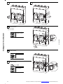
– Suitable for continuous operation at 100 % of rating only if used in a minimum cubicle space 1200 mm wide, 600 mm high and 275 mm deep.
– This switch is suitable for use on a circuit capable of delivering not more than 35 kA 1500 V DC maximum (4 poles in series) when protected by branch circuit type
fuse or circuit breaker with the same amp rating.
– For use with bus bar connection only.
– Does not provide overcurrent protection.
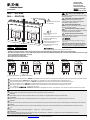
N4-4-…-S1-PV-NA
N4-4-…-S15-PV-NA
Minimum Clearance space
for all models
Blowout direction in case of
a short-circuit
Ausblasrichtung im Kurzschlussfall
Dégagement gazeux en cas
de court-circuit.
Dirección de salida de los gases
en caso de cortocircuito
Direzione di estinzione in caso
di corto circuito
Направление продувки в случае короткого замыкания
≤ 1000 V DC > 1000 V DC
a NZM4-4-XKV(I)2P(-K) b NZM4-4-XKV(I)1P(-K)
In the case of unearthed networks > 1000 VDC, the installation must be carried out in such a way as to reliably ensure that there will not be any double earth faults.
Bei ungeerdeten Netzen > 1000 V DC muss die Installation so ausgeführt sein, dass ein Doppelerdschluss ausgeschlossen ist.
Dans le cas des réseaux non mis à la terre > 1000 V DC, l'installation doit être conçue de façon à exclure un double défaut à la terre.
En redes no puestas a tierra > 1000 V DC, la instalación debe ejecutarse de forma que se excluya un cortocircuito a tierra doble.
Nelle reti non messe a terra > 1000 V DC l'installazione deve essere eseguita in modo tale da evitare un doppio guasto a terra.
对于未接地电源 > 1000 V DC,必须确保其不是双接地。
В случае незаземленных сетей > 1000 В пост. тока монтаж необходимо выполнить таким образом, чтобы исключить двойное замыкание на землю.
NOTICE
The contact surfaces of the jumpers must be blank and free from oxization. Pretreat if necessary.
ACHTUNG
Die Kontaktstellen der Brücken müssen metallisch blank, fett- und oxidfrei sein. Gegebenenfalls entsprechend vorbehandeln.
ATTENTION
Les points de contact des ponts de raccordement doivent être nus et exempts de corrosion. Effectuer un traitement préalable si nécessaire.
CUIDADO
Los puntos de contacto de los puentes tienen que ser de metal descubierto, sin grasa ni óxido. De ser necesario, deberá dárseles un tratamiento previo adecuado.
AVVISO
I punti di contatto dei ponticelli devono essere privi di residui metallici, di grasso e di ossido. Eventualmente trattarli precedentemente nel modo più consono.
注意
的接触点必须用无油脂和无氧化的裸露金属材料。如果有必要,应进行相应的预处理 .
ВНИМАНИЕ
Места контакта перемычек должы быть зачищены до металла, обезжирены и свободны от оксидной пленки. При необходимости выполнить
соответствующую предварительную обработку.
260 mm
(10.24”)
a
a
≦ 1000 V ≧ 15 mm (≧ 0.59“)
> 1000 V ≧ 70 mm (≧ 2.76“)
①
①
②
②
②
②
①
②
②
en
de
fr
es
it
zh
ru
en
de
fr
es
it
zh
ru

2/6 Emergency On Call Service: Local representative (www.eaton.eu/aftersales) or +49 (0) 180 5 223822 (de, en)
01/17 IL012055ZU
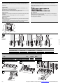
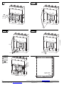
Wiring terminations molded case switch type N4-4…-S1(S15)-PV-NA
NOTICE
The removal or exchange of parts during mounting may become necessary.
Refer to installation instructions for proper assembly and to maintain electrical
clearances.
AVVISO
Per l’esecuzione degli interventi descritti potrebbe essere necessaria la
rimozione o sostituzione di alcuni pezzi.
Attenersi alle istruzioni d’installazione per garantire dopo l’assemblaggio le vie
di dispersione necessarie.
ACHTUNG
Für die Durchführung der beschriebenen Arbeiten kann das Entfernen oder
der Austausch von Teilen notwendig sein.
Bitte alle Installations-Anweisungen beachten, um die erforderlichen Luft- und
Kriechstrecken nach dem Zusammenbau zu gewährleisten.
注意
ATTENTION
L’enlèvement où l’échange de certaines pièces pendant le montage est parfois
nécessaire.
Consultez l’instruction d’assemblage pour assurer une installation
conforme aux normes.
ВНИМАНИЕ
При проведении описанных процедур может возникнуть необходимость
демонтировать или заменить детали.
Для обеспечения надлежащих зазоров и вывода тока утечки, соблюдайте
все инструкции по монтажу.
CUIDADO
Con el fin de llevar a cabo los trabajos descritos, puede ser necesario eliminar
o cambiar alguna pieza.
Le rogamos tenga en cuenta todas las instrucciones de instalación para así
garantizar las líneas de fuga y efluvio necesarias tras el montaje.
M10
metric size
hardware
Connector Wire size Wire Max. Tightening-
Type 75° C A-Rating Torque
1) Bolt on 1200 50 Nm (443 lb-in)
NZM4-XKA 4 x AWG 1/0 – 500 kcmil Cu only 1200 31 Nm (275 lb-in)
2) integrated Auxiliary Terminal 1 x AWG 12 - 18 Cu only 1.2 Nm (11 lb-in)
en
it
de
zh
fr
ru
es
90˚
90˚
90˚
90˚
29 mm
(1.2”)
29 mm
(1.2”)
29 mm
(1.2”)
F 20 mm
(F 0.8”)
F 20 mm
(F 0.8”)
F
20 mm
(F 0.8”)
F
20 mm
(F 0.8”)
F 24 mm
(F 0.9”)
F
25 mm
(F 1”)
25 mm
(1”)
25 mm
(
1”)
13 mm
(0.5”)
13 mm
(0.5”)
13 mm
(0.5”)
13 mm
(0.5”)
o 10.5 mm
(o 0.4”)
o 10.5 mm
(o 0.4”)
o 10.5 mm
(o 0.4”)
o 10.5 mm
(o 0.4”)
ab c d
f 500 mm
(F 20”)
f 260 mm
(F 10.24”)
F 50 mm
(F 2”)
F
50 mm
(F 2”)
F
20 mm
(F 0.8”)
F
24 mm
F
(0.9”)
13 mm
(0.5”)
o 10.5 mm
(o 0.4”)
e
abcde
≦ (2 x) 10 x 24 x 1 mm
≦ (2 x) 10 x 0.9“ x 0.04“
≦ (2 x) 25 x 10 mm
≦ (2 x) 1“ x 0.4“
(2 x) 10 x 50 x 1mm
(2 x) 10 x 2“ x 0.04“
(2 x) 50 x 10 mm
(2 x) 2“ x 0.4“
4 x 50 - 185 mm
2
4 x AWG 0 - 350 kcmil
1
3
4
2
1
a
3
16 mm
50 Nm
(443 lb-in )
a
15 F a < 19 mm
(0.6” F a < 0.75”)
f 260 mm
(f 10.24”)
f 32 mm
(f 1.3”)
15 F a < 19 mm
(0.6” F a < 0.75”)
1
2
M10 x 50

Emergency On Call Service: Local representative (www.eaton.eu/aftersales) or +49 (0) 180 5 223822 (de, en) 3/6
01/17 IL012055ZU
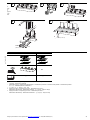
a Basic device – Grundgerät – Appareil de base – Aparato base – Apparecchio base –
基础设备 – Основное устройство
+ Combination options – Kombinationsmöglichkeiten – Combinaisons possibles – Combinaciones posibles – Combinazioni possibili –
组合方法 – Комбинационные возможности
* or – oder – ou – ó – oppure – 或者 – или
↓ Supply from above – Einspeisung von oben – Alimentation par le haut –
Alimentación desde arriba– Alimentazione dall'alto – 由上部供给 – Подача сверху
↑ Supply from below – Einspeisung von unten – Alimentation par le bas –
Alimentación desde abajo – Alimentazione dal basso – 由下部供给 – Подача снизу
or
oder
ou
ó
oppure
或者
или
≤ 1000 V > 1000 V
↓①
N/A
↑
①①
1
2
3
1
4
f 32 mm
(f 1.3”)
3
16 mm
50 Nm
(443 lb-in )
f 32 mm
(f 1.3”)
10 mm
(0.39”)
f 0.5 m
(f 1.64 ft)
M10 x 60
30 mm
(1.18”)
5
Z 2
2 Nm (17.7 lb-in)
f 18 mm
(f 0.7”)

Einklappseite: 17 mm Beschnitt
Emergency On Call Service: Local representative (www.eaton.eu/aftersales) or +49 (0) 180 5 223822 (de, en) 4/6
01/17 IL012055ZU
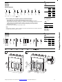
M22-K10
M22-K01
M22-CK10
M22-CK01
Auxiliary Switches
IEC
HIA HIA HIN HIN HIN
b or – oder – ou – ó – oppure – – или
Notes on mounting and wiring Auxiliary Switches for UL/CSA labeled models:
– M22-K(10)(01) have screw terminals. M22-CK(10)(01) have clamp terminals.
– Switch modules are snapped into place at the locations shown in the diagrams that follow.
– Switches will function as either „standard“ or „trip/alarm“ contacts depending on their mounting location.
– Location „HIN“ refers to standard operation. Location „HIA“ refers to „trip/alarm“ operation.
– Follow the numbering and wiring scheme provided above depending on the contact location
and function. (N.O. or N.C.)
Permissible contact configuration: 2 x HIA and/or 3 x HIN.
Note:
After mounting of the M22… switch is complete, check off the appropriate box on the auxiliary switch label
provided on the side of the breaker or switch.
-NA, -CNA (UL/CSA)
M22-CK11
M22-CK20
M22-CK02
IEC
HIA HIN
M22-CK11 M22-CK11
M22-CK20 M22-CK20
M22-CK02 M22-CK02
Mounting – Montage – Montage – Montaje – Montaggio – 安装 – Монтаж
I
th
= I
e
U
e
(V) I
e
(A)
AC-15 115 4
230 4
400 2
500 1
DC-13 24 3
42 1.7
60 1.2
110 0.6
220 0.3
4.14 4.12
4.13 4.11
a
4.24 4.22
4.23 4.21
a
1.14 1.12
1.13 1.11
a
1.24
1.22
1.23
1.21
a
1.34
1.32
1.33
1.31
a
I
th
= I
e
Pilot Duty Ratings:
B 600, Q 300
Above 300 VAC
Same polarity
U
e
(V) I
e
(A)
600 AC 5
250 DC 1
I
th
= I
e
U
e
(V) I
e
(A)
AC-15 115 4
230 4
DC-13 24 3
42 1
60 0.8
110 0.5
220 0.2
4.14 4.44
4.13 4.43
…
4.12 4.42
4.11 4.41
…
1.14 1.64
1.13 1.63
…
1.12 1.62
1.11 1.61
…
en
de
fr
es
it
zh
ru
1
OFF
2
Z 2
1
1
2
3
2
3

Einklappseite: 17 mm Beschnitt
5/6 Emergency On Call Service: Local representative (www.eaton.eu/aftersales) or +49 (0) 180 5 223822 (de, en)
01/17 IL012055ZU
M22-K10, M22-K01
(Screw Terminals)
…K10: N. O. Contact
…K01: N. C. Contact
M22-CK10, M22-CK01
(Clamp Terminals)
M22-CK11, M22-CK20, M22-CK02
(Clamp Terminals)
3
4
HIA
HIA
HIN
HIN
HIN
5a
6 - 10 mm
(0.24 - 0.39”)
2
Z 2
1 Nm (9 lb-in)
1
3
2 x 0.75 - 2.5 mm
2
2 x AWG 18 - AWG 14
5b
2 x 0.75 - 2.5 mm
2
2 x AWG 18 - AWG 14
0. 6 X 3. 5
2
1
3
2
3
1
5c
a = 8 mm
(a = 0.31“)
1 x 0.5 - 1.5 mm
2
2 x 0.5 - 0.75 mm
2
a

6/6 Emergency On Call Service: Local representative (www.eaton.eu/aftersales) or +49 (0) 180 5 223822 (de, en)
01/17 IL012055ZU
Eaton Industries GmbH, Hein-Moeller-Straße 7-11, 53115 Bonn, Germany
© 2014 by Eaton Industries GmbH, www.eaton.eu/documentation
All Rights Reserved
01/17 IL012055ZU 12316043/DE17 Doku
Printed in Germany (01/17)
Dismounting
Demontage
Démontage
Desmontaje
Smontaggio
拆卸
Демонтаж
6
TEST 1
Z 2
1 Nm
(9 lb-in)
1
3
2
ON
OFF
TEST 2
TEST 3
push to trip
tripped
3 mm
OFF
(= RESET)
en
de
fr
es
it
zh
ru
HIA
HIA
HIN
HIN
HIN
3 mm
1
2
3
140 mm
(5.5”)
180 mm
(7.1”)
4 x M5 x 110/25
2 Nm (17.7 lb-in)
-
 1
1
-
 2
2
-
 3
3
-
 4
4
-
 5
5
-
 6
6


Eaton N4-4-S1-PV-NA Series Bedienungsanleitung
- Typ
- Bedienungsanleitung
- Dieses Handbuch eignet sich auch für
in anderen Sprachen
Verwandte Artikel
-
Eaton NZM4-4-XKV2P Serie Bedienungsanleitung
-
Eaton NZM2-4-XKVI2P1P-K Instruction Leaflet
-
-
-
-
-
-
-
-