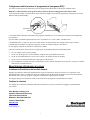
Rockwell Automation 1609-P5000E Benutzerhandbuch
- Typ
- Benutzerhandbuch

41063-257-01 (1) 990-2698 09/2005
Allen-Bradley
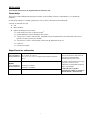
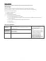
Quick Start Guide for 3000/5000 VA UPS
Schnellstartanleitung für 3000/5000 VA USV
Guide de démarrage rapide pour onduleurs 3000/5000 VA
Guía de inicio rápido para SAI de 3000/5000 VA
Guida introduttiva per gruppi di continuità da 3000/5000 VA
Guia de Início Rápido para a UPS 3000/5000 VA
1609-P3000N 3000 VA 120 VAC
1609-P3000H
3000 VA 208 VAC
1609-P3000A 3000 VA 230 VAC
1609-P5000E 5000 VA 208/230 VAC
Tower/Rack-Mount 3U Uninterruptible Power Supply
Tower/Rackmount 3HE Unterbrechungsfreie Stromversorgung (USV)
Onduleur triple monté en tour ou en baie
Sistema de alimentación ininterrumpida de 3U para montaje en torre y bastidor
Montaggio a rack/torretta 3U Gruppo di continuità
3U para Instalação em Torre/Rack Fornecimento de Corrente Ininterrupto
Installation and Operation
Installation und Betrieb
Installation et fonctionnement
Instalación y funcionamiento
Installazione e funzionamento
Instalação e operação

1
INSTALLATION
Read the Safety Instruction sheet before installing the UPS.
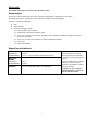
Unpacking
Inspect the UPS upon receipt. Notify the carrier and dealer if there is damage.
The packaging is recyclable; save it for reuse or dispose of it properly.
Check the package contents:
UPS
Front bezel
Literature kit containing:
PowerChute
®
Business Edition CD
Bulletin 1609-P Series User Manual CD
1609-P5000E models only: 1609-NMC (Network Management Card installed in slot located in rear of unit)
1609-P5000E models only: Network Management Card CD
Serial cable
Quick Start Guide
Environmental Specifications
TEMPERATURE
O
PERATING
S
TORAGE
32° to 104° F (0° to 40° C)
5° to 113° F (-15 to 45° C) charge UPS battery every six months
MAXIMUM
ELEVATION
O
PERATING
S
TORAGE
10,000 ft (3,000 m)
50,000 ft (15,000 m)
HUMIDITY
0% to 95% relative humidity, non-condensing
This unit is designed for indoor use
only. Select a location sturdy enough to
handle the weight.
Do not operate the UPS where there is
excessive dust or the temperature and
humidity are outside the specified limits.
Ensure the air vents on the front and
rear of the UPS are not blocked.

2
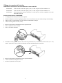
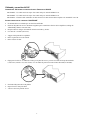
Wiring and Connecting the UPS
CONNECTING UPS USING POWER CORD: 3000VA UNITS
1609-P3000N – Use captive 8 ft cord. NEMA L5-30 Plug is attached to this cord.
1609-P3000H – Use in captive 8 ft cord. NEMA L6-30 Plug is attached to this cord.
1609-P3000A – User must supply power cord. Power cord must mate with IEC 320 C20 inlet.
H
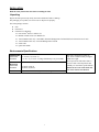
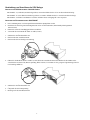
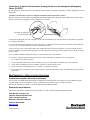
ARDWIRING INSTRUCTIONS: 1609-P5000E
• Wiring must be performed by a qualified electrician.
• Install a high magnetic 30/32 A utility circuit breaker (Allen-Bradley Catalog Number 1489-A2C300).
• Adhere to all national and local electrical codes.
• Use #10 AWG gauge (5 sq. mm) wire.
1. Switch the utility circuit breaker OFF.
2. Remove the input access panel.
3. Remove circular knockout.
4. Run #10 AWG gauge (5 sq. mm) wire through the access panel, and connect the wires to the terminal block
(Green: Ground, Brown: Hot, Blue: Neutral). Use an appropriate strain relief (not included).
5. Switch the utility circuit breaker ON.
6. Check line voltages.
7. Replace the access panel.

3
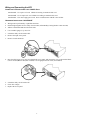
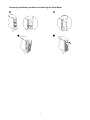
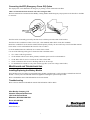
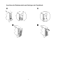
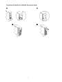
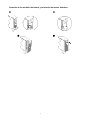
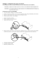
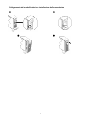
Connecting the Battery modules and Attaching the Front Bezel

4
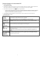
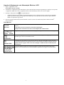
Connecting Equipment and Power to the UPS
1. Connect equipment to the UPS.
Avoid using extension cords.
2. Turn on all connected equipment. To use the UPS as a master ON/OFF switch, ensure all connected equipment is switched
ON. The equipment will not be powered until the UPS is turned on.
3. To power up the UPS press the
button on the front panel.
• The UPS battery charges when it is connected to utility power. The battery charges to 90% capacity during the first
three hours of normal operation. Do not expect full battery run capability during this initial charge period.
4. For additional computer system security, install PowerChute
®
Business Edition Smart-UPS monitoring software.
B
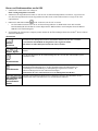
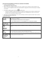
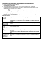
ASIC CONNECTORS
serial com
Power management software and interface cable can be used with the UPS.
Use only a supplied or approved interface cable.
Any other serial interface cable will be incompatible with the UPS connector.
normal bypass
Manual bypass enables the user to manually put connected equipment into bypass mode.
EPO terminal
Emergency Power Off terminal allows the user to connect the UPS to the central EPO system.
TVSS screw
The UPS features a transient voltage surge-suppression (TVSS) screw for connecting the ground lead
on surge suppression devices such as telephone and network line protectors.
When connecting grounding cable, disconnect the unit from the utility power outlet.
external battery
pack connector
Optional external battery packs provide extended runtime during power outages. These units support
up to ten external battery packs.

5
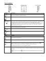
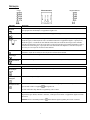
OPERATION
Load
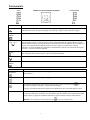
FRONT DISPLAY
Battery Charge
Indicator Description
Online
The Online LED illuminates when the UPS is drawing utility power and performing double conversion to
supply power to connected equipment.
On Battery
The UPS is supplying battery power to the connected equipment.
Bypass
The Bypass LED illuminates indicating that the UPS is in bypass mode. Utility power is sent directly to
connected equipment during bypass mode operation. Bypass mode operation is the result of an internal
UPS fault, an overload condition or a user initiated command either through an accessory or the manual
bypass switch. Battery operation is not available while the UPS is in bypass mode. Refer to
Troubleshooting in this manual.
Fault
The UPS detects an internal fault.
Refer to Troubleshooting in this manual.
Overload
An overload condition exists. See Troubleshooting.
Replace Battery
The battery is disconnected or must be replaced. See Troubleshooting.
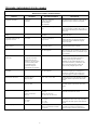
Feature Function
Power On
Press this button to turn on the UPS. (See below for additional capabilities.)
Power Off
Press this button to turn off the UPS.
Cold Start
When there is no utility power and the UPS is off, press and hold the
button to power up the UPS and
connected equipment.
The UPS will emit two beeps. During the second beep, release the button.
Self-Test
Automatic: The UPS performs a self-test automatically when turned on, and every two weeks thereafter
(by default). During the self-test, the UPS briefly operates the connected equipment on battery.
Manual: Press and hold the
button for a few seconds to initiate the self-test.

6
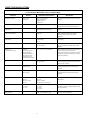
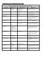
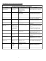
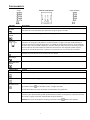
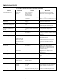
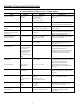
USER CONFIGURABLE ITEMS
NOTE: SETTINGS ARE MADE THROUGH SUPPLIED POWERCHUTE SOFTWARE,
OPTIONAL NETWORK MANAGEMENT CARDS, OR TERMINAL MODE.
FUNCTION
F
ACTORY
D
EFAULT
USER SELECTABLE CHOICES DESCRIPTION
Automatic Self-Test Every 14 days
(336 hours)
Every 7 days(168 hours),
14 days (336 hours)
On Startup Only,
No Self-Test
Set the interval at which the UPS will execute a
self-test.
UPS ID UPS_IDEN Up to eight characters to define the UPS Uniquely identify the UPS, (i.e. server name or
location) for network management purposes.
Date of Last Battery
Replacement
Manufacture Date Date of
Battery Replacement mm/dd/yy
Reset this date when you replace the battery
modules.
Minimum Capacity Before
Return from Shutdown
0 percent 0, 15, 25, 35, 50, 60, 75,
90 percent
Following a low-battery shutdown, the battery
modules will be charged to the specified
percentage before powering connected
equipment.
Alarm Delay After
Line Failure
5 second delay 5 or 30 second delay
At Low Battery
Never
Mute ongoing alarms or disable all alarms
permanently.
Shutdown Delay 20 seconds 0, 20, 60, 120, 240, 480,
720, 960 seconds
Set the interval between the time when the UPS
receives a shutdown command and the actual
shutdown.
Duration of
Low Battery Warning
2 minutes
PowerChute software
provides automatic,
unattended shutdown
when approximately
2 minutes of battery
operated runtime remains.
2, 5, 7, 10, 12, 15, 18, 20 minutes The low battery warning beeps are continuous
when two minutes of run time remain.
Change the warning interval default to a higher
setting if the operating system requires a longer
interval for shutdown.
Synchronized Turn-on Delay 0 seconds 0, 20, 60, 120, 240, 480,
720, 960 seconds
The UPS will wait the specified time after the
return of utility power before turn-on (to avoid
branch circuit overload).
High Bypass Point
+10% of output
voltage setting
+5%, +10%, +15%, +20% Maximum voltage that the UPS will pass to
connected equipment during internal bypass
operation.
Low Bypass Point -30% of output
voltage setting
-15%, -20%, -25%, -30% Minimum voltage that the UPS will pass to
connected equipment during internal bypass
operation.
Output Voltage 3 kVA 120 V models:
120 VAC
208/230 V models:
230 VAC
3 kVA 120 V models:
120 VAC
208/230 V models:
200, 208, 220, 230, 240 VAC
Allows the user to select the UPS output voltage
while online.
Output Frequency Automatic
50 ± 3 Hz or
60 ± 3 Hz
50 ± 3 Hz
50 ± 0.1 Hz
60 ± 3 Hz
60 ± 0.1 Hz
Sets the allowable UPS output frequency.
Whenever possible, the output frequency tracks
the input frequency.
Number of
Battery Packs
1 Number of Connected Internal Battery
Packs, (two modules per pack)
Defines the number of connected battery packs
for proper run time prediction.

7
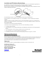
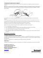
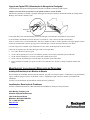
Connecting the EPO (Emergency Power Off) Option
The output power can be disabled in an emergency by closing a switch connected to the EPO.
Adhere to National and local electrical codes when wiring the EPO.
Rockwell Automation recommends Allen-Bradley Catalog Number 800F Emergency Stop Operator as the interface to the EPO
to connector.
The EPO switch is internally powered by the UPS for use with non-powered switch circuit breakers.
The EPO circuit is considered a Class 2 circuit, (UL, CSA standards) and a SELV circuit (IEC standard).
Both Class 2 and SELV circuits must be isolated from all primary circuitry. Do not connect any circuit to the EPO terminal
block unless it can be confirmed that the circuit is Class 2 or SELV.
If circuit standard cannot be confirmed, use a contact closure switch.
Use one of the following cable types to connect the UPS to the EPO switch:
• CL2: Class 2 cable for general use
• CL2P: Plenum cable for use in ducts, plenums, and other spaces used for environmental air.
• CL2R: Riser cable for use in a vertical run in a floor to floor shaft.
• CLEX: Limited use cable for use in dwellings and for use in raceways.
• For installation in Canada: Use only CSA certified, type ELC (extra-low voltage control cable).
MAINTENANCE AND TROUBLESHOOTING
Installing/Replacing the Battery Module
This UPS has an easy-to-replace, hot swappable battery module. Replacement is a safe procedure, isolated from electrical
hazards. You may leave the UPS and connected equipment on during the replacement procedure.
Refer to the Bulletin 1609-P UPS Information CD for more details.
Troubleshooting
Refer to the user manual on the Bulletin 1609-P UPS Information CD for details.
Allen-Bradley Company, LLC
Industrial Components Business
1201 South Second Street
Milwaukee, WI 53204-2496 USA
Phone 440.646.5800
www.ab.com
41063-257-01 (1)

41063-257-01 (1) 990-2698 09/2005
Allen-Bradley
Schnellstartanleitung für
3000/5000 VA USV
1609-P3000N 3000 VA 120 VAC
1609-P3000H
3000 VA 208 VAC
1609-P3000A 3000 VA 230 VAC
1609-P5000E 5000 VA 208/230 VAC
Tower/Rackmount 3HE
Unterbrechungsfreie Stromversorgung (USV)
Installation und Betrieb

1
INSTALLATION
Vor dem Installieren der USV die Sicherheitshinweise lesen.
Auspacken
Überprüfen Sie die USV nach Erhalt. Sollten Sie Schäden feststellen, benachrichtigen Sie bitte Ihren Spediteur und Händler.
Die Verpackung ist wiederverwertbar; bewahren Sie sie zur Wiederverwendung auf oder entsorgen Sie sie umweltgerecht.
Überprüfen Sie den Packungsinhalt:
USV
Frontblende
Handbuch-Set, bestehend aus:
PowerChute
®
Business Edition CD
Bulletin 1609-P Serie Benutzerhandbuch-CD
Nur für Modelle 1609-P5000E: 1609-NMC (Netzwerk-Management-Karte in Steckplatz an der Rückseite des
Geräts eingebaut)
Nur für Modelle 1609-P5000E: CD für die Netzwerk-Management-Karte
Serielles Kabel
Schnellstarthandbuch
Umgebungsspezifikationen
TEMPERATUR
B
ETRIEB
L
AGERUNG
32° bis 104° F (0° bis 40° C)
5° bis 113° F (-15 bis 45° C) USV-Batterie alle sechs Monate
aufladen
MAXIMALE
HÖHE Ü. NN
B
ETRIEB
L
AGERUNG
3.000 m (10.000 Fuß)
15.000 m (50.000 Fuß)
FEUCHTIGKEIT
0 bis 95% relative Feuchtigkeit, nichtkondensierend
Dieses Gerät ist ausschließlich zur
Verwendung in Innenräumen
vorgesehen. Wählen Sie einen
Installationsort, der das Gewicht des
Geräts aushält.
Verwenden Sie die USV nicht in einer
sehr staubigen Umgebung oder bei
Temperatur- und
Feuchtigkeitsbedingungen außerhalb der
angegebenen Grenzwerte.
Stellen Sie sicher, dass die
Luftschlitze an der Vorder- und
Rückseite der USV-Anlage nicht
blockiert sind.

2
Verdrahtung und Anschluss der USV-Anlage
ANSCHLUSS DES USV-NETZKABELS: 3000-VA-GERÄTE
1609-P3000N – 2,4-m-Kabel (mechanisch gesichert) verwenden. NEMA-Stecker L5-30 an diesem Kabel befestigt.
1609-P3000H – In 2,4-m-Kabel (mechanisch gesichert) verwenden. NEMA-Stecker L6-30 an diesem Kabel befestigt.
1609-P3000A – Netzkabel vom Benutzer zu stellen. Netzkabel muss zu Eingang IEC 320 C20 passen.
A
NLEITUNG ZUR FESTVERDRAHTUNG: 1609-P5000E
• Die Verdrahtung muss von einem qualifizierten Elektriker durchgeführt werden.
• Installieren Sie netzseitig einen hochmagnetischen 30/32-A-Überlastschalter (Allen-Bradley Katalognummer
1489-A2C300).
• Halten Sie sich an die einschlägigen Elektrovorschriften.
• Verwenden Sie einen Draht der Stärke 10 AWG (5 mm
2
).
1. Schalten Sie den Überlastschalter aus.
2. Entfernen Sie das Anschlusselement.
3. Entfernen Sie die kreisförmige Ausstanzung.
4. Führen Sie den Draht der Stärke 10 AWG (5 mm
2
) durch das Anschlusselement und schließen Sie die Drähte an der
Verteilerleiste an (Grün: Erde, Braun: Spannung, Blau: Neutral). Verwenden Sie eine geeignete Zugentlastung (nicht im
Lieferumfang enthalten).
5. Schalten Sie den Überlastschalter ein.
6. Überprüfen Sie die Nennspannung.
7. Befestigen Sie das Anschlusselement.

3
Anschluss der Batteriemodule und Anbringen der Frontblende

4
Strom- und Geräteanschluss an die USV
1. Schließen Sie Geräte an die USV-Anlage an.
Keine Verlängerungskabel verwenden.
2. Schalten Sie alle angeschlossenen Geräte ein. Um die USV als EIN/AUS-Hauptschalter zu benutzen, vergewissern Sie
sich, dass alle angeschlossenen Geräte eingeschaltet sind. Die Geräte werden nicht mit Strom versorgt, bis die USV
eingeschaltet ist.
3. Drücken Sie danach den Schalter
an der Vorderseite, um die USV zu starten.
• Die USV-Batterie lädt sich auf, wenn sie an Netzstrom angeschlossen ist. Während der ersten drei normalen
Betriebsstunden lädt sich die Batterie auf 90% Kapazität auf. Während dieser ersten Ladephase liefert die Batterie
nicht die volle Überbrückungszeit.
4. Zur Erhöhung der Sicherheit bei Computersystemen können Sie die Überwachungssoftware PowerChute
®
Business Edition
Smart-UPS installieren.
ANSCHLÜSSE
Serieller
Anschluss
Sie können Power Management-Software und Schnittstellenkabel mit der USV verwenden.
Verwenden Sie ausschließlich das mitgelieferte oder zugelassene Kabel.
Alle anderen seriellen Kabel passen nicht zum USV-Anschluss.
Normal Bypass
Im manuellen Bypass-Betrieb kann der Benutzer die angeschlossenen Geräte in den Bypass-Modus
schalten.
EPO-
Anschlussleiste
Über die Anschlussleiste für die Notabschaltung kann die USV mit dem zentralen EPO-System
verbunden werden.
TVSS-Schraube
Die USV verfügt über eine Schraube (TVSS), die Transientenschutz mit
Stoßspannungsunterdrückung bietet. An diese Schraube können die Erdungskabel von
Vorrichtungen zur Unterdrückung von Stoßspannungen angeschlossen werden, z. B.
Schutzvorrichtungen für Telefon- und Netzwerkleitungen.
Entfernen Sie die USV vom Netzstrom, bevor Sie Erdungskabel anschließen.
Anschluss für
externe Batterie-
Einheit
Optionale externe Batterie-Einheiten bieten verlängerte Laufzeit bei Stromausfällen. Die hier
beschriebenen Geräte unterstützen bis zu 10 externe Batterie-Einheiten.

5
BETRIEB
Last
FRONT-DISPLAY
Batteriekapazität
Anzeige Beschreibung
Online
Die Online-LED leuchtet auf, wenn die USV angeschlossene Geräte mit Netzstrom versorgt.
Batteriestrom
Die USV versorgt die angeschlossenen Geräte mit Batteriestrom.
Bypass
Die Bypass-LED zeigt an, dass sich die USV im Bypass-Modus befindet. In diesem Modus wird
Netzstrom direkt an die angeschlossenen Geräte weitergegeben. Die USV kann sich aufgrund eines
internen USV-Fehlers, einer Überlastung oder eines per Zubehörkomponente bzw. über den manuellen
Bypass-Schalter eingegebenen Befehls in den Bypass-Modus schalten. In diesem Modus ist kein
Batteriebetrieb möglich. Siehe Fehlersuche weiter hinten in diesem Handbuch.
Fehler
Die USV hat einen internen Fehler erkannt.
Siehe Fehlersuche weiter hinten in diesem Handbuch.
Überlast
USV ist überlastet. Siehe Fehlersuche weiter hinten in diesem Handbuch.
Batterie ersetzen
Die Batterie ist nicht angeschlossen oder muss ersetzt werden. Siehe Fehlersuche weiter hinten in diesem
Handbuch.
Funktion Beschreibung
Einschalter
Diese Taste drücken, um die USV einzuschalten. (Weitere Funktionen sind in den nachfolgenden
Abschnitten beschrieben.)
Ausschalter
Diese Taste drücken, um die USV auszuschalten.
Kaltstart
Ist kein Netzstrom vorhanden, und die USV ist ausgeschaltet, halten Sie die Taste
gedrückt, um die
USV und angeschlossene Geräte einzuschalten.
Die USV gibt zwei Pieptöne von sich. Lassen Sie die Taste während des zweiten Pieptons los.
Selbsttest
Automatisch: Die USV führt zuerst automatisch einen Selbsttest durch, wenn sie eingeschaltet wird, und
danach alle zwei Wochen (Standard). Während des Selbsttests laufen die angeschlossenen Geräte für
kurze Zeit mit Batteriestrom.
Manuell: Die Taste
einige Sekunden lang gedrückt halten, um den Selbsttest zu starten.

6
VOM BENUTZER KONFIGURIERBARE EINSTELLUNGEN
HINWEIS: EINSTELLUNGEN WERDEN ÜBER DIE BEILIEGENDE POWERCHUTE-SOFTWARE,
OPTIONALE NETZWERK-MANAGEMENT-KARTEN ODER IM TERMINALMODUS VORGENOMMEN.
BESCHREIBUNG
S
TANDARD-
E
INSTELLUNG
BENUTZEROPTIONEN BESCHREIBUNG
Automatischer Selbsttest Alle 14 Tage
(336 Stunden)
Alle 7 Tage (168 Stunden),
14 Tage (336 Stunden)
Nur beim Starten,
Kein Selbsttest
Bestimmen Sie die Intervalle, in denen die USV
einen Selbsttest durchführen soll.
USV-ID UPS_IDEN Bis zu acht Zeichen, um die USV zu
kennzeichnen
Weisen Sie der USV einen Namen zu (z. B.
Servername oder Standort), um sie im Netzwerk
leichter auffinden zu können.
Datum des letzten
Batterieaustauschs
Herstellungsdatum Datum des Batteriewechsels
MM/TT/JJ
Setzen Sie dieses Datum zurück, wenn Sie die
Batteriemodule auswechseln.
Mindestkapazität vor
Wiedereinschalten
0 Prozent 0, 15, 25, 35, 50, 60, 75,
90 Prozent
Nach einer Abschaltung wegen einer erschöpften
Batterie werden die Batteriemodule bis zum
festgelegten Ladeprozentsatz aufgeladen, bevor
angeschlossene Geräte wieder mit Strom
versorgt werden.
Alarmverzögerung nach
Stromausfall
5 Sekunden Verzögerung 5 oder 30 Sekunden Verzögerung
Bei schwacher Batterie
Nie
Hiermit schalten Sie aktive Alarme aus oder
deaktivieren alle Alarme vollständig.
Abschaltverzögerung 20 Sekunden 0, 20, 60, 120, 240, 480,
720, 960 Sekunden
Hiermit bestimmen Sie, wann das eigentliche
Herunterfahren durchgeführt wird, nachdem die
USV den Befehl zum Herunterfahren erhalten
hat.
Warndauer bei niedriger
Batteriekapazität
2 Minuten
PowerChute verfügt über
eine automatische
Abschaltfunktion, die
aktiviert wird, wenn noch
2 Minuten Batterielaufzeit
verbleiben.
2, 5, 7, 10, 12, 15, 18, 20 Minuten Der Batterie-Alarm ertönt durchgehend, wenn
noch etwa 2 Minuten Laufzeit verbleiben.
Erhöhen Sie die Warndauer, wenn die
angeschlossenen Geräte längere zum Abschalten
benötigen.
Synchronisierte
Einschaltverzögerung
0 Sekunden 0, 20, 60, 120, 240, 480,
720, 960 Sekunden
Hier wartet die USV die angegebene Zeit, bevor
sie sich wieder einschaltet, nachdem die
Eingangsspannung nach einem Stromausfall
wiederhergestellt wurde (z. B. um eine
Überlastung des Abzweigstromkreises zu
verhindern).
Hoher Bypass-Punkt
+10% der eingestellten
Ausgangsspannung
+5%, +10%, +15%, +20% Maximale Spannung, die die USV während des
internen Bypass-Betriebs an angeschlossene
Geräte weitergibt.
Niedriger Bypass-Punkt -30% der eingestellten
Ausgangsspannung
-15%, -20%, -25%, -30% Mindestspannung, die die USV während des
internen Bypass-Betriebs an angeschlossene
Geräte weitergibt.
Ausgangsspannung 3 kVA 120-V-Modelle:
120 VAC
208/230-V-Modelle:
230 VAC
3 kVA 120-V-Modelle:
120 VAC
208/230-V-Modelle:
200, 208, 220, 230, 240 VAC
Ermöglicht die Auswahl der USV-
Ausgangsspannung im Online-Betrieb.
Ausgangsfrequenz Automatisch
50 ± 3 Hz oder
60 ± 3 Hz
50 ± 3 Hz
50 ± 0,1 Hz
60 ± 3 Hz
60 ± 0,1 Hz
Zum Einstellen der USV-Ausgangsfrequenz. Die
Ausgangsfrequenz wird nach Möglichkeit an die
Eingangsfrequenz angeglichen.
Anzahl der
Batterie-Einheiten
1 Anzahl der angeschlossenen internen
Batterie-Einheiten, (zwei Module pro
Einheit)
Legt die Anzahl der angeschlossenen Batterie-
Einheiten für die korrekte Berechnung der
Laufzeit fest.

7
Anschließen des EPO-Schalters (Notabschaltung)
Der Ausgangsstrom kann im Notfall durch einen Schalter abgeschaltet werden, der an die EPO-Funktion angeschlossen ist.
Beachten Sie beim Verdrahten der Notabschaltung die einschlägigen Elektrovorschriften.
Rockwell Automation empfiehlt die Notaus-Steuereinheit (Allen-Bradley, Katalognummer 800F) als Schnittstelle zwischen
Notfall-Fernabschaltung und Anschluss.
Die Notabschaltung wird intern versorgt, zur Verwendung mit nicht bestromten Überlastschaltern.
Der EPO-Schaltkreis wird als Schaltkreis der Klasse 2 (UL, CSA-Standard) bzw. als SELV-Schaltkreis (IEC-Standard)
eingestuft.
Schaltkreise der Klasse 2 und SELV-Schaltkreise müssen von allen Primärschaltkreisen isoliert sein. Verbinden Sie keine
Schaltkreise mit der EPO-Anschlussleiste, wenn nicht feststeht, ob es sich um einen Schaltkreis der Klasse 2 oder um einen
SELV-Schaltkreis handelt.
Verwenden Sie im Zweifelsfall einen Kontaktschließschalter.
Verwenden Sie einen der folgenden Kabeltypen, um die USV mit der Notabschaltung zu verbinden:
• CL2: Klasse-2-Mehrzweckkabel
• CL2P: Plenumkabel zur Verwendung in Rohrleitungen, Deckenhohlräumen und anderen zur Luftversorgung genutzten
Räumen.
• CL2R: Steigleitung für vertikale Verlegung in Schächten und zwischen Stockwerken.
• CLEX: Spezialkabel zur Verwendung in Wohnungen und Kabelkanälen.
• Bei Installation in Kanada: Nur CSA-zertifizerte Niederspannungssteuerkabel vom Typ ELC verwenden.
WARTUNG UND FEHLERSUCHE
Einbau/Austausch des Batteriemoduls
Die USV verfügt über ein Batteriemodul, das ohne großen Aufwand und während des Betriebs ausgetauscht werden kann. Das
Auswechseln der Batteriemodule ist vollkommen gefahrlos und mit keinerlei Stromschlaggefahr verbunden. Sie können die
USV und alle angeschlossenen Geräte eingeschaltet lassen, während Sie das Batteriemodul auswechseln.
Weitere Einzelheiten finden Sie auf der Bulletin 1609-P USV Informations-CD.
Fehlersuche
Weitere Einzelheiten finden Sie im Benutzerhandbuch auf der Bulletin 1609-P USV Informations-CD.
Allen-Bradley Company, LLC
Industrial Components Business
1201 South Second Street
Milwaukee, WI 53204-2496, USA
Telefon +1-440-646-5800
www.ab.com
41063-257-01 (1)
EPO-Schalte
r

41063-257-01 (1) 990-2698 09/2005
Allen-Bradley
Guide de démarrage rapide
pour onduleurs 3000/5000 VA
1609-P3000N 3000 VA 120 V CA
1609-P3000H
3000 VA 208 V CA
1609-P3000A 3000 VA 230 V CA
1609-P5000E 5000 VA 208/230 V CA
Onduleur triple
monté en tour ou en baie
Installation et fonctionnement

1
INSTALLATION
Veuillez lire la fiche de sécurité avant d'installer l'onduleur.
Déballage
Inspectez l’onduleur dès sa réception. Informez le transporteur et le revendeur si vous constatez des dommages.
L’emballage est recyclable ; conservez-le donc pour réemploi ou jetez-le conformément au respect de l'environnement.
Vérifiez le contenu du paquet :
Onduleur
Panneau avant
Kit de documentation contenant :
CD PowerChute
®
Business Edition
CD du guide d'utilisation des onduleurs de la série Bulletin 1609-P
Modèles 1609-P5000E uniquement : carte de gestion réseau 1609-NMC (installée sur l'emplacement situé à
l'arrière de l'unité)
Modèles 1609-P5000E uniquement : CD de la carte de gestion de réseau
Câble série
Guide de démarrage rapide
Caractéristiques environnementales
TEMPERATURE
F
ONCTIONNEMENT
E
NTREPOSAGE
32° à 104° F (0° à 40° C)
5° à 113° F (-15° à 45° C) Recharger la batterie de l'onduleur
tous les six mois
ALTITUDE
MAXIMUM
F
ONCTIONNEMENT
E
NTREPOSAGE
10 000 pieds (3 000 m)
50 000 pieds (15 000 m)
HUMIDITE
0 à 95 % d'humidité relative, sans condensation
Cette unité est conçue uniquement pour
un usage intérieur. Sélectionnez un
endroit assez stable et solide pour son
poids.
Évitez d’utiliser l'onduleur dans un
environnement excessivement
poussiéreux ou hors des limites de
température et d’humidité spécifiées.
Assurez-vous que les fentes
d’aération à l’avant et à l’arrière de
l’onduleur ne sont pas bloquées.

2
Câblage et connexion de l'onduleur
CONNEXION DE L'ONDULEUR PAR CABLE D'ALIMENTATION : UNITES A 3000 VA
1609-P3000N – Utiliser le câble encastré de 8 pieds (2,5 m). Ce câble comporte une fiche NEMA L5-30.
1609-P3000N – Utiliser le câble encastré de 8 pieds (2,5 m). Ce câble comporte une fiche NEMA L6-30.
1609-P3000A – Câble d'alimentation fourni par l'utilisateur. Ce câble doit avoir une fiche compatible avec la prise
d'entrée IEC 320 C20.
I
NSTRUCTIONS DE CABLAGE : 1609-P5000E
• Le câblage doit être réalisé par un électricien qualifié.
• Installez un disjoncteur secteur magnétique primaire à 30/32 A (référence 1489-A2C300 du catalogue Allen-Bradley).
• Observez tous les codes nationaux et locaux relatifs aux installations électriques.
• Utilisez un fil de gabarit 10 AWG (5 mm
2
).
1. Mettez le disjoncteur de l'alimentation secteur en position Arrêt.
2. Enlevez le panneau d’accès d’entrée.
3. Enlevez la rondelle détachable.
4. Introduisez le fil de gabarit 10 AWG (5 mm
2
) à travers le panneau d’accès, et connectez les fils aux bornes (vert : terre,
marron : phase, bleu : neutre). Utilisez un réducteur de tension de câble approprié (non inclus).
5. Mettez le disjoncteur de l'alimentation secteur en position Marche.
6. Vérifiez les tensions de la ligne de secteur.
7. Remettez le panneau d’accès en place.

3
Connexion des batteries et fixation du panneau avant
Seite wird geladen ...
Seite wird geladen ...
Seite wird geladen ...
Seite wird geladen ...
Seite wird geladen ...
Seite wird geladen ...
Seite wird geladen ...
Seite wird geladen ...
Seite wird geladen ...
Seite wird geladen ...
Seite wird geladen ...
Seite wird geladen ...
Seite wird geladen ...
Seite wird geladen ...
Seite wird geladen ...
Seite wird geladen ...
Seite wird geladen ...
Seite wird geladen ...
Seite wird geladen ...
Seite wird geladen ...
Seite wird geladen ...
Seite wird geladen ...
Seite wird geladen ...
Seite wird geladen ...
Seite wird geladen ...
Seite wird geladen ...
Seite wird geladen ...
Seite wird geladen ...
-
 1
1
-
 2
2
-
 3
3
-
 4
4
-
 5
5
-
 6
6
-
 7
7
-
 8
8
-
 9
9
-
 10
10
-
 11
11
-
 12
12
-
 13
13
-
 14
14
-
 15
15
-
 16
16
-
 17
17
-
 18
18
-
 19
19
-
 20
20
-
 21
21
-
 22
22
-
 23
23
-
 24
24
-
 25
25
-
 26
26
-
 27
27
-
 28
28
-
 29
29
-
 30
30
-
 31
31
-
 32
32
-
 33
33
-
 34
34
-
 35
35
-
 36
36
-
 37
37
-
 38
38
-
 39
39
-
 40
40
-
 41
41
-
 42
42
-
 43
43
-
 44
44
-
 45
45
-
 46
46
-
 47
47
-
 48
48


Rockwell Automation 1609-P5000E Benutzerhandbuch
- Typ
- Benutzerhandbuch
in anderen Sprachen
Verwandte Artikel

Andere Dokumente
-
 Allen-Bradley 1609-P10000E Benutzerhandbuch
-
Bay Networks BayStack UPS45 Quick Reference Manual
-
Fortress Technologies AS/400 Installation and Service Manual
-
Schneider Electric Easy UPS On-Line Bedienungsanleitung
-
-
-
BlueWalker PowerWalker VFI 1000 LCD Spezifikation
-
Tripp Lite Single-Phase Rackmount On-line UPS Bedienungsanleitung
-
-
BlueWalker VFI 6000R LCD Spezifikation
