
R412008306/07.2014, Replaces: 12.2005, DE/EN/FR/IT/ES/SV
Pin-Belegung für D-SUB-Anschluss
Pin Assignment for D-SUB Connection
Affectation de broches pour connecteur D-SUB
Occupazione pin per attacco D-SUB
Ocupación de pines para la conexión D-SUB
Stiftsbeläggning för D-SUB-anslutning
VS LS04
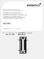
Belegungsplan | Assignment scheme | Plan d'affectation |
Schema di occupazione | Esquema de ocupación | Beläggningsschema
1
14
13
25
11 x
2 x
(7472D03924)

Deutsch
Maximalkonfiguration Ventilplatten:
11 x beidseitig betätigt, 2 x einseitig betätigt
Zu diesem Belegungsplan
Dieser Belegungsplan enthält wichtige Informationen für die sichere und
sachgerechte Herstellung der korrekten Pin-Belegung der D-SUB-Ansteuerung des
Ventilsystems LS04 mit 11 beidseitig und 2 einseitig betätigten Ventilplatten.
W Lesen Sie daher diesen Belegungsplan, bevor Sie den Gegenstecker des D-SUB-
Anschlusses konfigurieren.
W Bewahren Sie diesen Plan so auf, dass er für alle Benutzer zugänglich ist.
Mitgeltende Dokumente
W Bedienungsanleitung des VS LS04
W Technische Daten und Angaben gemäß Online-Katalog
(www.aventics.com/pneumatics-catalog)
Das müssen Sie beachten
W Benutzen Sie ein Anschlusskabel für 24 V über Trenntrafo mit Basisisolierung
nach EN 20178, Klassifikation VDE 0160.
W Verwenden Sie die Angaben dieses Plans nur zur Pin-Belegung eines
Gegensteckers für die D-SUB-Buchse des VS LS04 mit der genannten
Maximalkonfiguration.
W Beachten Sie die Angaben dieses Bedienungsplans sowie alle mitgeltenden
Dokumente und Begleitunterlagen.
W Halten Sie die nationalen Unfallverhütungsvorschriften am Einsatzort ein.
W Stellen Sie sicher, dass die Pin-Belegung des Gegensteckers nur von
qualifiziertem und geschultem Fachpersonal durchgeführt wird.
W Schalten Sie das System drucklos und spannungsfrei, bevor Sie mit Arbeiten am
VS beginnen.
Beschreibung und Einsatzbereich
Das VS LS04 verfügt über einen 25-poligen D-SUB-Anschluss an der EP-Endplatte
zur Ansteuerung der montierten Ventile.
Die Pin-Belegung dieses Anschlusses ist durch die gewählte Konfiguration
vorgegeben.
Um die korrekte Ventilansteuerung sicherzustellen, muss der Gegenstecker so
konfiguriert werden, dass jeder Pin des D-SUB-Anschlusses von der steuernden
Elektrik richtig angesteuert wird.
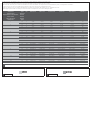
In Tab. ist die richtige Pin-Belegung des D-SUB-Anschlusses für das VS LS04 mit
der Anschlussvariante 2 dargestellt.
English
Maximum configuration for valve plates:
11x bistable, 2x mono-stable
About this assignment scheme
This assignment scheme contains important information on the safe and
appropriate establishment of the correct pin assignment for the D-SUB control of the
LS04 valve system with 11 bistable and 2 mono-stable valve plates.
W Read this assignment scheme thoroughly before configuring the mating plug of
the D-SUB connection.
W Keep this scheme in a location where it is accessible to all users.
Related documents
W VS LS04 operating instructions
W Technical data and information pursuant to the online catalog
(www.aventics.com/pneumatics-catalog)
The following must be observed
W Use a connection cable for 24 V via an isolating transformer with basic isolation
according to EN 20178, classification VDE 0160.
W Use the information in this scheme solely for the pin assignment of a mating plug
for the D-SUB bushing of the VS LS04 with the cited maximum configuration.
W Observe the information contained in this assignment scheme as well as all
related documents and accompanying documents.
W Adhere to national accident prevention regulations at the place of installation.
W Ensure that the pin assignment of the mating plug is only carried out by qualified
and trained specialists.
W Make sure the system is not under pressure or voltage before starting work on
the VS.
Vorkonfektionierte Kabel mit passendem D-SUB-Gegenstecker finden Sie im
Online-Katalog (www.aventics.com/pneumatics-catalog).
1
Description and applications
The VS LS04 has a 25-pin D-SUB connection on the EP end plate to control the
mounted valves.
The pin assignment of this connection is stipulated by the selected configuration.
To ensure correct valve control, the mating plug has to be configured in such a way
that each pin of the D-SUB connection is correctly controlled by the controlling
electronics.
The correct pin assignment of the D-SUB connection for the VS LS04 with connection
variant 2 is shown in Tab. .
Français
Configuration maximale embases de distributeurs:
11 x bistables, 2 x monostables
A propos du plan d’affectation
Ce plan comporte des informations importantes pour effectuer de manière sûre et
conforme l'affectation correcte des broches de la commande D-SUB du VS LS04
doté de 11 embases de distributeurs bistables et de 2 monostables.
W Lire donc attentivement ce plan d’affectation avant de configurer la fiche femelle
du connecteur D-SUB.
W Ranger le plan à un endroit tel que tous les utilisateurs puissent y accéder.
Autres documents applicables
W Mode d'emploi du VS LS04
W Données techniques et indications mentionnées dans le catalogue en ligne
(www.aventics.com/pneumatics-catalog)
Respecter les consignes suivantes
W Utiliser un câble de raccordement pour 24 V via un transformateur d'isolation
avec une isolation de base selon EN 20178, classification VDE 0160.
W Utiliser les indications de ce plan uniquement pour l'affectation des broches
d'une fiche femelle pour la douille D-SUB du VS LS04 avec la configuration
maximale indiquée.
W Respecter les indications de ce plan d'affectation ainsi que tous les autres
documents applicables et ceux fournis en annexe.
W Respecter les règlements de prévention des accidents sur le site d'utilisation.
W S'assurer que l'affectation des broches de la fiche femelle soit réalisée
uniquement par du personnel qualifié et formé.
W Mettre le système hors pression et hors tension avant toute opération sur le VS.
Description et domaine d'application
Le VS LS04 dispose d'un connecteur D-SUB à 25 pôles sur l'embase terminale EP
pour la commande des distributeurs montés.
L'affectation des broches de ce connecteur est déterminée par la configuration
sélectionnée.
Afin de garantir la commande correcte du distributeur, la fiche femelle doit être
configurée de telle sorte que chaque broche du connecteur D-SUB soit correctement
commandée par l'électrique de pilotage.
Le Tab. représente l'affectation correcte des broches du connecteur D-SUB pour
le VS LS04 avec la variante de raccordement 2.
Pre-assembled cables with suitable D-SUB mating plugs can be found in the
online catalog (www.aventics.com/pneumatics-catalog).
Des câbles pré-assemblés avec fiche femelle correspondante pour le
connecteur D-SUB sont présentés dans le catalogue en ligne
(www.aventics.com/pneumatics-catalog).
1
1
AVENTICS | VS LS04 | R412008306–BDL–001–AB | Deutsch/English/Français 1
Seite wird geladen ...
Seite wird geladen ...
Seite wird geladen ...
Seite wird geladen ...
-
 1
1
-
 2
2
-
 3
3
-
 4
4
-
 5
5
-
 6
6


AVENTICS Series LS04 Assembly Instructions
- Typ
- Assembly Instructions
- Dieses Handbuch eignet sich auch für
in anderen Sprachen
- English: AVENTICS Series LS04
- français: AVENTICS Series LS04
- español: AVENTICS Series LS04
- italiano: AVENTICS Series LS04
- svenska: AVENTICS Series LS04
Verwandte Artikel
-
AVENTICS Series LS04 Assembly Instructions
-
AVENTICS Series CON-MP Assembly Instructions
-
-
-
-
-