

2
Introduction
Dear
Customer,
Congratulations
on
your
purchase
of
the
world's
finest
brand
of
audio
products.
At
Rockford
Fosgate
we
are
fanatics
about
musical
reproduc
-
tion
at
its
best
,
and
we
are
pleased
you
chose
our
product.
Through
years
of
engineering
expertise
,
hand
craftsmanship
and
critical
testing
procedures,
we
have
created
a
wide
range
of
products
that
reproduce
music
with
all
the
clarity
and
richness
you
deserve.
For
maximum
performance
we
recommend
you
have
your
new
Rockford
Fosgate
product
installed
by
an
Authorized
Rockford
Fosgate
Dealer,
as
we
provide
specialized
training
through
Rockford
Technical
Training
Institute
(RTTI).
Please
read
your
warranty
and
retain
your
receipt
and
original
carton
for
possible
future
use
.
Great
product
and
competent
installations
are
only
a
piece
of
the
puzzle
when
it
comes
to
your
system.
Make
sure
that
your
installer
is
using
100%
authentic
installation
accessories
from
Rockford
Fosgate
in
your
installation.
Rockford
Fosgate
has
everything
from
RCA
cables
and
speaker
wire
to
power
wire
and
battery
connectors
.
Insist
on
it!
After
all
,
your
new
system
deserves
nothing
but
the
best.
To
add
the
finishing
touch
to
your
new
Rockford
Fosgate
image
,
order
your
Rockford
accessories
,
which
include
everything
from
T-shirts
to
hats
.
Visit
our
web
site
for
the
latest
information
on
all
Rockford
products;
www.
rockfordfosgate.
com
or
,
in
the
U.S.
call1-800-669-9899
or
FAX
1-800-398-3985
.
For
all
other
countries
,
call
+001-480-967
-3565
or
FAX
+001-480-966-3983
Table
of
Content
2
Introduction
3-5
Specifications
6-9
Installation
Installation
Considerations
Mounting
Wiring
10-11
Additional
Languages
French
Spanish
German
Italian
12
Limited
Warranty
Information
If,
after
reading
your
manual,
you
still
have
questions
regarding
this
prod-
uct
,
we
recommend
that
you
see
your
Rockford
Fosgate
dealer
.
If
you
need
further
assistance,
you
can
call
us
direct
at
1-800-669-9899
.
Be
sure
to
have
your
serial
number,
model
number
and
date
of
purchase
available
when
you
call.
Safety
This
symbol
with
"WARNING
"
is
intended
to
alert
the
user
to
the
presence
of
important
4
WARNING
instructions
.
Failure
to
heed
the
instructions
~
will
result
in
severe
injury
or
death
.
This
symbol
with
"CAUTION"
is
intended
to
alert
the
user
to
the
presence
of
important
4
CAUTION
instructions
.
Failure
to
heed
the
instructions
~
can
result
in
injury
or
unit
damage
.
•
To
prevent
injury
and
damage
to
the
unit,
please
read
and
follow
the
instructions
in
this
manual
.
We
want
you
to
enjoy
this
system,
not
get
a
headache
.
•
If
you
fee
l
unsure
about
installing
this
system
yourself
,
have
it
installed
by
a
qualified
Rockford
Fosgate
technician.
•
Before
installation,
disconnect
the
battery
negative
(-)
terminal
to
prevent
damage
to
the
unit,
fire
and/or
possible
injury
.
r~,..
2014
Fic"Krord
C'WJC'
1L1'1
A
I
~i~r·~
Resc.rvPr,
RCCt<f
CJ~C
~uS
GATE
P
JNC~
'f~l
3nd
associated
oqos
where
apolicablc
are
reg1stered
trademarks
of
Rocktorri
C,1r
pcra
1
nr
r
the
U'l
t
~,
S.a
1• •
nOt!''
Ahe
~
r r
1'
1 ;
Ad
c
','
'
l
yyl1f'\S
ar0
t
1e
prcperty
0
1
:t"J~i·
·espective
')Wners.
Spec
ficat101s
SL.b
ect
to
change
w1t'lc
1!
J.

Specifications
l,<J
"'
~
'
~'·
'
·...._
~;;.
P152-S
P16-S
P165-SE
P165-SI
P1675-S
PH-S
~
5.25"
6"
6.5" 6.5"
6.75"
1.0
"
\jl·.:··
lif
i(
;:
(133mm)
(153mm)
(165mm)
(165mm)
(171.5mm)
(25mm)
2-Way
2-Way 2-Way
2-Way
2-Way
Tweeter
ho·:~i
n2l
40
40
40 40
40
40
70-22kHz
60-22kHz
44-20kHz
43-20kHz
55-22kHz
3.5kHz-22kHz
Voice
C~
;
ii
Di
anJH
t
er
1.0
"
1.0" 1.0"
1.
0"
1.0"
1.0"
(25.4mm)
(25.4mm)
(25.4mm)
(25.4mm)
(25.4mm) (25.4mm)
SOW
I
100W
60W
I
120W
60W
I
120W
60W
I
120W
60W
I
120W
60W
I
120W
F3
-
crfe
Air
R
e
::
n
n
Jnc:~
70Hz
60Hz
59
Hz
58
Hz
60Hz
3.5
kHz
0!:
0.68
0.70 0.77 0.74
0.72
N
IA
0.19f
P
0.42
fj3
0.
56fj3
0.59
IP
0.61
fj3
NIA
(5.4L)
(11.8L)
(15.9L)
(16.7L)
(17.4L)
S
~
:ns
i
ti
v: ty
87dB
87.2dB
88dB
88dB
89dB
90dB
Sem.~tivi:
y
i'-
90dB
90
.
2dB
91dB
91dB
92dB
93dB
Xmax
0.
10"
0.
11"
0.
12"
0.12"
0.25
"
NIA
(2.5mm)
(2.8mm)
(3mm)
(3mm)
(6.4mm)
fv
1
Jufl
tlri
rJ
D!a:·r
i
t:
"nr
4.81"
5.05"
5.
51"
5.51"
5.68"
1.75
"
(122.2mm)
(128.2mm)
(140mm)
(140mm)
(144.2mm)
(44.4mm)
1.
91
" 1.
93"
2.
24
"
2.2
4" 2.
24
" 0.91"
(48.5mm)
(49
.
0mm)
(57.0mm)
(57
.
0mm)
(57.
0mm)
(
23.
1mm)
YES
YES YES
YES
YES
YES
Ad&DtJr
P!ate
YES
NO NO NO NO
NO
See
pages
4-5
for
additional
dimensions
CFA
203
1
~;
y·::tJr
Sp8tlker
has
n·;~;
I
''•
'ljl
c
·
~~
{r
~:
·
;r
~.
::
:
Jr1111
a~
i
2 vo~
ce
c
ci:s.
3

4
Specifications
P152-S
P16-5
6.
69"
(170.0mm)
Diameter
P165-5E/P165-51
6.5"
c-
----
(185mm)
P1675-5
ill
us.-1.1
5.
43"
6.
22'
~I
~
(158.
0mm)
(138.0mm)
Diameter
"!/
\S
6.10"
(155.0mm)
Diameter
5.59'
(142.0mm)
Di
ameter
6.18"
(157.0mm)
Diameter
6.1"
(156mm)
6.8
"
(
17
2mm)
1:
SJ2
Z'
6.
97'
1----
(177.0mm)
I
~
"!/
0.88'
(22.3mm)
'S
=I
0.9"
(23mm)
0.8
0'
(20.
4mm
)
I

P1T-S
0.30"
(8mm)
I
0.50"
1--
(13mm)
Surface
Mount
I _
2.13"
-1
-.I
r-
1.06"
I,
(54mm)
~
I : I
(27mm)
~
~
u
F
lush
Mount
Tweeter Crossover
P165-SE
3.35"
(8
5mm)
---------1
2.85"
------j '
(7
3m
m)
I
Tweeter Crossover
PH-S
3.35"
(85mm)
2.85"
(73mm)
r
f
1.- 0.
91
"
(2
3m
m)
3.16"
(80mm) -
--
3.
16"
..
(80mm) ---
~
~
1.
38" '
r (35mm) !
~I
-
~
~,
~~~
I
t 26"
I
r--
(32mm)
-----J
1.
38"
1
r(35mm)
_.,..
~
~
t±;~±
L
~~
)
~
~
5
~~)
~
-
_r
I
t26
" I
r-- (32mm) ---1
Specifications

6
Installation
Contents
•
(1)
Pair
Punch
Series
Full
Range
Component
Speakers
•
(1)
Pair
of
grilles/trim
rings
•
Mounting
Hardware
Installation
Considerations
Before
beginning
any
installation,
follow
these
simple
rules:
1.
Be
sure
to
carefully
read
and
understand
the
instructions
before
attempting
to
install
these
speakers.
2.
For
safety,
disconnect
the
negative
lead
from
the
battery
prior
to
beginning
the
installation.
3.
For
easier
assembly,
we
suggest
you
run
all
wires
prior
to
mounting
your
speakers
in
place.
4.
Use
high
quality
connectors
for
a
reliable
installation
and
to
minimize
signal
or
power
loss.
5.
Think
before
you
drill!
Be
careful
not
to
cut
or
drill
into
gas
tanks,
fuel
lines,
brake
or
hydraulic
lines,
vacuum
lines
or
electrical
wiring
when
working
on
any
vehicle
.
If
installation
in
a
boat,
take
care
not
to
cut
or
drill
through
the
main
hull.
6.
Never
run
wires
underneath
the
vehicle.
Running
the
wires
inside
the
vehicle
or
hull
area
provides
the
best
protection
.
7.
Avoid
running
wires
over
or
through
sharp
edges.
Use
rubber
or
plastic
grommets
to
protect
any
wires
routed
through
metal,
especially
the
firewall.
Mounting
Mid-Bass
1.
Determine
where
the
speakers
will
be
mounted
.
Ensure
an
area
large
enough
for
the
speaker
to
mount
evenly
.
Be
sure
that
the
mounting
location
is
deep
enough
for
the
speaker
to
fit;
if
mounting
in
a
door,
operate
all
functions
(windows,
locks,
etc.)
through
their
entire
operating
range
to
ensure
there
is
no
obstruction.
2.
Refer
to
the
specification
chart
to
determine
the
proper
diameter
hole
to
cut
for
your
speaker
model.
Cutting
and
mounting
templates
can
be
found
at
www.rockfordfosgate.com.
3.
Mark
the
locations
for
the
mounting
screws.
Drill
the
holes
with
a
1/8"
bit.
4.
Feed
the
speaker
wires
through
the
cutout
and
connect
to
the
speaker
terminals.
Be
sure
to
observe
proper
polarity
when
connecting
the
wires
.
The
speaker's
positive
terminal
is
indicated
with
a"+
".
5.
Fit
the
trim
ring
over
the
speaker
and
mount
into
place
using
four
(4)
screws.
6.
Tighten
the
screws
until
the
speaker
is
snug
in
place
to
prevent
rattling.
Do
not
over
tighten
the
screws.
Mounting
tab
removal
for
some
installations
0
Use
pliers
to
break
off
plastic
tab.
illus.
-2
.1
/ I
/)
Example
of
standard
door
installation
......
~~
(/:
~-
...
~9~i~i9n,~:
·
·~o
Align
Holes
..
...-
·
:
................. .
Tweeter-
Discreet
Dual
Clamp
(DOC™)
1.
Dete
r
mine
where
the
speakers
will
be
mounted.
Ensure
an
area
large
enough
for
the
speaker
to
mount
evenly.
Be
sure
that
the
mounting
location
is
deep
enough
for
the
speaker
to
fit;
if
m
ounting
in
a
door,
operate
all
functions
(windows,
locks,
etc
.) t
hrough
their
entire
operating
range
to
ensure
there
is
no
obstruction.
2.
Mark
the
location
for
the
mounting
hole.
Drill
the
hole
with
a
standard
1.75
inch
(45mm)
hole
saw
.
3.
With
a
single
center
screw
secure
the
inner
cup
fr
om
the
front
of
the
door
panel
to
the
outer
cup
fr
om
back
of
the
doo
r
panel.
Tighten
the
screw
until
balanced
pressure
is
applied
to
both
faces
of
the
mounting
surface.
4.
Feed
t
he
speaker
wires
through
the
cutout
and
connect
to
the
speaker
terminals.
Be
sure
to
observe
proper
polarity
when
connecting
the
wires.
The
speaker's
lead
wires
are
indicated
wit
h a
RED
wire
"+"and
a
BLACK
wire"-
".
5.
Simply
snap
the
tweeter
into
place
and
secure
with
a
snap-on
trim
ring.
Removal
is
easy
if
needed
.
The
protective
grille
on
the
tweeter
is
non-removable
and
an
integral
part
of
the
design.
Use
tip
of
a
small
flat
screwdriver
......
,
to
remove
tweeter
' '
'
\ \
I
'
~
'\
'
\
I \
Example
of
tweeter
mounting
usino
Discreet
Dual
Clarno
IDDC™l

Wiring
Standard
-
Integrated
Concealed
Crossover
(ICC™)
NOTE:
For
the
P152-S,
P165-SI
and
P1675-S
the
crossover
is
integrated
into
the
basket
of
the
mid-bass
driver.
This
component
grade
crossover
allows
for
easy
connection
of
the
full
component
system
without
the
need
for
an
external
crossover
.
1.
Use
illustration
for
proper
connection.
2.
Be
sure
to
maintain
speaker
polarity
.
3.
Connect
primary
tabs
on
Mid-Range/Woofer
to
Amplifier.
4.
Connect
secondary
tabs
on
Mid-Range/Woofer
to
Tweeter.
Example
of
P1
component
standard
wiring
PH-S
&
P165-SE
Tweeter
Crossover
1.
Use
illustration
for
proper
connection.
2.
Be
sure
to
maintain
speaker
polarity
.
Tweeter
(T)
Example
of
P165-SE
Wiring
Tweeter
Example
of
PH·S
Wiring
!l!US.
3.
1
(TWT)
Installation
7

6
Installation
Contents
•
(1)
Pair
Punch
Series
Full
Range
Component
Speakers
•
(1)
Pair
of
grilles/trim
rings
•
Mounting
Hardware
Installation
Considerations
Before
beginning
any
installation,
follow
these
simple
rules:
1.
Be
sure
to
carefully
read
and
understand
the
instructions
before
attempting
to
install
these
speakers
.
2.
For
safety,
disconnect
the
negative
lead
from
the
battery
prior
to
beginning
the
installation.
3.
For
easier
assembly,
we
suggest
you
run
all
wires
prior
to
mounting
your
speakers
in
place.
4.
Use
high
quality
connectors
for
a
reliable
installation
and
to
minimize
signal
or
power
loss.
5.
Think
before
you
drill!
Be
careful
not
to
cut
or
drill
into
gas
tanks
,
fuel
lines,
brake
or
hydraulic
lines,
vacuum
lines
or
electrical
wiring
when
working
on
any
vehicle.
If
installation
in
a
boat,
take
care
not
to
cut
or
drill
through
the
main
hull.
6.
Never
run
wires
underneath
the
vehicle
.
Running
the
wires
inside
the
vehicle
or
hull
area
provides
the
best
protection
.
7.
Avoid
running
wires
over
or
through
sharp
edges.
Use
rubber
or
plastic
grommets
to
protect
any
wires
routed
through
metal,
especially
the
firewall.
Mounting
Mid-Bass
1.
Determine
where
the
speakers
will
be
mounted.
Ensure
an
area
large
enough
for
the
speaker
to
mount
evenly.
Be
sure
that
the
mounting
location
is
deep
enough
for
the
speaker
to
fit;
if
mounting
in
a
door,
operate
all
functions
(windows,
locks,
etc.)
through
their
entire
operating
range
to
ensure
there
is
no
obstruction.
2.
Refer
to
the
specification
chart
to
determine
the
proper
diameter
hole
to
cut
for
your
speaker
model.
Cutting
and
mounting
templates
can
be
found
at
www.rockfordfosgate.com.
3.
Mark
the
locations
for
the
mounting
screws.
Drill
the
holes
with
a
1/8"
bit.
4.
Feed
the
speaker
wires
through
the
cutout
and
connect
to
the
speaker
terminals.
Be
sure
to
observe
proper
polarity
when
connecting
the
wires.The
speaker's
positive
terminal
is
indicated
with
a
"+".
5.
Fit
the
trim
ring
over
the
speaker
and
mount
into
place
using
four
(4)
screws
.
6.
Tighten
the
screws
until
the
speaker
is
snug
in
place
to
prevent
rattling.
Do
not
over
tighten
the
screws.
Mounting
tab
removal
for
some
installations
0
Use
pliers
to
break
off
plastic
tab.
I!
JS.
~
1
~,
f)
Breakoff
mounting
tab
.
Example
of
standard
door
installation
........
~~
~
~-
.,
.
Po~i
.
t
i
?n~~;:
··
<:r
o Al
ig
n
Holes_
..
...-
..
..
..
········· ·········
Tweeter-
Discreet
Dual
Clamp
(DOC™)
1.
Determine
where
the
speakers
will
be
mounted.
Ensure
an
area
large
enough
for
the
speaker
to
mount
evenly
.
Be
sure
that
the
mounting
location
is
deep
enough
for
the
speaker
to
fit
;
if
mounting
in
a
door
,
operate
all
functions
(windows
,
locks
,
etc.)
through
their
entire
operating
range
to
ensure
there
is
no
obstruction.
2.
Mark
the
location
for
the
mounting
hole
.
Drill
the
hole
with
a
standard
1.
75
inch
(45mm)
hole
saw
.
3.
With
a
single
center
screw
secure
the
inner
cup
from
the
front
of
the
door
panel
to
the
outer
cup
from
back
of
the
door
panel.
Tighten
the
screw
until
balanced
pressure
is
applied
to
both
faces
of
the
mounting
surface
.
4.
Feed
the
speaker
wires
through
the
cutout
and
connect
to
the
speaker
terminals
.
Be
sure
to
observe
proper
polarity
when
connecting
the
wires.
The
speaker
's
lead
wires
are
indicated
with
a
RED
wire
"+"and
a
BLACK
wire"-
".
5.
Simply
snap
the
tweeter
into
place
and
secure
with
a
snap-on
trim
ring.
Removal
is
easy
if
needed.
The
protective
grille
on
the
tweeter
is
non-removable
and
an
integral
part
of
the
design.
Use
tip
ol
a
smallllat
screwdriver
......
,
to
remove
tweeter
' '
'
'
'
\
I
~
I\
I \
I \
'
_____
....,
Example
of
tweeter
mounting
usino
Discreet
Dual
Clarno
IDDC™l

Wiring
Standard
-
Integrated
Concealed
Crossover
(ICC™)
NOTE:
For
the
P152-S, P165-SI
and
P1675-S
the
crossover
is
integrated
into
the
basket
of
the
mid-bass
driver.
This
component
grade
crossover
allows
for
easy
connection
of
the
full
component
system
without
the
need
.
for
an
external
crossover.
1.
Use
illustration
for
proper
connection.
2.
Be
sure
to
maintain
speaker
polarity.
3.
Connect
primary
tabs
on
Mid-Range/Woofer
to
Amplifier.
4.
Connect
secondary
tabs
on
Mid-Range/Woofer
to
Tweeter.
Example
of
P1
component
standard
wiring
IN-
Connect
from
Amplifier
P1
T-S
&
P165-SE
Tweeter
Crossover
1.
Use
illustration
for
proper
connection.
2.
Be
sure
to
maintain
speaker
polarity.
Tweeter
,
TWT-
Connect
to
Tweeter
@Example
of
P165·SE
Wiring
Mid
Range
(W)
Tweeter
(T)
04n@
Example
of
P1T·S
Wiring
Connect
Only
ONE(+)
Terminal~-----'""""'
--===~
,
..
-~till
••
• : • -
JO.S.-
" ••
Jl1J6..
Tweeter
(TWT)
Installation
7


10
Fran~ais
Considerations
Concernant
l'installalion
Avant
de
commencer
I'
installation.
suivez
les
regles
ci-dessous
:
1.
Veillez
a
bien
lire
et
comprendre
les
instructions
avant
d'e
ssa
yer
d'installer
les
haut-parleurs.
2.
Par
mesure
de
securite
,
debranchez
le
fil
negatif
de
Ia
batter
ie
avant
de
commencer
!'install
at
ion.
3.
Pour
faciliter
le
montage
des
haut-parleurs.
il
est
conseille
d'installer
taus
les
cables
au
prea
l
able.
4.
Utilisez
des
connecteurs
de
haute
qualite
pour
assurer
une
installation
liable
et
reduire
au
minimum
Ia
perte
de
signal
au
de
puissance.
5.
Reflechissez
bien
avant
de
percer.Veillez
a
ne
pas
couper
ou
percer
le
reservoir
d'essence,
le
cablage
electrique
ou
les
conduites
de
carburant,
de
freinage
hydraulique
ou
de
depression
en
tra
va
illant
sur
un
vehicule.
En
cas
d'installation
sur
un
bateau,
veillez
a
ne
pas
couper
au
percer
Ia
coque
principale.
6.
Ne
jamais
faire
passer
de
fits
sous
le
vehicule.
Leur
installation
a
l'interieur
du
vehicule
ou
de
Ia
coque
assure
Ia
meilleure
protection.
7.
Evitez
de
faire
passer
des
fils
sur
des
bards
tranchants
au
dans
des
orifices
a
ar@tes
vives.
Ut
ilisez
des
bagues
en
caoutchouc
ou
en
plastiqu
e
pour
proteg
er
les
fils
trav
ersant
une
plaque
de
metal,
notamment
le
tablier.Empla
ce
ments
De
Mont
age
Montage
(illus.-2.
1 -
2.3)
Mid-Bass
1.
Determinez
!'emplacement
des
haut-parleurs.Veillez
ace
que
Ia
surface
plane
soil
as
sez
grande
pour
assurer
un
contact
un
i
forme
du
haut-parleur.Verifiez
qu
e
!'emplacement
est
asse
z
pro
fo
nd
pour
le
haut-parleur
;
en
cas
de
montage
dans
une
portiere
,
ac
ti
onnez
toutes
les
commandes
(fe
n
@tres.
serrures,
etc.)
jusqu'aux
extremites
de
leurs
courses
pour
vous
assurer
qu'il
n'y
a
pas
d'
obs
t
ruction
.
2.
Consultez
le
tableau
des
caracteristiques
pour
determiner
le
diam
e
tr
e de
!'or
i
fi
ce
a d
eco
u
per
pour
votre
mod
ele de
haut,parleur
.
Le
gabarit
fourni
donne
aussi
le
bon
diam
e
tre
de
dec
ou
pe
.Les
gabarit
s
de
co
upe
et
de
montage
sont
di
sponib
les
sur
Ia
page
www.rockfordfo
sga
te
.com
/
rft
ec
h.
3.
Marquez
!'emplacement
des
vis
de
montage.
Percez
les
tr
o
us
avec
une
meche
de
1/8
de
p
ouce
(3,2mm).
4.
Faites
passer
les
fils
de
haut-parleur
a
travers
!'orifice
de
co
upe
et
branchez-les
aux
barnes
du
haut-
parleur.Veillez
a
bien
respe
c
ter
Ia
polarite
Iars
du
branch
eme
nt.
La
borne
positive
du
h
aut
-
pa
r
le
ur
est
indiquee
par
un
" + "·
5.
Di
sposez
l'anneau
de
garniture
sur
le
haut-parleur
et
fixe
z-
le
avec
quatr
e
(4)
vis.
6.
Se
rre
z
les
vis
ju
squ'a
ce
que
le
haut-p
a
rleur
so
it
bi
en
ajuste
.
de
la
gon
a
prevenir
to
ut c
liqu
et
is,
rnais
evite
z
tout
serrage
excessif.
Tweeter-
Di
sc
reet
Dual
Clamp
(DOC'")
1.
Determiner
l'endroit
de
mo
ntage
des
enceintes.
S'assurer
que
Ia
zone
est
suffisamment
larg
e
pour
manter
!'enceinte
uniformement.
S'assurer
que
!'emplacement
de
montage
est
suffisamme
nt
profond
pour
que
!'enceinte
y
rentre
;
si
on
Ia
monte
sur
une
porte,
activer
toutes
les
f
onctions
(fe
n
etres,
verrous.
etc
.)
dans
toute
leur
plage
d'exploitation
pour
s'
assurer
qu'il
n'y
a
pas
d'obstru
c
ti
on
.
2.
Marquer
!
'em
placement
du
trou
de
montage
.
Percer
le
trou
a l
'a
ide
d
'u
ne
scie
cloche
s
ta
ndard
de
45
mm
(1.75
po)
.
3.
A l
'a
ide
d'
une
seule
vis
centrale
,
sec
uri
se
r
Ia
coupelle
int
erne
du
devant
du
panneau
de
po
rte
sur
Ia
co
up
e
ll
e
externe
du
dos
du
panneau
de
porte
.
Se
rr
er
Ia
vis
jusqu
'a
ce
qu'un
e
pre
ss
ion
eq
ui
l
ibree
so
it
appliquee
s
ur
les
de
ux
fac
es
de
Ia
s
urface
de
montage.
4.
Alimenter
les
fils
d'enceinte
a
travers
Ia
decoupe
et
connecter
aux
barnes
d'
enceinte
. S'
ass
urer
d'observer
Ia
polarite
appr
o
priee
Iars
de
Ia
connexion
d
es
fils.
Les
fils
de
!'enceinte
sont
i
nd
iques
par
until
ROUGE
" + ,
et
un
fil
NOIR
" - "·
5.
II
s
uffit
d'en
clenc
her
le
tw
eete
r
en
place
et
de
securis
er
a l
'a
id
e
d'un
e
bagu
e
de
garn
it
ure
a
enc
l
enc
he
r.
Si
besoin
,
fa
depose
est
aisee
.
La
grille
prot
ect
r
ice
s
ur
le
tw
eeter
est
inamovi
ble et
fait
partie
i
ntegrale
du
design
.
Cablage
(illus.-3.1
&
3.2)
Standard-
I
CC
(Filtre
de
co
upur
e
int
eg
r
e)
REMAROUE
:
Pour
le
s
modeles
P
152-S
,
P165-SI
et
P1675-S,
le
filt
re
de
coupur
e
es
t
int
eg
re
au
haut
-
parleur.
si
bien
qu'aucun
filtre
ext
e
rn
e n
'es
t re
quis.ll
vou
s s
uffit
de
co
nn
ec
ter
l
es
fils
du
twe
et
er
aux
ba
rn
es
TWT
du
haut-parleur
1.
Utiliser
!'illustration
pour
une
bonne
connexion.
2.
Assurez
-
vou
s de ma
int
e
nir
orateur
polarite.
3.
Connec
t
ez
l
es
ongl
ets
primaires
s
ur
Ia
mi
-
portee/woofer
a l'a
mplificateur.
4.
Connecte
z
le
s
ongl
ets
sec
ondaires
sur
Ia
mi
-
porteetwoofer
au
twe
ete
r.
PH
-
Set
P165
-
SE
Cab
l
age
1
Voir
le
branchement
co
rr
ec
t
sur
!'
illu
s
tration.
2.
Veillez
a
maint
e
nir
Ia
polarite
du
haut
-
parleur.
Espaflol
Consideraciones
para
Ia
instalaci6n
Antes
de
com
enz
ar
cualquier
instalaci6
n,
siga
es
tas
simples
normas:
1.
A
se
gu
rese
de
leer
cuidadosamenle
y
de
en
te
nder
las
instruccion
es
an
te
s de
tratar
de
instalar
estos
altav
oces.
2.
Por
segur
i
dad,
desconecte
el
c
onduct
or n
egativo
de
Ia
bateria
ante
s
de
come
nzar
Ia
i
ns
talaci6n
.
3.
Pa
ra
fa
c
il
it
ar
el
montaje,
sugerimos
que
ti
en
da
todos
los
cables
a
nt
es
de
mo
ntar
sus
a
ltav
oces
en
su
sit
i
o.
4.
Uti
lice
conectores
de
alta
calidad
para
ten
er
una
instalac
i
6n
confiab
le y
pa
ra r
educir
al
minima
las
perd
i
das
de
senal
o
de
potencia.
5.
iPien
se
siempre
antes
de
perforar
! T
enga
cu
i
dado
de
no
cortar
ni
perfo
r
ar
en
tanques
de
combustible
,
tube
rias
de
combustible,
f
renos
a
hidra
u
li
ca
s,
tuberias
de
vacio
o
ca
bl
ea
do e
lectrico
al
trabajar
en
un
veh
i
cu
lo.
Si
Ia
instalaci6n
se
ha
ce
en
un
bote,
tenga
cuidado
de
no
cor
tar
ni
perforar
a tr
av
es
del
casco
p
rincipal.
6.
Nunca
ti
enda
cables
abajo
del
vehic
u
lo
.Te
nde
r
los
cables
adentro
del
veh
iculo o
casco
proporciona
Ia
me)o
r p
ro
tecci6n
.
7.
Evite
te
nder
ca
bl
es
arriba
a a
lraves
de
bor
des
filoso
s.
Use
arandelas
aisl
an
tes
de
caucho
para
prot
ege
r l
os
cables
tendidos
a
traves
de
m
etal.
especial
ment
e
Ia
ma
m
pa
ra c
or
tafuegos
Montage
Montaje
(illus.-2.1
-
2.3)
Mi
d-Ba
ss
1.
Det
erm
i
ne
ad6nde
se
montara
los
alta
vocesA
segurese
de
que
haya
un
are
a
su
ficientemente
grande
para
m
ont
ar
de
manera
plana
el
altav
oz.
Asegurese
de
que
ellugar
de
mont
aje
sea
suficientemente
pr
of
u
nda
p
ara
que
quepa
el
al
t
av
oz,
si
se
manta
en
una
puert
a, a
cc
i
on
e
todas
las
funcione
s
(ventanas
,
cerradura.
etc.)
en
toda
su
ga
ma
de
funcionamiento
pa
ra
a
segurarse
de
que
no
h
ay
a
obst
ru
ccion
es.
2.
Consu
lte
Ia
tabla
de
espec
i
ficaciones
par
a
de
t
er
minar
cuales
son
los
di
amet
ros
correctos
para
el
aguje
ro
a c
ortar
para
su
modelo
de alta
voz
.
La
plantilla
proporcio
nada
tam
bien
le
da
Ia
medida
cor
rec
ta
del
recorte.Se
puede
hallar
las
pla
nti
llas
para
el
corte
y
el
mo
n
taje
en
www.
rockfordfosga
te
com
/
rftec
h.
3.
Marqu
e l
as
localidades
para
los
to
rn
illo
s de
montaje.
Perfore
los
agu
jer
os
usando
una
broca
de
1/8
pu
lg
.
4.
Tien
da
l
os
cables
del
a
lt
a
vo
z a
trav
es
de
l
rec
orte
y
conecte
a
lo
s term
in
ates
del
altavoz
.
Asegurese
de
u
sar
Ia
polaridad
cor
recta
al
con
ectar
l
os
cable
s.
El term
in
al
po
sit
i
ve
d
el
a
lt
a
vo
z
esta
id
e
ntifi
ca
do
co
n
un
s
im
bolo
"+"
5.
Coloque
el a
nillo
de
acabado
arriba
del
al
ta
voz
y
m6ntelo
en su s
iti
o
usando
cua
tro
(4)
tornill
os.
6.
Aprie
te los
tornillos
hasta
que
el
altav
oz
es
te
ajustado
en
su
s
ilio
par
a
ev
itar vi
braciones.
No
ap
rie
te
dema
si
ado
los
tornillos.
Tweeter-
Ab
r
azadera
Discreet
Dual
Clamp
(DOC'")
1.
Determ
i
ne
ad6nde
se
montaran
l
os
al
ta
voces
.
Asegurese
de
que
ha
ya
un
area
suficientemente
grande
para
montar
de
ma
ne
ra
unif
or
me
el a
ltavoz
. A
se
gu
re
se
de
que
el I
ugar
de
montaj
e
sea
sulic
ie
nt
eme
nte
pro
f
unda
para
qu
e q
uepa
el
alt
av
oz.
si
se
manta
en
una
puerta,
acc
i
one
t
odas
l
as
fun
c
io
nes
(
vent
anas,
ce
rradura,
et
c.)
en
tod
a
su
ga
ma
de
fun
ci
onam
i
ento
pa
ra
asegurarse
de
qu
e
no
haya
o
bstr
ucci
ones
.
2.
Marq
ue
las
localidades
para
el
ag
u
jer
o
de
mon
taje.
H
aga
un
ag
ujero
us
a
ndo
un
a sie
rr
a para
aguj
eros
e
standar
de
45mm
(1.
75
pul
gadas).
Con
un
solo
tornillo
central,
as
e
gure
Ia
taza
interna
de
Ia
parte
de
la
n
tera
del p
anel
de
Ia
puerta
a Ia
taza
exte
rn
a
de
Ia
parte
posterio
r
del
pa
ne
l
de
Ia
puerta
.
Apriete
el
torni
ll
o
hasta
que
se
aplique
un
a
pr
esion
equ
ilibrada
a a
mbas
caras
de
Ia
supe
rficie
de
montaje
4.
Ti
e
nd
a l
os
ca
ble
s
del
altavoz
a
!rav
es
de
l r
eco
rt
e y
co
necte
a
los
t
erm
i
na
t
es
de
l al
tavoz.
Asegure
se
de
usar
Ia
po
laridad
co
rr
ec
ta
al
co
n
ectar
lo
s
cables.
Lo
s
cables
del
alt
avoz
es
tan
identifi
cados
con
un
cable
ROJO
"+
" y
un
cab
le
NEGR
O "
-"
5.
Simp
l
emen
te
presione
el
tw
ee
ter en su s
iti
o
ya
asegurelo
con
un
ani
ll
o
de
a
cabado
a
presion
. Es
tac
it
ex
tr
ae
rlo
si
es
n
ecesa
rio.
La
re
ji
lta
prot
ectora
en
el
tweeter
nose
puede
e
xtraer
yes
un
a p
ar
te
int
eg
r
al
de
l
dis
ei'\o
.
Cableado
(illus
.
-3.1
&
3.2)
Estandar
-I
CC
(C
ru
ce
enc
ubiert
a
int
eg
rada
)
NOTA
:
Pa
ra
el P
15
2-S,
P1
65-S
I y el
P16
75
-S, el
cr
u
ce
es
un
di
se
i'\
o
int
e
gral
de
l a
lta
voz.
Par
lo
tanto.
no
se
necesita
un
cr
uce
externo.
S
implemente
cone
cte
lo
s
ca
bles
del
tw
ee
ter
a l
os
t
erm
i
na
t
es
TWT
en
el
altavo
z.
1.
Uti
li
ce
Ia
il
ustrac
i
6n
par
a
un
a
co
r
recta
cone
xi on.
2.
Asegurese
de
mantener
Ia
polaridad
de
l
os
a
ltav
oces
.
3.
Con
ecte
las
tabulacione
s
primari
as
en
al
can
ce
medio/el
a
lt
avoz
pa
ra
ba
j
as
a
udio
frecuenc
i
as
con
el
amp
li
fi
ca
dor.
4.
Conec
te
la
s
tabula
c
iones
secundarias
en
alc
ance
me
di
o/e
l a
lt
a
vo
z para
bajas
audio
fr
ec
uenci
as
con
el
alt
av
oz
de
a
gudo
s.
PlT
-S y P
16
5-S
E
Estandar
1.
Uti
l
ice
Ia i
lu
s
tr
ac
i
6n
para
ha
ce
r
una
co
ne
xi
on
co
rr
ecta.
2.
As
egurese
de
man
te
ner
Ia
po
larid
ad del a
lta
voz
.

Deutsch
Einbauiiberlegungen
Befolgen
Sie
vor
dem
Einbau
diese
einfachen
Regeln:
1.
Lesen
Sie
die
Anleitung
sorgtaltig,
bevor
Sie
versuchen
diese
La
utsprecher
einzubauen.
2.
Entfernen
Sie
vor
dem
Einbau
aus
Sicherheitsgrunden
das
nega
t
ive
Kabel
von
der
Batlerie
.
3.
Um
die
Montage
zu
erleichtern,
empfehlen
wir
aile
Kabel
vo
r
der
Befestigung
lhrer
Lautspre
che
r
zu
verlegen
.
4.
Verwenden
Si
e
nur
Qualitatsst
e
cker,
um
einen
z
uverlassig
en
Ei
n
bau
zu
gew
a
hrl
eis
ten
und
Sig
na
l-
und
Stromverlust
zu
minimieren.
5.
Denken
Sie
nach,
bevor
Sie
bohrenl
Achten
Sie
darauf,
ni
ch
t
in
den
Benzintank,
die
Ben
zin
-,
Brems-
oder
hydraulischen
Leitungen,Vakuumleitungen
oder
Elektrokabel
zu
schneiden
od
er
zu
bohren,wenn
Sie
am
Fahrzeug
arbeiten.Achten
Sie
beim
Ei
nb
au
in
einem
Boot
darauf
.
nicht
du
rch
den
Bootsrumpf
zu
schneiden
oder
zu
bohren.
6.
Verlegen
Sie
Kabel
nie
unter
dem
Fahrzeug.
Die
Kabel
im
Fahrzeug
oder
Bootsrumpf
zu
ver
l
egen,
bietet
den
besten
Schutz.
7.
Vermeiden
Sie
es
,
Kabel
ub
er
scharfe
Kanten
zu
verleg
e
n.Verw
en
den
Sie
Gummi
-
od
er Pl
as
t
ikri
nge,
um
Kabel
zu
sc
hutzen,
die
durch
Metal!
verlegt
werden
(besond
e
rs
di
e F
eu
e
rwand)
Befesligung
(illus.-2.1-
2.3)
Mid-Bass
1.
Entscheiden,wo
die
Lautsprec
h
er
befestigt
werden
sollen.
Gewa
hrl
eisten,
dass
der
Platz
au
sre
ich
t,
um
den
Lautsprecher
gleichmaBig
zu
befestigen
Gewahrl
eis
ten,
dass
die
Befestigu
n
gs
stell
e
ausreichende
Tiefe
fUr
den
Lautsprecher
hat;
beim
Einbau
in
e
iner
TUre
aile
Funktionen
(Fens
t
er,
Schloss
usw
.)
in
ihrem
ganzen
Bereich
ausprobieren
um
zu
gewahrlei
s
ten.
dass
keine
Bloc
k
ie
r
ung
eintritl
.
2.
Die
Tabelle
in
den
Technischen
Daten
gibt
den
ri
c
ht
ig
en
Lochdurc
h
messerfur
lhr
Laut
s
precherm
ode
ll
zum
Ausschneiden
an
.
Die
be
iliegende
Schabl
o
ne
zei
gt
ebenf
a
lls
die
richtige
Au
s
schneideg
r
oB
e
an.Schneide-
und
Befestigungsschablonen
linden
Sie
unte
r
www.
r
ockfordfosgate.com/rftech
.
3.
Die
Stellen
fOr
die
Befestigungsschrauben
markieren.
Die
L
och
er
mit
einer
1/8-Zoll
(
3,
2 mm)
Bohrerspitze
bohren.
4.
Die
Lautsprecherkabel
durch
da
s
Loch
fQhren
und
an
den
Lautsprecherausgangen
anschl
ie
Be
n.
Beim
AnschlieBen
der
Kabel
die
ordnung
s
gemaBe
Polarit
at b
ea
chten.
Der
positive
Ans
c
hlu
ss
des
Lautsprechers
ist
mit
einem
,
+"
markiert.
5.
Den
Zierring
uber
den
Lautsprecher
leg
en
und
mit
4
(vi
e
r)
Schrauben
an
se
in
em
Plat
z befe
stig
en.
6.
Die
Schr
a
ub
en
anzi
e
hen,
bis
der
Laut
s
pr
ec
her eng an
se
in
em
Pl
atz a
nli
egt,
um
Kl
a
ppe
rn
zu
verhindern.
Die
Schrauben
nicht
zu
fest
an
ziehen.
Hochtoner-
Discreet
Dual
Clamp
(DDC'")
1.
Entscheiden,
wo
die
Lautsprecher
befestigt
werden
so
lien.
Gewa
h
rleisten,
dass
der
Platz
au
s
reich
t,
um
den
Lautsprecher
gleichmaBig
zu
befestigen.
Gewahrlei
s
ten,
dass
die
Befestigung
ss
t
ell
e
ausreichende
Tiefe
tor
den
Lautsprecher
hat;
beim
Einbau
in
ein
er
TOre
aile
Funktionen
(Fen
st
er
.
Schlo
ss us
w.)
in
ihrem
ganzen
Bereich
aus
probi
eren
um
zu
gewa
hrl
eisten, d
ass
kei
ne
Bl
oc
k
ier
u
ng
e
intritt
.
2.
Die
Stell
e
fUr
da
s
Be
fes
tigungslo
ch
marki
eren. D
as
L
och
mit
e
in
er 1
,75
-Z
o
ll
(45 mm)
Standardloch
sa
ge
bohren.
3.
Das
lnn
e
ngefiiB
von
der V
or
der
se
it
e d
es
Turp
an
ee
ls
mit
e
in
er e
in
z
igen
Mitt
el
sc
hraub
e am
AuBengefaB
von
der
Ruckseite
des
TUrpaneels
befestigen.
Di
e
Sch
raube
anziehen.
bis
gleich
maBi
ger
Druck
auf
beide
Flachen
der
Befe
s
tigungsoberflache
au
s
geObt
wi
rd.
4.
Die
Lautsprecheradern
dur
ch d
as
Loch
fUhren
und
an
den
La
uts
pre
c
herau
s
gangen
anschli
eBe
n.
Beim
AnschlieB
en der
Kab
el
di
e
ordnung
s
gemaBe
Polaritat
bea
chten.
Das
Laut
s
precherka
be
l h
at
ein
e
ROTE
Ader,
di
e
mit
,+"
,
und
e
ine
SC
HWAR
ZE
Ader
,
die
mit
,-"
marki
e
rt
is
t.
5.
D
en
Ho
c
htiiner
e
inf
ac
h an s
einem
Pl
atz
ein
sc
hnappen
las
sen
und
mit
e
in
em
Sc
hnapp
zi
err
i
ng
bef
es
tig
en. D
as
Entf
e
rn
en,
fall
s
erfo
r
derlich.
ist
einfach.
Das
Sc
hutzgitt
er a
uf
dem Ho
chton
er
kann
nicht
e
ntf
e
rnt
we
rd
en
und
ist
ein
integraler
Teil
de
s
Design
s.
Verkabelung
(illus.-3.1
& 3.2)
Standard
-
ICC
(lntegrierter
verborgener
Crossover)
HINWEI
S
Bei
den
Modell
en
P15
2
-S
,
P165
-
SI
und
P1675
-S ist d
as
Cr
oss
over
e
in
integrates
De
s
ig
n des
La
ut
s
pr
ec
her
s.
Daher
wird
ein
ex
tern
es
Cr
oss
over
ni
c
ht
benii
tigt.
E
inf
ac
h
di
e
Draht
e vom Hoch
toner
an
den
TWT-An
sc
hiU
ss
en
am
Lautspr
e
cher
an
sc
hli
eBen.
1. Ve
rw
e
nd
en S
ie
fUr
die
ri
c
htige
Verbindung
Illu
st
ra
ti
on.
2.
St
e
ll
en Sie sic
her,
da
ss
die
Aufrecht
e
rhaltung
La
ut
s
pr
ec
her Polar
it
ii
t.
3.
Sc
hli
eBe
n
Sie
Primiirt
a
bulatoren
auf
Mitl
e
lber
eic
h/W
oo
fer an V
ers
tark
er an.
4.
S
chli
eBen S
ie
Se
kund
a
rtabulator
en
auf
Mitt
el bereic
h/W
oo
fer an
Tw
ee
ter an.
PH
-S
und
P165
-
SE
Ve
rkab
e
lung
1.
Zum
ordnung
s
gem~Ben
An
s
chlieBen
die
Illu
s
trati
on
benu
tz
en
.
2.
Dabei
di
e
Lautsprecherp
ola
rit
at b
eac
ht
en.
Italiano
Considerazioni
sull'installazione
Prima
di
ini
z
ia
re
qua
l
siasi
operazione
d'in
s
tall
az
i
one
, vi
consigliamo
di
seguire
queste
semplici
regale:
l
Assicura
tevi di
aver
letto
tulle
le
istru
z
io
ni
con
c
ura
e
di
averle
capite
pr
ima di
eff
ettuare
qualsiasi
tentative
d'
insta
llazione
neiconfront
i
dell'u
n
it
a.
2
Per
moti
vi
di
si
c
urezza.
scollegate
il
cava
ne
g
at
ivo
dalla
batteria
primadi
da
re
l'a
vv
lo
all'installazione
3.
Per
facilita
re il
montaggio,
vi
suggeriamo
di
far
s
correre
tutti
i
fili
prima
di
monta
re
Ia
vostra
unita
ne
lla
sua
ubi
caz
ion
e.
4.
Usate
con
ne
ttor
i
di
alta
qual
ita
per
garan
t
ir
e un
'instal
l
azione
che
da
affidame
n
to
e
per
ridurre
al
min
i
ma
Ia p
erdita
di
segnali
o
di
potenza
.
5.
State
att
ent
i p
ri
rna
di
trapanarel
Cercate
di
non
tr
apanare
e
di
non
i
ncid
er
e i s
erb
at
oi
della
benzina;
le
condutt
ure
del
carburante.
dei
fren
i, del si
stema
idraulico
e a
depre
ss
i
one
;
no
nche
i
fili
elettrici
quando
s
tate
lavorando
su
qualsiasi
vei
co
lo.
6.
No
n
fat
e
ma
i
scorrere
i
fili
sotto
il
veic
olo.
Av
rete
Ia
prote
z
ione
migl
io
re
f
acc
e
ndo
scorrere
i
fili
all'interno
del v
eicolo
.
7.
Evit
ate
di
far
sc
orrer
e i
fili
so
pra
o
attra
v
er
so
del
le
estremita
affil
ate. U
sa
te
gu
a
rn
izioni
di
te
nuta
in
gamma
o
in
pla
stica
per
prot
e
gg
ere
qualsia
si
fi
la
che
passi
attrav
erso del
met
allo,
sopratlutlo
il
parafiamm
a.
Montaggio
(illus
.-2.1-
2.3)
Mid-Bass
1.
Decidet
e
dove
montare
gli
altoparlanti
.Ass
i
cu
ra
tevi
che
sia
un
'
area
ab
ba
stanz
a
grande
per
pater
montare
l'
al
top
arlante
a
livello
e
abbastanz
a p
ro
fonda
per
poterlo
c
ollo
car
e
co
modamente.
Se
Ia
mont
a
te
all'i
nte
rno
di
uno
sportello.
con
tro
ll
ate t
ulle
le
funzioni
(finestr
e.
ser
rat
ure
,
ecc
.),
una
alia
volt
a,
pe
r a
ss
ic
urarvi
che
non
ci
siano
ostr
uz
i
on
i.
2.
Fat
e
riferi
me
nt
o
alia
tabell
a
delle
speci
fiche
pe
r
stabilir
e
il
di
am
etro
co
r
retlo
de
l
foro
che
dovr
ete
pr
a
ticar
e
pe
r
il
modello
del
vostro
alt
op
a
rl
a
nte.Si
po
ss
ono
trov
are le
sagome
per
il
ta
glio
e
il
mont
a
ggio
pr
esso
www.rockfordfosgate.c
om/rf
tech.
3.
Marc
a
re
le
pos
izioni
per
le
viti
di
mont
a
ggi
o.
Praticare
i
fori
con
una
pun
ta
da t
rapano
di
1/8
di
poll
ice
(3,2
m
m).
4.
Pass
a
re
i
cav
i
del
diffusore
tramite
l'ap
ertu
ra e c
ollegarli
ai
terminali.
Verificare
ch
e
Ia
polarita
sia
corretta
qu
ando
si
collegano
i
cavi.
II
ter
m
in
ate p
ositive
del
diffusore
e i
dent
i
ficat
o
dal
"+".
5.
Ad
a
tt
a
re
l'
ane
llo
di
finitura
s
ui
diffu
s
or
e e
mont
are
in
po
s
izione
servend
os
i
de
lle
quattro
(4)
viti.
6.
Per e
vitar
e ru
rn
or
e do
vu
to
a
vibr
az
ioni
se
rr
ar
e
le
viti
fin
ch
tl
il
diffus
ore
non
si
a
saldamente
in
p
os
iz
ion
e.
N
on
se
rrar
e le
vi
ti
in
m
odo
eccess
ivo.
Tw
eeter
-
Di
sc
r
ee
t
Dua
l
Cl
a
mp
(DO
C'
")
1.
Stabilire
in
q
ua
le
posizione
montare
i
diffu
sor
i.
Accertarsi
che
!'area
sia
su
ff
ici
en
t
emente
spaziosa
per
montar
e i
diffusori
in
modo
ugu
ale. A
ccertarsi
che
il
luogo
di
mont
ag
g
io
sia
profondo
a
suffici
en
za
pe
r
il
diffusore;
quando
si
m
anta
su
una
portiera
,
controlla
re
che
tulle
le
funzioni
(fine
s
tre,
se
rratu
re
, ecc.)
funzionino
lib
er
ame
nte s
enza
ostruzioni.
2. Marc
ar
e Ia
pos
izione per le vi
ti
di
mo
nt
agg
io. Pra
ti
ca
re
il
fo
ro
se
rve
nd
os
i di
un
a s
ega
frontale
a
co
rona s
tandar
d de
ll
a
mi
s
ur
a
di
1
,75
pol
lici
(45
mm)
.
3.
Uti
li
zza
n
do
una
vil
e a
ce
nt
ro
uni
co
. fissare Ia
co
ppa
int
e
rna
dal
pann
e
llo
an
teriore
della
porta
alia
coppa
es
t
erna,
dalla
pa
rt
e p
oste
ri
ore d
el
panne
llo
della
po
rta
. S
err
are Ia
vil
e
sino
a
quand
o
Ia
pre
ss
i
one
su
en
trambi
i
lati
de
ll
a s
up
erficie di mo
ntaggio
non
e e
quilib
rata
.
4.
Passare
i f
ili
del
diffusore
nel
foro
e co
ll
ega
rli
ai
terminali
del
diffus
ore. Qu
ando
si
esegue
Ia
con
ness
i
one
, a
cc
ertarsi
di
osservare
Ia pol
arita
corretta.
I
fili
co
ndutto
ri
d
ei
diffusori
sono
rappresent
ati
da
un
filo
ROSSO
"t'' e
da
un
fi
la
NERO
"
-".
5.
Basta
far
e
sc
a
tla
re
il
tw
e
eter
in
posizi
one e
fi
ssa
re
c
on
l'
a
nello
di
rif
i
ni
tura a
sca
tt
o.
Se
si
re
nde
n
ece
s
sa
r
ia,
to
gl
ie
rlo
e fa
cile.
La
griglia
di
pro
te
zi
one
s
ui
tweeter
non
e r
imov
ibi
le
e cos
titui
sce
una
pa
rte
int
eg
rat
e
de
l d
es
ig
n.
Collegamento
fili
(illus.-3.1
& 3.2)
St
an
da
rd
-
IC
C (C
ross
ov
er ce
lato
int
e
gr
a
to)
NOT
A Per
pr
ogettaz
ion
e,
il
cros
so
ver
del
P15
2-
S,
P1
65
-
SI
e
del
P16
75
-S e
in
corpo
ra
to
nel
diffu
so
r
e.
Pe
rtanto
non
si richie
de
l'
uso
di
un
cros
s
ov
er
e
st
ern
o.
Basta
co
!Iegare
i
fili
provenien
ti
dal
tweeter
ai
termin
a
li
TWT
s
ui
di
ff
us
ore
.
1.
Usa
illu
s
tra
zione per Ia
co
rr
e
tt
a c
onn
essione
.
2.
Ri
c
orda
ti di
ma
nt
e
ner
e Ia pola
rit
a dei
diff
uso
ri.
3.
Conn
e
tta
le
tab
ul
az
ione
prim
a
ri
e s
ull
a m
ed
ia
sca
denz
atw
oo
fer a
ll'
a
mplif
icatore
.
4.
Co
nn
e
tta
le
tabu
l
az
io
ne
se
co
nd
a
ri
e s
ull
a m
ed
ia s
cad
enz
atwo
ofer
al
Tw
eete
r.
PH
-S e
P165-
SE
Co
l
legamento
fi
li
1.
Pe
r
il
c
oll
egame
nto
corrett
o
rif
e
rir
si a
tl'illu
str
az
ione.
2 Ac
certa
rs
i
di
m
antenere
Ia
polarit
a del
diffu
so
re.
11

12
Warranty
Rockford
Corporation
offers
a
limited
warranty
on
Rockford
Fosgate
products
on
the
following
terms:
Length
of
Warranty
POWER
Amplifiers-
2
Years
BMW®
Direct
Fit
Speakers-
2
Years
All
other
products
-1
Year
Any
Factory
Refurbished
Product-
90
days
(receipt
required)
What
is
Covered
This
warranty
applies
only
to
Rockford
Fosgate
products
sold
to
consumers
by
Authorized
Rockford
Fosgate
Dealers
in
the
United
States
of
America
or
its
possessions
.
Product
purchased
by
consumers
from
an
Authorized
Rockford
Fosgate
Dealer
in
another
country
are
covered
only
by
that
country's
Distribu-
tor
and
not
by
Rockford
Corporation.
Who
is
Covered
This
warranty
covers
only
the
original
purchaser
of
Rockford
product
purchased
from
an
Authorized
Rockford
Fosgate
Dealer
in
the
United
States
.
In
order
to
receive
service,
the
purchaser
must
provide
Rockford
with
a
copy
of
the
receipt
stating
the
customer
name,
dealer
name,
product
purchased
and
date
of
purchase.
Products
found
to
be
defective
during
the
warranty
period
will
be
repaired
or
replaced
(with
a
product
deemed
to
be
equivalent)
at
Rockford's
discretion.
What
is
Not
Covered
1.
Damage
caused
by
accident,
abuse,
improper
operations,
water,
theft,
shipping.
2.
Any
cost
or
expense
related
to
the
removal
or
reinstallation
of
product.
3.
Service
performed
by
anyone
other
than
Rockford
or
an
Authorized
Rockford
Fosgate
Service
Center.
4.
Any
product
which
has
had
the
serial
number
defaced,
altered,
or
removed.
5.
Subsequent
damage
to
other
components.
6.
Any
product
purchased
outside
the
U.S.
7.
Any
product
not
purchased
from
an
Authorized
Rockford
Fosgate
Dealer
.
Limit
on
Implied
Warranties
Any
implied
warranties
including
warranties
of
fitness
for
use
and
me
r
chantability
are
limited
in
duration
to
the
period
of
the
express
warranty
set
forth
above.
Some
states
do
not
allow
limitations
on
the
length
of
an
implied
warranty,
so
this
limitation
may
not
apply.
No
person
is
authorized
to
assume
for
Rockford
Fosgate
any
other
liability
in
connection
with
the
sale
of
the
product.
How
to
Obtain
Service
Contact
the
Authorized
Rockford
Fosgate
Dealer
you
purchased
this
product
from.
If
you
need
further
assistance,
call1-800-669-9899
fo
r
Rockford
Cus-
tomer
Service
.
You
must
obtain
an
RA#
(Return
Authorization
number)
to
return
any
product
to
Rockford
Fosgate
.
You
are
responsible
for
shipment
of
product
to
Rockford
.
EU
Warranty
This
product
meets
the
current
EU
warranty
requirements,
see
your
Au
t
horized
dealer
for
details.

-
 1
1
-
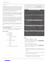 2
2
-
 3
3
-
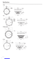 4
4
-
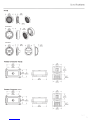 5
5
-
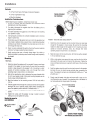 6
6
-
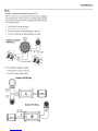 7
7
-
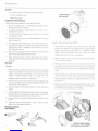 8
8
-
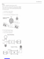 9
9
-
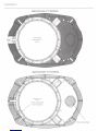 10
10
-
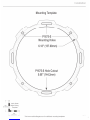 11
11
-
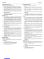 12
12
-
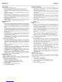 13
13
-
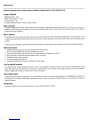 14
14
-
 15
15


punch P16-S Installation & Operation Manual
- Typ
- Installation & Operation Manual
- Dieses Handbuch eignet sich auch für
in anderen Sprachen
- English: punch P16-S
- français: punch P16-S
- italiano: punch P16-S
Andere Dokumente
-
Rockford Fosgate Punch P1675-S Installation & Operation Manual
-
-
Rockford Fosgate Punch P1692 Installation & Operation Manual
-
Rockford P1683 Spezifikation
-
Rockford Fosgate T165-S Installation & Operation Manual
-
Rockford Fosgate T1650-S Installation & Operation Manual
-
Rockford Fosgate Punch P1 serie Installation & Operation Manual
-
Audio Design Punch Serie Bedienungsanleitung
-
Rockford Fosgate power T2T-S Installation & Operation Manual
-
Frico TWT10521 Benutzerhandbuch