IMG Stage Line 20.1670 Benutzerhandbuch
- Kategorie
- Audiomischer
- Typ
- Benutzerhandbuch
Dieses Handbuch ist auch geeignet für

BPM
PROG.
MIX
PFL
MASTER
PFL
POWER
MID
–15 +15
LOW
–15 +15
MIC 1
HIGH
–15 +15
GAIN
0 MAX
AUTO TALK
ON AIR
MID
–15 +15
LOW
–15 +15
MIC 2
HIGH
–15 +15
GAIN
0 MAX
AUTO TALK
ON AIR
PHONO
LINE CD
LINE
GAIN
MIN MAX
10
9
8
7
6
5
4
3
2
1
0
GAIN
MIN MAX
10
9
8
7
6
5
4
3
2
1
0
MID
–30 +15
HIGH
–30 +15
LOW
–30 +15
2
13
4X
BPM
2
13
4X
PHONO
LINE CD
LINE
GAIN
MIN MAX
10
9
8
7
6
5
4
3
2
1
0
GAIN
MIN MAX
10
9
8
7
6
5
4
3
2
1
0
MID
–30 +15
HIGH
–30 +15
LOW
–30 +15
LEVEL
010
LEVEL
010
+9
+6
+3
0dB
–1
–3
–5
–7
–10
–20
LEVEL
010
1
CH 2
CH 3
CH 4
CH
BOOTH
MASTER PHONES
4-CHANNEL
PRO SOUND MIXER
MPX-222BPM
C.F. ASSIGN A C.F. ASSIGN B
CROSSFADER
BEAT OFFSET
PFL
EQ
PFL PFL PFL
EQ
LEFT RIGHT
CUT
CUT
CUT
CUT
CUT
CUT
MASTER LEVEL
LAMP
12V /5 W
EQ EQ
STEREO-DJ-MISCHPULT
STEREO DJ MIXER
TABLE DE MIXAGE DJ STÉRÉO
MIXER DJ STEREO
MPX-222BPM Best.-Nr. 20.2200
BEDIENUNGSANLEITUNG • INSTRUCTION MANUAL • MODE D’EMPLOI
ISTRUZIONI PER L’USO • MANUAL DE INSTRUCCIONES • VEILIGHEIDSVOORSCHRIFTEN
SIKKERHEDSOPLYSNINGER • SÄKERHETSFÖRESKRIFTER • TURVALLISUUDESTA

2
Ennen virran kytkemistä ...
Toivomme, että uusi “img Stage Line”-laitteesi
tuo sinulle paljon iloa ja hyötyä. Ole hyvä ja
lue käyttöohjeet ennen laitteen käyttöönottoa.
Luettuasi käyttöohjeet voit käyttää laitetta tur-
vallisesti ja vältyt laitteen väärinkäytöltä.
Käyttöohjeet löydät sivulta 30.
FIN
Bevor Sie einschalten ...
Wir wünschen Ihnen viel Spaß mit Ihrem
neuen Gerät von „img Stage Line“. Dabei soll
Ihnen diese Bedienungsanleitung helfen, alle
Funktionsmöglichkeiten kennen zu lernen. Die
Beachtung der Anleitung vermeidet außerdem
Fehlbedienungen und schützt Sie und Ihr
Gerät vor eventuellen Schäden durch unsach-
gemäßen Gebrauch.
Den deutschen Text finden Sie auf den Seiten
4–8.
D
A
CH
Avant toute mise en service ...
Nous vous remercions d’avoir choisi un ap-
pareil “img Stage Line” et vous souhaitons
beaucoup de plaisir à l’utiliser. Cette notice a
pour objectif de vous aider à mieux connaître
les multiples facettes de l’appareil. En outre,
en respectant les conseils donnés, vous évi-
terez toute mauvaise manipulation de sorte
que vous-même et votre appareil soient pro-
tégés de tout dommage.
La version française se trouve pages 14–18.
Voordat u inschakelt ...
Wij wensen u veel plezier met uw nieuw toe-
stel van “img Stage Line”. Lees de veiligheids-
voorschriften, alvorens het toestel in gebruik
te nemen. Door de veiligheidsvoorschriften op
te volgen zal een slechte werking vermeden
worden, en zal een eventueel letsel aan uzelf
en schade aan uw toestel tengevolge van
onzorgvuldig gebruik worden voorkomen.
U vindt de veiligheidsvoorschriften op pagi-
na 29.
NL
B
Inden De tænder for apparatet ...
Vi ønsker Dem god fornøjelse med Deres nye
“img Stage Line” apparat. Læs oplysningerne
for en sikker brug af apparatet før ibrug-
tagning. Følg sikkerhedsoplysningerne for at
undgå forkert betjening og for at beskytte
Dem og Deres apparat mod skade på grund
af forkert brug.
Sikkerhedsoplysningerne finder De på side 29.
DK
Before you switch on ...
We wish you much pleasure with your new
“img Stage Line” unit. With these operating
instructions you will be able to get to know all
functions of the unit. By following these in-
structions false operations will be avoided,
and possible damage to yourself and your
unit due to improper use will be prevented.
You will find the English text on pages 9–13.
Antes de cualquier instalación ...
Tenemos de agradecerle el haber adquirido
un aparato “img Stage Line” y le deseamos
un agradable uso. Este manual quiere ayu-
darle a conocer las multiples facetas de este
aparato. La observación de las instrucciones
evita operaciones erróneas y protege Vd. y
vuestro aparato contra todo daño posible por
cualquier uso inadecuado.
La versión española se encuentra en las pá-
ginas 24–28.
E
GB
I
S
Prima di accendere ...
Vi auguriamo buon divertimento con il Vostro
nuovo apparecchio “img Stage Line”. Le istru-
zioni per l’uso Vi possono aiutare a conoscere
tutte le possibili funzioni. E rispettando quanto
spiegato nelle istruzioni, evitate di commet-
tere degli errori, e così proteggete Voi stessi,
ma anche l’apparecchio, da eventuali rischi
per uso improprio.
Il testo italiano lo potete trovare alle pagine
19–23.
Förskrift
Vi önskar dig mycket nöje med din nya enhet
från “img Stage Line”. Läs gärna säkerhetsin-
struktionerna innan du använder enheten.
Genom att följa säkerhetsinstruktionerna kan
många problem undvikas, vilket annars kan
skada enheten.
Du finner säkerhetsinstruktionerna på sidan 30.
F
B
CH
wwwwww..iimmggssttaaggeelliinnee..ccoomm


D
A
CH
4
Bitte klappen Sie die Seite 3 heraus. Sie sehen
dann immer die beschriebenen Bedienelemente
und Anschlüsse.
Inhalt
1 Übersicht der Bedienelemente und
Anschlüsse . . . . . . . . . . . . . . . . . . . . . . . . . . 4
1.1 Frontseite . . . . . . . . . . . . . . . . . . . . . . . . . . . . 4
1.2 Rückseite . . . . . . . . . . . . . . . . . . . . . . . . . . . . 5
2 Hinweise für den sicheren Gebrauch . . . . . 5
3 Einsatzmöglichkeiten . . . . . . . . . . . . . . . . . . 5
4 Gerät anschließen . . . . . . . . . . . . . . . . . . . . 5
5 Bedienung . . . . . . . . . . . . . . . . . . . . . . . . . . . 6
5.1 Grundeinstellungen . . . . . . . . . . . . . . . . . . . . 6
5.1.1 Grundeinstellung der Kanäle CH1–CH4 . . 6
5.1.2 Grundeinstellung der Mikrofonkanäle . . . . . 6
5.2 Überblendfunktion . . . . . . . . . . . . . . . . . . . . . 7
5.3 Beatcounter . . . . . . . . . . . . . . . . . . . . . . . . . . 7
5.3.1 BPM-Displays . . . . . . . . . . . . . . . . . . . . . . . 7
5.3.2 Beat Offset-Anzeige . . . . . . . . . . . . . . . . . . . 7
5.4 Mischen der Tonquellen . . . . . . . . . . . . . . . . . 7
5.5 Talkover-Funktion . . . . . . . . . . . . . . . . . . . . . . 7
5.6 Vorhören der Kanäle über einen Kopfhörer . . 8
5.7 Abhören des Musikprogramms über eine
Monitoranlage . . . . . . . . . . . . . . . . . . . . . . . . . 8
6 Technische Daten . . . . . . . . . . . . . . . . . . . . . 8
1 Übersicht der Bedienelemente und
Anschlüsse
1.1 Frontseite
13fache Klangregelung (max. +15dB/
-
30dB) je-
weils für die Kanalgruppe CH1/CH2 und die Ka-
nalgruppe CH3/CH4:
HIGH = Höhen, MID = Mitten, LOW = Tiefen
2Stereo-VU-Meter
3Umschalttaste für das VU-Meter (2)
Taste nicht gedrückt „MASTER“:
VU-Meter zeigt den Masterpegel an
Taste gedrückt „PFL“:
VU-Meter zeigt entweder den Pre Fader-Pegel
des Eingangskanals, dessen Taste PFL (12)
gedrückt ist, an [Regler MIX (23) auf „PFL“] oder
das laufende Musikprogramm vor dem Master-
regler (21) (Regler MIX auf „PROG.“)
4BNC-Buchse LAMP zum Anschluss einer Pult-
leuchte (12V/5W max.)
5Ein-/Ausschalter POWER mit Betriebsanzeige
6Gain-Regler zum Einstellen der Eingangsverstär-
kung für die Kanäle CH1–CH4
7Eingänge (XLR, sym.) zum Anschluss von Mono-
Mikrofonen an die beiden Mikrofonkanäle; parallel
geschaltet mit den Klinkenbuchsen (32) auf der
Geräterückseite
8Pegelregler für die Mikrofonkanäle
93fache Klangregelung (max. ±15dB) für die Mikro-
fonkanäle:
HIGH = Höhen, MID = Mitten, LOW = Tiefen
10 Tasten AUTOTALK für die Talkover-Funktion:
Ist die Taste eines Mikrofonkanals gedrückt, wer-
den bei Mikrofondurchsagen über diesen Kanal die
Pegel der Eingangskanäle CH1–CH4 automa-
tisch um 15dB abgesenkt.
11 Tasten ON AIR zum Ein-/Ausschalten der Mikro-
fonkanäle
12 Tasten PFL zum Vorhören der Eingangskanäle
CH1–CH4 vor den Kanalfadern (15) über einen
an der Buchse (24) angeschlossenen Kopfhörer
13 linker Zuordnungsschalter C.F. ASSIGN A; bestimmt,
welcher der Kanäle CH1–CH4 eingeblendet wird,
wenn der Crossfader (16) links steht
Für den ausgewählten Kanal werden die Takt-
schläge pro Minute (BPM) gemessen und auf dem
linken BPM-Display (14) angezeigt.
14 BPM-Display für den Kanal, der mit dem linken
Schalter C.F. ASSIGN A (13) ausgewählt wurde:
zeigt die Taktschläge pro Minute (BPM = beats per
minute) des gerade laufenden Musikstückes an
15 Pegelregler (Fader) für die Kanäle CH1–CH4
16 Crossfader zum Überblenden zwischen zwei der
Kanäle CH1–CH4; die jeweiligen Kanäle werden
mit den Schaltern C.F. ASSIGN (13 + 19) angewählt
17 LED-Anzeige BEAT OFFSET; dient als optische
Kontrolle bei der Synchronisation der Taktschläge
der beiden Musiktitel, zwischen denen übergeblen-
det werden soll:
Je weiter innen sich die jeweils leuchtende LED in
der LED-Kette befindet, desto mehr nähern sich
die Taktschläge der beiden Musiktitel an: leuchtet
die blaue LED in der Mitte, laufen die Titel syn-
chron d.h. ihre Taktschläge liegen übereinander.
18 BPM-Display für den Kanal, der mit dem rechten
Schalter C.F. ASSIGN B (19) ausgewählt wurde:
zeigt die Taktschläge pro Minute (BPM = beats per
minute) des gerade laufenden Musikstückes an
19 rechter Zuordnungsschalter C.F. ASSIGN B; be-
stimmt, welcher der Kanäle CH1–CH4 eingeblen-
det wird, wenn der Crossfader (16) rechts steht
Für den ausgewählten Kanal werden die Takt-
schläge pro Minute (BPM) gemessen und auf dem
rechten BPM-Display (18) angezeigt.
20 Umschalttasten für die Eingänge der Kanäle
CH1–CH4
Taste nicht gedrückt:
Eingang PHONO (Kanal CH1 und CH3) bzw.
Eingang CD (Kanal CH2 und CH4) ist angewählt
Taste gedrückt:
Eingang LINE des Kanals ist angewählt
21 Masterregler

D
A
CH
5
22 Pegelregler für den Monitorausgang BOOTH (28)
23 Regler MIX für den Kopfhörerausgang (24) und
das VU-Meter (2)
Position „PFL“ (Regler ganz links):
der Pre Fader-Pegel des Eingangskanals, des-
sen Taste PFL (12) gedrückt ist, wird über den
Kopfhörer abgehört und vom VU-Meter angezeigt
Position „PROG.“ (Regler ganz rechts):
das laufende Musikprogramm wird vor dem
Masterregler (21) abgehört und vom VU-Meter
angezeigt
Hinweis:
Das VU-Meter muss auf den Kopfhörerausgang
geschaltet sein [Umschalttaste (3) gedrückt].
24 6,3-mm-Klinkenbuchse zum Anschluss eines Ste-
reo-Kopfhörers (Impedanz ≥8Ω)
25 Pegelregler für den Kopfhörerausgang (24)
1.2 Rückseite
26 Netzkabel zum Anschluss des Gerätes an die
Stromversorgung (230V~/50Hz)
27 Stereo-Ausgang REC (Cinch-Buchsen) für den An-
schluss eines Tonaufnahmegerätes; der Aufnah-
mepegel ist unabhängig von der Stellung des
Masterreglers (21)
28 Stereo-Monitorausgang BOOTH (Cinch-Buchsen)
zum Anschluss einer Monitoranlage
29 Stereo-Ausgang MASTER (Cinch-Buchsen) für den
Anschluss des Verstärkers
30 Stereo-Eingänge LINE und CD (Cinch-Buchsen)
für die Kanäle CH1–CH4 zum Anschluss von
Geräten mit Line-Pegel-Ausgängen (z.B. MiniDisk-
Recorder, CD-Spieler, Kassettenrecorder)
31 Stereo-Eingänge PHONO (Cinch-Buchsen) für die
Kanäle CH1 und CH3 zum Anschluss von Platten-
spielern mit Magnetsystem
32 Eingänge (6,3-mm-Klinkenbuchsen, sym.) zum An-
schluss von Mono-Mikrofonen an die beiden Mikro-
fonkanäle; parallel geschaltet mit den XLR-Buch-
sen (7) auf der Frontplatte
33 Anschluss GND für einen gemeinsamen Masse-
punkt, z.B. für die angeschlossenen Plattenspieler
2 Hinweise für den sicheren Gebrauch
Dieses Gerät entspricht der Richtlinie für elektroma-
gnetische Verträglichkeit 89/336/ EWG und der Nie-
derspannungsrichtlinie 73/23/EWG.
Beachten Sie auch unbedingt die folgenden Punkte:
●Verwenden Sie das Gerät nur im Innenbereich.
Schützen Sie es vor Tropf- und Spritzwasser, hoher
Luftfeuchtigkeit und Hitze (zulässiger Einsatztempe-
raturbereich 0–40°C).
●Stellen Sie keine mit Flüssigkeit gefüllten Gefäße,
z.B. Trinkgläser, auf das Gerät.
●Nehmen Sie das Gerät nicht in Betrieb bzw. ziehen
Sie sofort den Netzstecker, wenn:
1. sichtbare Schäden am Gerät oder an der Netzan-
schlussleitung vorhanden sind,
2. nach einem Sturz oder Ähnlichem der Verdacht
auf einen Defekt besteht,
3. Funktionsstörungen auftreten.
Lassen Sie das Gerät in jedem Fall in einer Fach-
werkstatt reparieren.
●Eine beschädigte Netzanschlussleitung darf nur
durch den Hersteller oder durch eine autorisierte
Fachwerkstatt ersetzt werden.
●Ziehen Sie den Netzstecker nie an der Zuleitung aus
der Steckdose, fassen Sie immer am Stecker an.
●Verwenden Sie für die Reinigung nur ein trockenes,
weiches Tuch, niemals Wasser oder Chemikalien.
●Wird das Gerät zweckentfremdet, falsch ange-
schlossen, nicht richtig bedient oder nicht fach-
gerecht repariert, kann keine Haftung für daraus
resultierende Sach- oder Personenschäden und
keine Garantie für das Gerät übernommen werden.
3 Einsatzmöglichkeiten
Das Mischpult MPX-222BPM mit vier Stereo-Kanälen,
zwei Mono-Mikrofonkanälen und integrierter Beat-
counter-Funktion ist für beliebige DJ-Anwendungen im
privaten oder professionellen Bereich geeignet.
Das Gerät kann sowohl frei aufgestellt als auch in
ein Bedienpult eingebaut werden. Es eignet sich eben-
so für die Montage in ein Rack (482mm/19"). Für die
Rackmontage wird eine Höhe von 4HE (1 Höhen-
einheit = 44,45 mm) benötigt.
4 Gerät anschließen
Vor dem Anschließen von Geräten bzw. vor dem Ändern
bestehender Anschlüsse das Mischpult ausschalten.
1) Die Stereo-Tonquellen an die entsprechenden
Cinch-Eingangsbuchsen der Kanäle CH1–CH4
anschließen (weiße Buchse L = linker Kanal; rote
Buchse R = rechter Kanal):
-
Geräte mit Line-Pegel-Ausgang (z.B. MiniDisk-
Recorder, CD-Spieler, Kassettenrecorder) an die
Buchsen CD und LINE (30);
-
Plattenspieler mit Magnetsystem an die Buchsen
PHONO (31).
Die Klemmschraube GND (33) kann als ge-
meinsamer Massepunkt genutzt werden: Den
Masseanschluss des Plattenspielers mit der
Klemmschraube verbinden.
Soll das Gerät endgültig aus dem Betrieb
genommen werden, übergeben Sie es zur
umweltgerechten Entsorgung einem örtli-
chen Recyclingbetrieb.
Achtung! Das Gerät wird mit lebensgefährlicher
Netzspannung (230V~) versorgt. Nehmen
Sie deshalb nie selbst Eingriffe am Gerät
vor. Durch unsachgemäßes Vorgehen be-
steht die Gefahr eines elektrischen Schla-
ges. Außerdem erlischt beim Öffnen des
Gerätes jeglicher Garantieanspruch.

D
A
CH
6
2) Mono-Mikrofone an die XLR-Buchsen (7) auf der
Frontplatte oder an die Klinkenbuchsen (32) auf der
Geräterückseite anschließen.
3) Den Eingang des Verstärkers an den Masteraus-
gang MASTER (29) anschließen.
4) Ist eine Monitoranlage vorhanden, den Verstärker
der Monitoranlage an den Ausgang BOOTH (28)
anschließen.
5) Sollen Tonaufnahmen gemacht werden, das Auf-
nahmegerät an den Record-Ausgang REC (27)
anschließen. Der Aufnahmepegel ist unabhängig
von der Stellung des Masterreglers (21).
6) Für eine optimale Pultbeleuchtung kann an die
BNC-Buchse LAMP (4) eine Schwanenhalsleuchte
(12V/5W max.) angeschlossen werden, z.B. die
Leuchte GNL-205 aus dem Programm von „img
Stage Line“. Die Leuchte wird mit dem Mischpult
ein- und ausgeschaltet.
7) Über einen Stereo-Kopfhörer kann sowohl der Pre
Fader-Pegel der Eingangskanäle CH1–CH4 so-
wie das laufende Musikprogramm vor dem Master-
regler (21) abgehört werden (siehe Kap. 5.6). Den
Kopfhörer (Impedanz ≥8Ω) an die Buchse (24)
anschließen.
8) Zuletzt den Stecker des Netzkabels (26) in eine
Steckdose (230V~/50Hz) stecken.
5 Bedienung
Vor dem Einschalten sollten die Ausgangsregler MA-
STER (21) und BOOTH (22) auf Minimum gestellt wer-
den, um starke Einschaltgeräusche zu vermeiden.
Dann das Mischpult mit dem Schalter POWER (5) ein-
schalten. Zur Anzeige der Betriebsbereitschaft leuch-
tet die LED über dem Schalter. Anschließend die ange-
schlossenen Geräte anschalten.
5.1 Grundeinstellungen
5.1.1 Grundeinstellung der Kanäle CH1–CH4
Für eine optimale Pegeleinstellung der an den Ein-
gangskanälen CH1–CH4 angeschlossenen Tonquel-
len alle Gain-Regler (6) und Klangregler (1) zunächst
in die Mittelposition drehen und die Schalter C.F.
ASSIGN (13 und 19) auf „x“ stellen (Überblendfunktion
ausgeschaltet).
1) Mit den Umschalttasten (20) die angeschlossenen
Signalquellen anwählen.
Taste nicht gedrückt:
Der Eingang PHONO (bei Kanal CH1 und CH3)
bzw. CD (bei Kanal CH2 und CH4) ist ange-
wählt.
Taste gedrückt – LED über der Taste leuchtet:
Der Eingang LINE des Kanals ist angewählt.
2) Mit dem Masterregler (21) wird der Gesamtpegel
aller angeschlossenen Tonquellen eingestellt. Den
Masterregler auf ca. 2/3des Maximums stellen, z.B.
auf Position 7.
3) Die Umschalttaste (3) darf nicht gedrückt sein: Bei
dieser Tastenstellung zeigt das VU-Meter (2) den
Stereo-Ausgangspegel an, der am Masterausgang
MASTER (29) zur Verfügung steht.
4) Zum Aussteuern eines Kanals die Fader (15) der
übrigen Kanäle auf Minimum stellen und die Ton-
signale (Testsignale oder Musikstücke) auf den je-
weiligen Eingangskanal geben.
5) Anhand des VU-Meters mit dem Fader den Pegel
des Kanals ausregeln. Optimale Aussteuerung liegt
vor, wenn bei den lautesten Passagen die 0-dB-
LEDs des VU-Meters aufleuchten. Übersteuerun-
gen werden durch Aufleuchten der roten LEDs an-
gezeigt.
Der Fader sollte nach der Pegeleinstellung auf
ca. 2/3des Maximums stehen, damit zum Ein- und
Ausblenden genügend Reglerweg vorhanden ist.
6) Bei sehr wenig oder sehr weit aufgezogenem Fader
muss der Pegel durch Regulierung der Eingangsver-
stärkung angepasst werden: Den GAIN-Regler (6)
des Kanals entsprechend zurück- bzw. aufdrehen
Die Eingangsverstärkung lässt sich durch Anzei-
ge des Pre Fader-Pegels optimal einstellen. Dazu
das VU-Meter durch Drücken der Taste (3) in den
Anzeigemodus „PFL“ umschalten, den Regler MIX
(23) ganz nach links auf Position „PFL“ schieben
und die Taste PFL (12) des Kanals drücken: Das
VU-Meter zeigt dann den Signalpegel des Kanals
vor dem Kanalfader an.
7) Das VU-Meter durch Lösen der Taste (3) wieder in
den Anzeigemodus „MASTER“ schalten und mit
den Klangreglern (1) des Kanals – je eine 3fache
Klangreglung für die Kanalgruppe CH1/CH2 und
die Kanalgruppe CH3/CH4 – das gewünschte
Klangbild einstellen: Mit den drei Reglern lassen
sich die Höhen (Regler HIGH), Mitten (Regler MID)
und Tiefen (Regler LOW) anheben (max. 15dB)
bzw. stark absenken (max. 30dB). Stehen die Reg-
ler in Mittelstellung, findet keine Frequenzgangbe-
einflussung statt.
Hinweis: Klangeinstellungen wirken sich auf die
Pegel aus. Deshalb nach einer Klangregulierung
den Kanalpegel anhand der Pegelanzeige kontrol-
lieren und ggf. korrigieren.
8) Die Pegel- und Klangeinstellung für die übrigen
belegten Eingangskanäle in der oben beschriebe-
nen Weise durchführen.
5.1.2 Grundeinstellung der Mikrofonkanäle
Zum Einschalten eines Mikrofonkanals die Taste ON
AIR (11) des Kanals drücken. Zur Anzeige leuchtet die
LED neben der Taste. Die Fader (15) der Eingangs-
kanäle CH1–CH4 auf Minimum stellen und anhand
des VU-Meters (2) mit dem Regler GAIN (8) des
Kanals den optimalen Pegel einstellen. Mit den Klang-
reglern (9) – HIGH für die Höhen, MID für die Mitten,
Vorsicht! Stellen Sie die Lautstärke der Audioanlage
und die Kopfhörerlautstärke nie sehr hoch ein. Hohe
Lautstärken können auf Dauer das Gehör schädigen!
Das menschliche Ohr gewöhnt sich an große Laut-
stärken und empfindet sie nach einiger Zeit als nicht
mehr so hoch. Darum eine hohe Lautstärke nach der
Gewöhnung nicht weiter erhöhen.

D
A
CH
7
LOW für die Tiefen – das Klangbild für das Mikrofon
korrigieren (max. ±15dB).
Die Pegel- und Klangeinstellungen für den zweiten
Mikrofonkanal in der gleichen Weise durchführen.
5.2 Überblendfunktion
1) Mit den zwei Zuordnungsschaltern C.F. ASSIGN
werden von den Eingangskanälen CH1–CH4 die
zwei Kanäle ausgewählt, zwischen denen überge-
blendet werden soll:
Mit dem linken Schalter C.F. ASSIGN A (13) den
Kanal wählen, der eingeblendet werden soll, wenn
der Crossfader (16) nach links geschoben wird.
Mit dem rechten Schalter C.F. ASSIGN B (19) den
Kanal wählen, der eingeblendet werden soll, wenn
der Crossfader nach rechts geschoben wird.
2) Die Fader (15) der nicht benutzten Kanäle auf Mi-
nimum stellen und die beiden ausgewählten Kanäle
mit ihren Fadern optimal aussteuern (siehe Kapitel
5.1.1).
3) Mit dem Crossfader kann jetzt zwischen den beiden
gewählten Kanälen übergeblendet werden.
Sollen beide Kanäle gleichzeitig auf die Ausgän-
ge gegeben werden, den Crossfader in die Mittel-
position stellen.
4) Mit dem Masterregler (21) den gewünschten Ge-
samtpegel einstellen, der am Masterausgang (29)
zur Verfügung steht. Bei Übersteuerungen [rote
LEDs des VU-Meters (2) leuchten auf] den Master-
pegel reduzieren.
5.3 Beatcounter
Die zwei Beatcounter des Mischpults messen für die
beiden Kanäle, die mit den Schaltern C.F. ASSIGN für
die Überblendfunktion ausgewählt wurden, die Takt-
schläge pro Minute (BPM = beats per minute). Die
gemessenen BPM werden über zwei Displays ange-
zeigt.
Hinweis: Die Beatcounter werten ausschließlich Bass-
Beats aus, die viermal hintereinander im etwa gleichen
Abstand auftreten (4/4-Takt). Musikstücke, die keine
klare Bass-Drum-Linie im 4/4-Rhythmus aufweisen,
werden von den Beatcountern nicht erkannt und mit fal-
schen Werten angezeigt.
5.3.1 BPM-Displays
Die meisten CD-Spieler für den Disco-Bereich verfü-
gen über Bedienelemente zur Veränderung der Takt-
geschwindigkeit (Pitch-Regler). Soll beim Überblen-
den zwischen den angeschlossenen Tonquellen (z.B.
zwei CD-Spieler) die Taktgeschwindigkeit des einen
Musikstückes über den Pitch-Regler an die Taktge-
schwindigkeit des anderen anpasst werden, dienen
die beiden BPM-Displays des Mischpultes als opti-
sches Hilfsmittel.
Das linke BPM-Display (14) zeigt die Beats für den
Kanal an, der mit dem linken Schalter C.F. ASSIGN A
(13) ausgewählt wurde und das rechte BPM-Display
(18) die Beats für den Kanal, der mit dem rechten
Schalter C.F. ASSIGN B (19) ausgewählt wurde. Läuft
auf dem gewählten Kanal kein Musikstück bzw. steht
der jeweilige ASSIGN-Schalter auf „x“, erscheint die
Anzeige [- - -] im Display.
Der Anzeigebereich liegt zwischen ca. 90BPM und
170BPM. Sind die BPM eines Titels niedriger, er-
scheint die Anzeige [- - -] oder ein falscher Wert im Dis-
play. Höhere BPM-Werte werden geteilt angezeigt
(z.B. Anzeige 90BPM bei einem tatsächlichen Wert
von 180BPM).
5.3.2 Beat Offset-Anzeige
Um beim Überblenden einen fließenden Übergang zwi-
schen den Titeln zu erreichen, müssen die Taktschläge
der beiden Titel synchronisiert werden, d.h. sie müssen
exakt aufeinander liegen. Über entsprechende Bedien-
elemente am CD-Spieler kann die Taktgeschwindigkeit
des eines Titels so angepasst werden, dass er syn-
chron zum zweiten Titel läuft.
Bei der Synchronisation der Taktschläge der beiden
Musiktitel, zwischen denen übergeblendet werden soll,
dient die LED-Anzeige BEAT OFFSET (17) als opti-
sche Kontrolle. Je weiter außen die jeweils leuchtende
LED in der LED-Kette liegt, desto weniger synchron
laufen die beiden Musiktitel:
Leuchtet die blaue LED in der Mitte, laufen die Titel
synchron, d.h. ihre Taktschläge liegen übereinander.
Leuchtet eine der beiden daneben liegenden LEDs,
laufen die Titel fast synchron.
Leuchtet eine der vier äußeren LEDs, laufen die
Titel nicht synchron.
Hinweis: Liegen die BPM der beiden Titel weit ausein-
ander, spricht die Beat Offset-Anzeige nicht an.
5.4 Mischen der Tonquellen
1) Zum Mischen der angeschlossenen Tonquellen die
Überblendfunktion ausschalten. Dazu die Schalter
C.F. ASSIGN (13 und 19) in die Position „x“ stellen.
2) Den Masterregler (21) so weit aufdrehen, dass das
Mischungsverhältnis der Tonquellen optimal einge-
stellt werden kann.
3) Mit den Pegelreglern der Eingangskanäle das ge-
wünschte Lautstärkeverhältnis der Tonquellen un-
tereinander einstellen. Wird ein Kanal nicht benutzt,
sollte sein Pegelregler auf Minimum gestellt werden.
4) Anhand des VU-Meters (2) mit dem Masterregler
den gewünschten Gesamtpegel einstellen, der am
Masterausgang (29) zur Verfügung steht.
Optimale Aussteuerung liegt vor, wenn bei den
lautesten Passagen der 0-dB-Bereich des VU-Me-
ters aufleuchtet. Bei Übersteuerungen (rote LEDs
leuchten) den Ausgangspegel mit dem Masterregler
und/oder den Pegelreglern der Eingangskanäle
reduzieren.
5.5 Talkover-Funktion
Die Talkover-Funktion dient zur besseren Verständlich-
keit von Mikrofondurchsagen bei laufendem Musik-
programm. Zum Aktivieren der Funktion für einen Mi-
krofonkanal die Taste AUTOTALK (10) des Kanals
drücken: Ist die Taste gedrückt (LED neben der Taste
leuchtet), werden bei Mikrofondurchsagen über diesen
Kanal die Pegel der Kanäle CH1–CH4 automatisch

D
A
CH
8
um 15dB abgesenkt. Zum Abschalten der Funktion die
Taste wieder lösen.
5.6 Vorhören der Kanäle über einen Kopfhörer
Über die Vorhörfunktion (PFL = Pre Fader Listening)
ist es möglich, jeden der Eingangskanäle CH1–CH4
über einen an der Buchse (24) angeschlossenen
Kopfhörer abzuhören, auch wenn der dazugehörige
Kanalfader (15) auf Minimum steht. Dadurch kann z.B.
auf einer CD der gewünschte Titel ausgewählt oder
der richtige Zeitpunkt zum Einblenden einer Tonquelle
abgepasst werden.
Wahlweise ist es auch möglich, das laufende Mu-
sikprogramm vor dem Masterregler (21) abzuhören.
1) Zum Abhören eines Eingangskanals vor dem Ka-
nalfader die Taste PFL (12) des Kanals drücken
(LED über der Taste leuchtet), und den Regler MIX
(23) ganz nach links schieben (Position „PFL“).
Zum Abhören des laufenden Musikprogramms
vor dem Masterregler den Regler MIX ganz nach
rechts schieben (Position „PROG.“).
2) Zum Umschalten des VU-Meters (2) auf den Kopf-
hörerausgang die Taste (3) drücken. Das VU-Meter
zeigt dann das Signal, das mit dem Regler MIX (23)
gewählt wurde.
3) Mit dem Pegelregler (25) die gewünschte Kopf-
hörerlautstärke einstellen.
5.7 Abhören des Musikprogramms über eine
Monitoranlage
Es besteht die Möglichkeit, das laufende Musikpro-
gramm vor dem Masterregler (21) über eine an den
Buchsen BOOTH (28) angeschlossene Monitoranlage
abzuhören. Den Pegel für die Monitoranlage mit dem
Regler BOOTH (22) einstellen.
6 Technische Daten
Eingänge
Mic, mono: . . . . . . . . . . . 1,5mV
Phono, stereo: . . . . . . . . 2,7mV
Line und CD, stereo: . . . 130mV
Ausgänge
Master, stereo: . . . . . . . . 1V
Booth (Monitor), stereo: . 1V
Record, stereo:. . . . . . . . 0,5V
Kopfhörer, stereo:. . . . . . ≥8Ω
Allgemeine Daten
Frequenzbereich: . . . . . . 20–20000Hz
Klirrfaktor:. . . . . . . . . . . . 0,1%
Störabstand.. . . . . . . . . . > 53dB
Klangregelung CH1–CH4
Tiefen: . . . . . . . . . . . . +15dB,
-
30dB/50Hz
Mitten: . . . . . . . . . . . . +15dB,
-
30dB/1kHz
Höhen: . . . . . . . . . . . . +15dB,
-
30dB/10kHz
Klangregelung Mic
Tiefen: . . . . . . . . . . . . ±15dB/50Hz
Mitten: . . . . . . . . . . . . ±15dB/1kHz
Höhen: . . . . . . . . . . . . ±15dB/10kHz
Talkover (automatisch): .
-
15dB
Anschluss für Pultleuchte: 12V/5W max., BNC
Einsatztemperatur:. . . . . 0–40°C
Stromversorgung:. . . . . . 230V~/50Hz
Leistungsaufnahme:. . . . 10VA
Abmessungen : . . . . . . . 482 x 178 x 105mm, 4 HE
Gewicht: . . . . . . . . . . . . . 3,8kg
Änderungen vorbehalten.
Diese Bedienungsanleitung ist urheberrechtlich für MONACOR®INTERNATIONAL GmbH & Co. KG geschützt.
Eine Reproduktion für eigene kommerzielle Zwecke – auch auszugsweise – ist untersagt.

Please unfold page 3. Then you can always see the
operating elements and connections described.
Contents
1 Operating Elements and Connections . . . . 9
1.1 Front side . . . . . . . . . . . . . . . . . . . . . . . . . . . . 9
1.2 Rear side . . . . . . . . . . . . . . . . . . . . . . . . . . . 10
2 Safety Notes . . . . . . . . . . . . . . . . . . . . . . . . 10
3 Applications . . . . . . . . . . . . . . . . . . . . . . . . 10
4 Connection of the Unit . . . . . . . . . . . . . . . . 10
5 Operation . . . . . . . . . . . . . . . . . . . . . . . . . . . 11
5.1 Basic settings . . . . . . . . . . . . . . . . . . . . . . . . 11
5.1.1 Basic setting of channels CH1 to CH4 . . . 11
5.1.2 Basic setting of the microphone channels . 11
5.2 Crossfading function . . . . . . . . . . . . . . . . . . . 12
5.3 Beat counter . . . . . . . . . . . . . . . . . . . . . . . . . 12
5.3.1 BPM displays . . . . . . . . . . . . . . . . . . . . . . . 12
5.3.2 Beat Offset display . . . . . . . . . . . . . . . . . . . 12
5.4 Mixing of the audio sources . . . . . . . . . . . . . 12
5.5 Talkover function . . . . . . . . . . . . . . . . . . . . . . 12
5.6 Pre fader listening of the channels
via headphones . . . . . . . . . . . . . . . . . . . . . . 13
5.7 Monitoring of the music programme
via a monitor system . . . . . . . . . . . . . . . . . . . 13
6 Specifications . . . . . . . . . . . . . . . . . . . . . . . 13
1 Operating Elements and Connections
1.1 Front side
13-way equalizer (max. +15 dB/
-
30 dB), each for
the channel group CH1/CH2 and the channel
group CH3/CH4: HIGH = high range, MID = mid-
range, LOW = bass range
2Stereo VU meter
3Selector button for the VU meter (2)
Button not pressed “MASTER”:
the VU meter shows the master level
Button pressed “PFL”:
the VU meter shows either the pre fader level of
the input channel, of which the PFL button (12) is
pressed [control MIX (23) set to “PFL”], or the
current music programme ahead of the master
control (21) (control MIX set to “PROG.”)
4BNC jack LAMP for the connection of a console
lamp (12V/5W max.)
5On/off POWER switch with operation indication
6GAIN controls for adjusting the input amplification
for the channels CH1 to CH4
7Inputs (XLR, bal.) for the connection of mono
microphones to the two microphone channels; con-
nected in parallel to the 6.3mm jacks (32) on the
rear side of the unit
8Level controls for the microphone channels
93-way equalizer (max. ±15dB) for the microphone
channels: HIGH = high range, MID = midrange,
LOW = bass range
10 AUTO TALK buttons for the talkover function:
If the button of a microphone channel is pressed,
the levels of the input channels CH1 to CH4 are
automatically attenuated by 15dB in case of micro-
phone announcements via this channel.
11 ON AIR buttons for switching on/off the micro-
phone channels
12 PFL buttons for pre fader listening of the input
channels CH1 to CH4 (15) via headphones con-
nected to jack (24)
13 Left C.F. ASSIGN A switch; defines which of the
channels CH1 to CH4 is faded in if the crossfader
(16) is in the left position
For the selected channel the beats per minute
(BPM) are measured and shown on the left BPM
display (14).
14 BPM display for the channel selected with the left
C.F. ASSIGN A switch (13):
shows the beats per minute (BPM) of the music
piece currently playing
15 Level controls (faders) for channels CH1 to CH4
16 Crossfader for fading between two of the channels
CH1 to CH4; the respective channels are selected
with the C.F. ASSIGN switches (13 and 19)
17 LED indication BEAT OFFSET; serves as optical
control when synchronizing the beats of the two
music titles to be crossfaded
The further inside the corresponding LED lighting
up is located in the LED row, the more the beats
of the two music titles approach each other: if the
blue LED in the centre lights up, the titles are syn-
chronized, i.e. their beats are exactly the same.
18 BPM display for the channel selected with the right
C.F. ASSIGN B switch (19):
shows the beats per minute (BPM) of the music
piece currently playing
19 Right C.F. ASSIGN B switch; defines which of the
channels CH1 to CH4 is faded in if the crossfader
(16) is in the right position
For the selected channel the beats per minute
(BPM) are measured and shown on the right BPM
display (18).
20 Selector buttons for the inputs of channels CH1 to
CH4
button not pressed:
PHONO input (channels CH1 and CH3) or CD
input (channels CH2 and CH4) is selected
button pressed:
LINE input of the channel is selected
21 Master control
22 Level control for the monitor output BOOTH (28)
GB
9

GB
10
23 Control MIX for the headphone output (24) and
the VU meter (2)
“PFL” (control in the extreme left position):
the pre fader level of the input channel, of which
the PFL button (12) is pressed, is monitored via
headphones and displayed by the VU meter
“PROG.” (control in the extreme right position):
the current music programme is monitored ahead
of the master control (21) and displayed by the
VU meter
Note: The VU meter must be switched to the head-
phone output [selector button (3) pressed].
24 6.3mm jack for the connection of stereo head-
phones (impedance ≥8Ω)
25 Level control for the headphone output (24)
1.2 Rear side
26 Mains cable for the connection of the unit to the
power supply (230V~/50Hz)
27 Stereo output REC (phono jacks) for the connec-
tion of an audio recording unit; the recording level is
independent of the position of the master control
(21)
28 Stereo monitor output BOOTH (phono jacks) for
the connection of a monitor system
29 Stereo output MASTER (phono jacks) for the
connection of the amplifier
30 Stereo inputs LINE and CD (phono jacks) for the
channels CH1 to CH4 for the connection of units
with line level outputs (e.g. minidisk recorder, CD
player, cassette recorder)
31 Stereo inputs PHONO (phono jacks) for the chan-
nels CH1 and CH3 for the connection of turntables
with magnetic system
32 Inputs (6.3mm jacks, bal.) for the connection of
mono microphones to the two microphone chan-
nels; connected in parallel to the XLR jacks (7) on
the front plate
33 GND connection for a common grounding point,
e.g. for the connected turntables
2 Safety Notes
This unit corresponds to the directive for electromag-
netic compatibility 89/336/EEC and the low voltage
directive 73/23/EEC.
Also observe the following items in any case:
●The unit is suitable for indoor use only. Protect it
against dripping water and splash water, high air
humidity, and heat (admissible ambient temperature
range 0–40°C).
●Do not place any vessels filled with liquid, e.g. drink-
ing glasses, on the unit.
●Do not set the unit into operation and immediately
disconnect the mains plug from the mains socket if:
1. there is visible damage to the unit or mains cable,
2. a defect might have occurred after a drop or simi-
lar accident,
3. there are malfunctions.
The unit must in any case be repaired by authorized,
skilled personnel.
●A damaged mains cable must only be replaced by
the manufacturer or authorized, skilled personnel.
●Never pull the mains cable to disconnect the mains
plug from the mains socket, always seize the plug.
●For cleaning only use a dry, soft cloth, by no means
chemicals or water.
●If the unit is used for purposes other than originally
intended, if it is not correctly connected or operated,
or not repaired in an expert way, there is no liability
for resulting damage to persons or material and no
guarantee for the unit can be taken over.
●Important for U.K. Customers!
The wires in this mains lead are coloured in accord-
ance with the following code:
blue = neutral; brown = live
As the colours of the wires in the mains lead of this
appliance may not correspond with the coloured
markings identifying the terminals in your plug, pro-
ceed as follows:
1. The wire which is coloured blue must be con-
nected to the terminal in the plug which is marked
with the letter N or coloured black.
2. The wire which is coloured brown must be
connected to the terminal which is marked with
the letter Lor coloured red.
3 Applications
The mixer MPX-222BPM with four stereo channels,
two mono microphone channels, and integrated beat
counter function is suitable for any desired private or
professional DJ applications.
The unit can be placed as a table top unit as well as
be installed into a console. It is suitable for rack mount-
ing (482mm/19") as well. For rack mounting a height of
4 rack spaces (1 rack space = 44.45mm) is necessary.
4 Connection of the Unit
Prior to the connection of units or changing of existing
connections, switch off the mixer.
1) Connect the stereo audio sources to the corre-
sponding phono input jacks of channels CH1 to
CH4 (white jack L = left channel; red jack R = right
channel):
If the unit is to be put out of operation defi-
nitively, take it to a local recycling plant for
a disposal which is not harmful to the en-
vironment.
Attention! This unit uses dangerous mains voltage
(230V~). To prevent a shock hazard, do
not open the cabinet. Leave servicing to
authorized skilled personnel only. Any
guarantee claim expires if the unit has been
opened.

-
units with line level output (e.g. mindisk recorder,
CD player, cassette recorder) to the jacks CD
and LINE (30);
-
turntables with magnetic system to the PHONO
jacks (31).
The clamping screw GND (33) can be used as
common grounding point: connect the grounding
connection of the turntable to the clamping
screw.
2) Connect mono microphones to the XLR jacks (7) on
the front plate or to the 6.3mm jacks (32) on the
rear side of the unit.
3) Connect the input of the amplifier to the master out-
put MASTER (29).
4) If a monitor system is present, connect the amplifier
of the monitor system to the BOOTH output (28).
5) For audio recordings, connect the recording unit to
the record output REC (27). The recording level is
independent of the position of the master control
(21).
6) For an optimum console illumination a gooseneck
lamp (12V/5W max.) can be connected to the BNC
jack LAMP (4), e.g. the lamp GNL-205 of the “img
Stage Line” range. The lamp is switched on and off
with the mixer.
7) Via stereo headphones the pre fader level of the
input channels CH1 to CH4 as well as the current
music programme ahead of the master control (21)
can be monitored (see chapter 5.6). Connect the
headphones (impedance ≥8Ω) to the jack (24).
8) Finally connect the plug of the mains cable (26) to a
mains socket (230V~/50Hz).
5 Operation
Prior to switching on, the output controls MASTER (21)
and BOOTH (22) should be set to minimum to avoid
strong inrush noise. Then switch on the mixer with the
POWER switch (5). The LED above the switch lights
up to indicate that the unit is ready for operation. Then
switch on the connected units.
5.1 Basic settings
5.1.1 Basic setting of channels CH1 to CH4
For an optimum level adjustment of the audio sources
connected to the input channels CH1 to CH4, turn all
gain controls (6) and equalizer controls (1) to mid-posi-
tion first, and set the C.F. ASSIGN switches (13 and
19) to “x” (crossfading function switched off).
1) Select the connected signal sources with the se-
lector buttons (20).
Button not pressed:
the PHONO input (for channels CH1 and CH3)
or the CD input (for channels CH2 and CH4) is
selected.
Button pressed – LED above the button lights up:
the LINE input of the channel is selected.
2) With the master control (21) the total level of all
connected audio sources is adjusted. Set the mas-
ter control to approx. 2/3of its maximum position,
e.g. to position 7.
3) The selector button (3) must not be pressed: with
this button position the VU meter (2) shows the
stereo output level which is present at the master
output MASTER (29).
4) To control a channel, set the faders (15) of the
remaining channels to minimum and feed the audio
signals (test signals or music pieces) to the respec-
tive input channel.
5) By means of the VU meter control the level of the
channel with the fader. The optimum level is ob-
tained if the 0dB LEDs of the VU meter light up with
music peaks. In case of overload the red LEDs light
up.After the level adjustment the fader should be
set to approx. 2/3of its maximum position so that
there is sufficient control range for fading in and out.
6) If the fader is slided up very much or only very little,
the level must be matched by adjusting the input
amplification: turn back or turn up the gain control
(6) of the channel correspondingly.
The input amplification can be adjusted in an
optimum way by the display of the pre fader level.
For this purpose press the button (3) to switch the
VU meter to the display mode “PFL”, slide the con-
trol MIX (23) to the left stop to position “PFL”, and
press the PFL button (12) of the channel: the VU
meter now shows the signal level of the channel
ahead of the channel fader.
7) Release button (3) to switch the VU meter to the
display mode “MASTER” again, and adjust the de-
sired sound with the equalizer controls (1) of the
channel – a 3-way equalizer each for the channel
group CH1/CH2 and the channel group CH3/CH4:
with the three controls the high range (HIGH con-
trols), the midrange (MID controls), and the bass
range (LOW controls) can be boosted (max. 15dB)
or attenuated to a large extent (max. 30dB). If the
controls are in mid-position, there is no influence on
the frequency response.
Note: Sound adjustments influence the levels.
Therefore, after a sound adjustment, check the
channel level by means of the level display and cor-
rect it, if necessary.
8) Make the level and sound adjustments for the re-
maining connected input channels as described
above.
5.1.2 Basic setting of the microphone channels
To switch on a microphone channel, press the ON AIR
button (11) of the channel. The LED next to the button
lights up as indication. Set the faders (15) of the input
Caution! Never adjust the audio system or the head-
phones to a very high volume. Permanent high vol-
umes may damage your hearing! The human ear will
get accustomed to high volumes which do not seem
to be that high after some time. Therefore, do not fur-
ther increase a high volume after getting used to it.
GB
11

GB
12
channels CH1 to CH4 to minimum, and adjust the
optimal level with the GAIN control (8) of the channel
by means of the VU meter (2). Correct the sound for
the microphone (max. ±15dB) with the equalizer con-
trols (9) – HIGH for the high range, MID for the mid-
range, LOW for the bass range.
Make the level and sound adjustments for the
second microphone channel in the same way.
5.2 Crossfading function
1) With the two C.F. ASSIGN switches select the two
channels of the input channels CH1–CH4 to be
crossfaded:
With the left C.F. ASSIGN A switch (13) select the
channel to be faded in if the crossfader (16) is slid
to the left.
With the right C.F. ASSIGN B switch (19) select the
channel to be faded in if the crossfader is slid to the
right.
2) Set the faders (15) of the channels not used to mini-
mum and control the two selected channels with
their faders in an optimum way (see chapter 5.1.1).
3) With the crossfader, it is now possible to fade be-
tween the two selected channels.
If both channels are to be fed to the outputs at the
same time, set the crossfader to the mid-position.
4) With the master control (21) adjust the desired total
level which is available at the master output (29). In
case of overload [red LEDs of the VU meter (2) light
up] reduce the master level.
5.3 Beat counter
The two beat counters of the mixer measure the beats
per minute (BPM) for the two channels selected with
the C.F. ASSIGN switches for the crossfading function.
The measured BPM are shown via two displays.
Note: the beat counters only evalute bass beats which
occur four times in succession at approx. the same
distance (4/4beat). Music pieces which do not show
any clear bass drum line in the 4/4rhythm are not reco-
gnized by the beat counters and displayed with wrong
values.
5.3.1 BPM displays
Most CD players for disco applications are provided
with operating elements to change the speed of the
beat (pitch controls). For matching the pitch of one
music piece to that of the other via the pitch control
when crossfading between the connected audio sour-
ces (e.g. two CD players), the two BPM displays of the
mixer serve as optical aid.
The left BPM display (14) shows the beats for the
channel selected with the left C.F. ASSIGN A switch
(13) and the right BPM display (18) the beats for the
channel selected with the right C.F. ASSIGN B switch
(19). If no music piece is playing on the selected chan-
nel or if the respective ASSIGN switch is set to “x”, the
display is [- - -].
The display range is between approx. 90 BPM and
170 BPM. If the BPM of a title are lower, the display is
[- - -] or a wrong value. Higher BPM values are dis-
played in a divided way (e.g. display 90 BPM in case
of an actual value of 180 BPM).
5.3.2 Beat Offset display
To obtain a smooth transition between the titles when
crossfading, the beats of both titles have to be syn-
chronized, i.e. they must be exactly the same. Via cor-
responding operating elements on the CD player the
pitch of one title can be matched so that it is syn-
chronized with the second title.
When synchronizing the beats of the two music
titles to be crossfaded, the LED indication BEAT OFF-
SET (17) serves as optical control. The further outside
the corresponding LED lighting up is located in the LED
row, the less the two music titles are synchronized:
If the blue LED in the centre lights up, the titles are
synchronized, i.e. their beats are exactly the same.
If one of the two LEDs next to it lights up, the titles
are almost synchronized.
If one of the four outer LEDs lights up, the titles are
not synchronized.
Note: If the BPM of the two titles are far away from
each other, the beat offset display does not respond.
5.4 Mixing of the audio sources
1) To mix the connected audio sources, switch off the
crossfading function. For this purpose, set the C.F.
ASSIGN switches (13 and 19) to position “x”.
2) Turn up the master control (21) so much that the
mixing relation of the audio sources can be ad-
justed in an optimum way.
3) With the level controls of the input channels adjust
the desired volume relation of the audio sources
with each other. If a channel is not used, its level
control should be set to minimum.
4) By means of the VU meter (2) adjust with the mas-
ter control the desired total level which is available
at the master output (29).
The optimum level is obtained if the 0dB range
of the VU meter lights up with music peaks. In case
of overload (red LEDs light up), reduce the output
level with the master control and/or the level con-
trols of the input channels.
5.5 Talkover function
The talkover function serves for better intelligibility
of microphone announcements during the music pro-
gramme. To activate the funcion for a microphone
channel, press the AUTO TALK button (10) of the
channel: if the button is pressed (LED next to the but-
ton lights up), the levels of the channels CH1 to CH4
are automatically attenuated by 15dB during micro-
phone announcements. To switch off the function, re-
lease the button again.

5.6 Pre fader listening (PFL) of the channels via
headphones
Via the pre fader listening function each of the input
channels CH1 to CH4 can be monitored via head-
phones connected to the jack (24), even if the
corresponding channel fader (15) is set to minimum.
Thus, e.g. the desired title on a CD can be selected or
the right moment for fading in an audio source can be
timed.
Alternatively it is also possible to monitor the music
programme currently playing ahead of the master con-
trol (21).
1) To monitor an input channel ahead of the channel
fader, press the PFL button (12) of the channel
(LED above the button lights up) and slide the con-
trol MIX (23) to the extreme left position (“PFL”).
To monitor the current music programme ahead
of the master control, slide the control MIX to the
extreme right position (“PROG.”).
2) To switch the VU meter (2) to the headphone out-
put, press the button (3). Then the VU meter shows
the signal selected with the control MIX (23).
3) With the level control (25) adjust the desired head-
phone volume.
5.7 Monitoring of the music programme via a
monitor system
The music programme currently playing can be moni-
tored ahead of the master control (21) via a monitor
system connected to the BOOTH jacks (28). Adjust the
level for the monitor system with the BOOTH control
(22).
6 Specifications
Inputs
Mic, mono: . . . . . . . . . . . 1.5mV
Phono, stereo: . . . . . . . . 2.7mV
Line and CD, stereo: . . . 130mV
Outputs
Master, stereo: . . . . . . . . 1V
Booth (monitor), stereo: . 1V
Record, stereo:. . . . . . . . 0.5V
Headphones, stereo: . . . ≥8Ω
General information
Frequency range:. . . . . . 20–20000Hz
THD:. . . . . . . . . . . . . . . . 0.1%
S/N ratio: . . . . . . . . . . . . > 53dB
Equalizer CH1 to CH4
bass:. . . . . . . . . . . . . . +15dB,
-
30dB/50Hz
mid: . . . . . . . . . . . . . . +15dB,
-
30dB/1kHz
high: . . . . . . . . . . . . . . +15dB,
-
30dB/10kHz
Equalizer Mic
bass:. . . . . . . . . . . . . . ±15dB/50Hz
mid: . . . . . . . . . . . . . . ±15dB/1kHz
high: . . . . . . . . . . . . . . ±15dB/10kHz
Talkover (automatic): . . .
-
15dB
Connection for
console lamp:. . . . . . . . . 12V/5W max., BNC
Ambient temperature:. . . 0–40°C
Power supply:. . . . . . . . . 230V~/50Hz
Comsumption: . . . . . . . . 10VA
Dimensions: . . . . . . . . . . 482 x 178 x 105mm,
4 rack spaces
Weight:. . . . . . . . . . . . . . 3.8kg
Subject to change.
GB
13
All rights reserved by MONACOR ®INTERNATIONAL GmbH & Co. KG. No part of this instruction manual may
be reproduced in any form or by any means for any commercial use.

Ouvrez le présent livret page 3 de manière à visua-
liser les éléments et branchements.
Table des matières
1 Eléments et branchements . . . . . . . . . . . . 14
1.1 Face avant . . . . . . . . . . . . . . . . . . . . . . . . . . 14
1.2 Face arrière . . . . . . . . . . . . . . . . . . . . . . . . . 15
2 Conseils d’utilisation . . . . . . . . . . . . . . . . . 15
3 Possibilités d’utilisation . . . . . . . . . . . . . . 15
4 Branchements . . . . . . . . . . . . . . . . . . . . . . . 15
5 Fonctionnement . . . . . . . . . . . . . . . . . . . . . 16
5.1 Réglages de base . . . . . . . . . . . . . . . . . . . . . 16
5.1.1 Réglage de base des canaux CH1–CH4 16
5.1.2 Réglage de base des canaux micro . . . . . . 16
5.2 Fondu-enchaîné . . . . . . . . . . . . . . . . . . . . . . 16
5.3 Compteur de beats . . . . . . . . . . . . . . . . . . . . 17
5.3.1 Affichage BPM . . . . . . . . . . . . . . . . . . . . . . 17
5.3.2 Affichage Beat Offset . . . . . . . . . . . . . . . . . 17
5.4 Mixage des sources . . . . . . . . . . . . . . . . . . . 17
5.5 Fonction Talkover . . . . . . . . . . . . . . . . . . . . . 17
5.6 Préécoute des canaux via un casque . . . . . . 17
5.7 Préécoute du programme musical
via un système Monitor . . . . . . . . . . . . . . . . . 18
6 Caractéristiques techniques . . . . . . . . . . . 18
1 Eléments et branchements
1.1 Face avant
1Egaliseur 3 voies (+15dB/
-
30dB max.) respec-
tivement pour le groupe CH1/CH2 et le groupe
CH3/CH4 :
HIGH : aigus, MID : médiums, LOW : graves
2VU-mètre stéréo
3Commutateur pour le VU-mètre (2) :
touche non enfoncée “MASTER” :
le VU-mètre indique le niveau Master
touche enfoncée “PFL” :
indique soit le niveau pré fader du canal d’entrée
dont la touche PFL (12) est enfoncée [poten-
tiomètre MIX (23) sur “PFL”] soit le programme
musical en cours avant le réglage Master (21)
[potentiomètre MIX (23) sur “PROG.”]
4Prise BNC LAMP pour brancher une lampe col de
cygne 12V/5W max.
5Interrupteur POWER Marche/Arrêt avec témoin de
fonctionnement
6Potentiomètres de réglage de gain : réglage de
l’amplification d’entrée pour les canaux CH1–CH4
7Entrées (XLR symétriques) pour brancher des
micros mono aux 2 canaux micro ; branchées en
parallèle avec les prises Jack 6,35 (32) de la face
arrière
8Potentiomètres de réglages de niveau pour les
canaux micro
9Egaliseur 3 voies (±15dB max) pour les canaux
micro : HIGH : aigus, MID : médiums, LOW : graves
10 Touches AUTO TALK pour la fonction Talkover :
Si la touche d’un canal micro est enfoncée, les ni-
veaux des canaux d’entrée CH1–CH4 sont auto-
matiquement diminués de 15dB lors d’annonces
micro.
11 Touches ON AIR : marche/arrêt des canaux micro
12 Touches PFL : préécoute des canaux d’entrée
CH1–CH4 avant les faders des canaux (15), via
un casque relié à la prise (24)
13 Commutateur d’attribution C.F. ASSIGN Agauche :
détermine quel canal CH1–CH4 est utilisé pour le
fondu-enchaîné lorsque le potentiomètre de fondu-
enchaîné (16) est à gauche
Pour le canal sélectionné, le nombre de beats par
minute (BPM) est mesuré et affiché sur l’affichage
gauche BPM (14).
14 Affichage BPM pour le canal sélectionné avec le
commutateur C.F. ASSIGN A (13) gauche :
indique le nombre de beats par minute (BPM) pour
le morceau en cours
15 Potentiomètres de réglage de niveau (faders) pour
les canaux CH1–CH4
16 Potentiomètre pour effectuer un fondu-enchaîné
entre deux des canaux CH1–CH4 ; les canaux
sont sélectionnés avec les commutateurs C.F.
ASSIGN (13 et 19)
17 LEDs BEAT OFFSET : servent de contrôle optique
lors de la synchronisation des beats des 2 titres
entre lesquels le fondu-enchaîné est effectué
Plus la LED correspondante qui brille est vers
l’intérieur de la chaîne des LEDs, plus les ryth-
mes des deux titres de musique sont proches ; si
la LED bleue au milieu brille, les titres défilent de
manière synchrone, c’est-à-dire que leurs ryth-
mes coïncident.
18 Affichage BPM pour le canal sélectionné avec le
commutateur C.F. ASSIGN B (19) droit :
indique le nombre de beats par minute (BPM) du
morceau en cours
19 Commutateur d’attribution C.F. ASSIGN B droit :
détermine quel canal CH1–CH4 est utilisé pour le
fondu-enchaîné lorsque le potentiomètre de fondu-
enchaîné (16) est à droite
Pour le canal sélectionné, le nombre de beats par
minute (BPM) est mesuré et affiché sur l’affichage
droit BPM (18).
20 Commutateurs pour les entrées des canaux
CH1–CH4
touche non enfoncée :
entrée PHONO (canal CH1 et CH3) ou entrée
CD (canal CH2 et CH4) sélectionnée
F
B
CH
14

touche enfoncée :
entrée LINE du canal sélectionnée
21 Réglage Master
22 Réglage de niveau pour la sortie Monitor BOOTH
(28)
23 Potentiomètre MIX pour la sortie casque (24) et
le VU-mètre (2)
Position “PFL” (potentiomètre à gauche) :
le niveau pré fader du canal d’entrée dont la tou-
che PFL (12) est enfoncée, est écouté dans le
casque et affiché par le VU-mètre
Position “PROG.” (potentiomètre à droite) :
le programme musical en cours est écouté avant
le réglage Master (12) et affiché par le VU-mètre
Conseil : le VU-mètre doit être commuté sur la sor-
tie casque [touche (3) enfoncée].
24 Prise Jack 6,35 pour brancher un casque stéréo
(impédance ≥8Ω)
25 Potentiomètre de réglage de niveau pour la sortie
casque (24)
1.2 Face arrière
26 Cordon secteur d’alimentation 230V~/50Hz
27 Sortie stéréo REC (prises RCA) pour brancher un
enregistreur ; le niveau d’enregistrement est indé-
pendant de la position du réglage Master (21)
28 Sortie Monitor stéréo BOOTH (prises RCA) pour
brancher un système monitor
29 Sortie MASTER (prises RCA) pour brancher l’am-
plificateur
30 Entrées stéréo LINE et CD (prises RCA) pour les
canaux CH1–CH4 pour brancher des appareils à
sorties niveau Ligne (enregistreur de mini-disques,
lecteur CD, platine-cassette etc.)
31 Entrées stéréo PHONO (prises RCA) pour les
canaux CH1 et CH3 pour brancher des platine
diques à système magnétique
32 Entrées (prises Jack 6,35 symétriques) pour bran-
cher des micros mono aux deux canaux micro ;
branchées en parallèle aux prises XLR (7) de la
face avant
33 Branchement GND pour un point de masse com-
mun, par exemple pour les platine disques reliées
2 Conseils d’utilisation
La MPX-222BPM répond à la norme européenne
89/336/CEE relative à la compatibilité électromagné-
tique et à la norme 73/23/CEE portant sur les ap-
pareils à basse tension.
Respectez scrupuleusement les points suivants :
●L’appareil n’est conçu que pour une utilisation en
intérieur. Protégez-le des éclaboussures, de tout
type de projections d’eau, de l’humidité et de la cha-
leur (température ambiante admissible 0–40°C).
●En aucun cas, vous ne devez poser d’objet conte-
nant du liquide ou un verre sur l’appareil.
●Ne faites pas fonctionner l’appareil ou débranchez im-
médiatement la prise du cordon du secteur lorsque :
1. des dommages sur l’appareil apparaissent.
2. après une chute ou un cas similaire, vous avez un
doute sur l’état de l’appareil.
3. des défaillances apparaissent.
Dans tous les cas, les dommages doivent être ré-
parés par un technicien spécialisé.
●Tout cordon secteur endommagé doit être remplacé
par le fabricant ou un technicien habilité.
●Ne débranchez jamais l’appareil en tirant sur le cor-
don secteur, tenez-le toujours par la prise.
●Pour nettoyer l’appareil, utilisez uniquement un chif-
fon sec et doux, en aucun cas, de produits chimi-
ques ou d’eau.
●Nous déclinons toute responsabilité en cas de dom-
mages corporels ou matériels résultants si l’appareil
est utilisé dans un but autre que celui pour lequel il a
été conçu, s’il n’est pas correctement branché, uti-
lisé ou n’est pas réparé par une personne habilitée,
de même, la garantie deviendrait caduque.
3 Possibilités d’utilisation
La table de mixage MPX-222BPM est équipée de qua-
tre canaux stéréo, deux canaux micro mono et d’une
fonction compteur de beats ; elle est particulièrement
bien adaptée à des utilisations DJ privées ou profes-
sionnelles.
L’appareil peut être placé directement sur une table
ou dans un pupitre. Il est également possible de le mon-
ter dans un rack au standard 482mm(19"), 4 unités de
hauteur (1 unité = 44,45mm) sont alors nécessaires.
4 Branchements
Avant d’effectuer tout branchement ou de les modifier,
éteignez la table.
1) Reliez les sources stéréo aux prises d’entrée RCA
correspondantes des canaux CH1–CH4 (prise
blanche L = canal gauche, prise rouge R = canal
droit) :
-
appareils à sortie niveau Ligne (par exemple, lec-
teur CD, enregistreur de mini-disques, platine-
cassette) aux prises CD ou LINE (30) ;
-
platine disques à système magnétique aux prises
PHONO (31). La borne GND (33) peut être utilisée
comme point de masse commun : reliez le bran-
chement masse de la platine disques à la borne.
Lorsque l’appareil est définitivement retiré
du service, vous devez le déposer dans
une usine de recyclage adaptée pour con-
tribuer à son élimination non polluante.
Attention ! La table de mixage est alimentée par une
tension dangereuse en 230V~. Ne tou-
chez jamais l'intérieur de l'appareil, car
en cas de mauvaise manipulation vous
pourriez subir une décharge électrique
mortelle. En outre, l’ouverture de l’appa-
reil rend tout droit à la garantie caduque.
F
B
CH
15

2) Reliez les micros mono aux prises XLR (7) de la
face avant ou aux prises Jack (32) de la face
arrière.
3) Reliez l’entrée de l’amplificateur à la sortie Master
MASTER (29).
4) Si un système Monitor est prévu, reliez l’amplifica-
teur du système à la sortie BOOTH (28).
5) Si des enregistrements doivent être effectués, con-
nectez l’enregistreur à la sortie REC (27) ; le niveau
d’enregistrement est indépendant de la position du
réglage Master (21).
6) Vous pouvez brancher une lampe col de cygne à la
prise BNC LAMP (4) (12V/5W max.) par exemple
la modèle GNL-205 de la gamme “img Stage Line”.
La lampe est allumée/éteinte avec la table.
7) Via un casque stéréo, vous pouvez effectuer une
préécoute du niveau pré fader des canaux d’entrée
CH1–CH4 et du programme musical en cours avant
le réglage Master (21) (voir chapitre 5.6). Reliez le
casque (impédance ≥8Ω) à la prise (24).
8) Reliez maintenant le cordon secteur (26) à une
prise 230V~/50Hz.
5 Fonctionnement
Avant d’allumer la table, mettez les réglages MASTER
(21) et BOOTH (22) sur le minimum de manière à évi-
ter tout bruit fort lors de l’allumage. Allumez ensuite la
table avec l’interrupteur POWER (5) ; la LED au-des-
sus de l’interrupteur sert de témoin de fonctionnement.
Allumez ensuite les autres appareils.
5.1 Réglages de base
5.1.1 Réglage de base des canaux CH1–CH4
Pour un réglage optimal des niveaux des sources
reliées aux canaux CH1–CH4, mettez d’abord les
réglages de Gain (6) et de l’égaliseur (1) sur la position
médiane et mettez les commutateurs C.F. ASSIGN
(13 et 19) sur “x” (fonction fondu-enchaîné déconnec-
tée).
1) Avec les touches (20), sélectionnez les sources
branchées :
touche non enfoncée :
l’entrée PHONO (canal CH1 et CH3) ou CD
(canal CH2 et CH4) est sélectionnée.
touche enfoncée – la LED au-dessus de la touche
brille :
l’entrée LINE du canal est sélectionnée.
2) Réglez le niveau général de l’ensemble des sour-
ces reliées avec le réglage Master (21). Mettez-le à
2/3environ du maximum, soit sur la position 7.
3) La touche (3) ne doit pas être enfoncée ; le VU-
mètre (2) indique alors le niveau de sortie stéréo
disponible à la sortie Master MASTER (29).
4) Pour régler un canal, mettez les faders (15) des
autres canaux sur le minimum et appliquez les si-
gnaux (signaux de test ou morceaux de musique)
sur le canal d’entrée choisi.
5) Selon les indications du VU-mètre, réglez le niveau
du canal avec le fader. Le réglage est optimal lors-
que, pour des passages les plus élevés, les LEDs
0dB du VU-mètre brillent. Toute surcharge est indi-
quée par l’allumage des LEDs rouges.
Une fois le réglage effectué, le potentiomètre de-
vrait être à 2/3environ du maximum de manière à
avoir assez de place pour effectuer le fondu-en-
chaîné.
6) Si le fader n’est pas assez poussé, ou s’il est trop
poussé, le niveau doit être adapté en adaptant l’am-
plification d’entrée : selon le cas, tournez le réglage
de gain (6) du canal à droite ou à gauche.
L’amplification d’entrée est réglable de manière
optimale grâce à l’affichage du niveau pré fader.
Commutez le VU-mètre sur “PFL” en enfonçant la
touche (3), mettez le potentiomètre MIX (23) en-
tièrement à gauche sur la position “PFL”, enfoncez
la touche PFL (12) du canal : le VU-mètre indique
alors le niveau du canal avant le fader.
7) Relâchez la touche (3) pour commuter le VU-mètre
sur “MASTER”. Avec les réglages de tonalité (1) du
canal – un égaliseur 3 voies respectivement pour le
groupe de canaux CH1/CH2 et le groupe de ca-
naux CH3/CH4 – vous pouvez régler l’image so-
nore : vous pouvez augmenter les graves (LOW),
médiums (MID) aigus (HIGH) de 15dB max. ou les
diminuer de 30dB max. En position médiane, il n’y
a pas de modification de tonalité.
Remarque : les réglages de tonalité modifient les
niveaux ; une fois le réglage de tonalité effectué,
vérifiez le niveau du canal à l’aide du VU-mètre et le
cas échéant, effectuez les corrections nécessaires.
8) Effectuez les réglages décrits précédemment pour
les autres canaux.
5.1.2 Réglage de base des canaux micro
Pour allumer un canal micro, enfoncez la touche ON
AIR (11) du canal. La LED à côté de la touche brille :
mettez les potentiomètres (15) des canaux d’entrée
CH1–CH4 sur le minimum et, selon les indications du
VU-mètre (2), réglez le niveau avec le réglage GAIN (8)
de manière optimale. Corrigez l’image sonore (±15 dB
max.) avec l’égaliseur (9) : HIGH (aigus), MIDI (mé-
diums) et LOW (graves).
Effectuez les réglages pour le second canal micro
de la même manière.
5.2 Fondu-enchaîné
1) Avec les deux commutateurs C.F. ASSIGN, sélec-
tionnez des canaux d’entrée CH1–CH4 les 2 ca-
naux utilisés pour le fondu-enchaîné :
avec le commutateur gauche C.F. ASSIGN A
(13), sélectionnez le canal utilisé lorsque le poten-
tiomètre de fondu-enchaîné (16) est à gauche ;
Attention : Ne réglez pas le volume de l’installation
audio et du casque trop fort. Un volume trop élevé
peut, à long terme, générer des troubles de l’audition.
L’oreille humaine s’habitue à des volumes élevés et
ne les perçoit plus comme tels au bout d’un certain
temps. Nous vous conseillons donc de régler le
volume et de ne plus le modifier.
F
B
CH
16

avec le commutateur droit C.F. ASSIGN B (19),
sélectionnez le canal utilisé lorsque le potentio-
mètre de fondu-enchaîné (16) est à droite.
2) Mettez les faders (15) des canaux non utilisés sur le
minimum et réglez le niveau optimal pour les ca-
naux sélectionnés avec leurs faders (voir chapitre
5.1.1).
3) Avec le potentiomètre de fondu-enchaîné, vous
pouvez maintenant effectuer votre manipulation.
Si les deux canaux doivent se trouver simultané-
ment sur les sorties, mettez le potentiomètre en
position médiane.
4) Avec le réglage Master (21), réglez le niveau gé-
néral souhaité, se trouvant sur la sortie Master (29).
En cas de surcharges [LEDs rouges du VU-mètre
(2) allumées], diminuez le niveau Master.
5.3 Compteur de beats
Les deux compteurs de beats de la table mesurent pour
les deux canaux sélectionnés pour le fondu-enchaîné
avec les commutateurs C.F. ASSIGN, le nombre de
beats par minutes (BPM) ; les BPM mesurés sont visi-
bles sur deux affichages.
Remarque : les compteurs de beats ne comptent que
les beats graves qui apparaissent les uns à la suite
des autres dans un intervalle quasi identique (rythme
4/4). Les morceaux qui ne présentent pas de ligne bass
drum au rythme 4/4claire, ne sont pas reconnus par
les compteurs ; les indications affichées sont erronées.
5.3.1 Affichages BPM
La majorité des lecteurs CD prévus pour une utilisation
disco dispose d’éléments permettant de modifier la vi-
tesse (réglages Pitch). Si pour un fondu-enchaîné en-
tre les sources reliées (par exemple deux lecteurs CD),
la vitesse d’un morceau doit être adaptée à la vitesse
d’un autre morceau via le réglage pitch, utilisez les
2 affichages BPM de la table comme contrôle visuel.
L’affichage BPM gauche (14) indique les beats pour
le canal sélectionné avec le commutateur C.F.
ASSIGN A (13) gauche, l’affichage BPM droit (18) le
nombre de beats pour le canal sélectionné avec le
commutateur C.F. ASSIGN B (19) droit. Si sur le canal
sélectionné, il n’y a pas de morceau de musique ou si
le commutateur ASSIGN correspondant est sur “x”,
l’affichage indique [- - -].
La plage d’affichage va de 90 BPM environ à
170 BPM. Si les BPM d’un titre sont inférieurs à cette
valeur, [- - -] s’affiche, ou bien la valeur indiquée est
fausse. Pour des valeurs plus élevées, l’affichage indi-
que des valeurs tronquées (par exemple valeur réelle
180 BPM, valeur affichée 90 BPM).
5.3.2 Affichage Beat Offset
Lors d’un fondu-enchaîné, pour obtenir une certaine
fluidité entre les titres, les rythmes des deux morceaux
doivent être synchronisés ; certaines fonctions des lec-
teurs CD permettent d’adapter la vitesse d’un titre pour
qu’il soit synchronisé avec l’autre titre.
Lors de la synchronisation des rythmes des deux
morceaux de musique, entre lesquels le fondu-enchaî-
né est effectué, les LEDs BEAT OFFSET (17) servent
de témoin visuel. Plus la LED correspondante qui brille
est vers l’extérieur de la chaîne des LEDs, moins les
deux titres de musique défilent de manière synchrone :
Si la LED bleue au milieu brille, les titres défilent de
manière synchrone, c’est-à-dire que leurs rythmes
coïncident.
Si une des deux LEDs à côté brille, les titres sont
quasiment synchrones.
Si une des quatre LEDs extérieures brille, les titres
ne défilent pas de manière synchrone.
Remarque : si les BPM des deux titres sont trop éloi-
gnés, l’affichage Beat Offset ne correspond pas.
5.4 Mixage des sources
1) Pour mixer les sources reliées, déconnectez la
fonction fondu-enchaîné. Pour faire cela, mettez les
commutateurs C.F. ASSIGN (13 et 19) sur la posi-
tion “x”.
2) Tournez le réglage Master (21) jusqu’a une position
qui permet de régler le rapport de mixage des sour-
ces d’une manière optimale.
3) Avec les réglages de niveau des canaux d’entrée,
réglez le rapport de volume des sources entre elles ;
si un canal n’est pas utilisé, mettez son potentio-
mètre au minimum.
4) En fonction des indications du VU-mètre (2), réglez
avec le potentiomètre Master le niveau général dis-
ponible à la sortie Master (29).
Le réglage est optimal lorsque pour des passa-
ges les plus élevés, la plage 0 dB du VU-mètre brille
brièvement. En cas de surcharge (LEDs rouges allu-
mées), diminuez le niveau de sortie avec le réglage
Master et/ou les réglages de niveau des canaux
d’entrée.
5.5 Fonction Talkover
La fonction TALKOVER permet une meilleur compré-
hension des annonces micro pendant la diffusion de
morceaux de musique. Pour activer cette fonction, en-
foncez la touche AUTO TALK (10) du canal concerné :
si la touche est enfoncée, la LED à côté de la touche
brille, les niveaux des canaux CH1–CH4 sont auto-
matiquement diminués de 15dB pendant les annon-
ces via ce canal. Enfoncez une nouvelle fois la touche
pour déconnecter la fonction.
5.6 Préécoute des canaux via un casque
La fonction préécoute PFL (PFL = pre fader listening)
permet d’écouter dans un casque relié à la prise
(24) un des canaux CH1–CH4 même lorsque le
potentiomètre (15) de ce même canal est sur le mini-
mum. Vous pouvez ainsi sélectionner un titre sur un
CD ou choisir le moment précis pour effectuer un
fondu-enchaîné.
Il est également possible, de faire une préécoute du
programme musical avant le réglage master (21).
1) Pour une préécoute d’un canal d’entrée avant le
fader du canal, enfoncez la touche PFL (12) du ca-
nal (la LED au-dessus de la touche brille), poussez
F
B
CH
17

le potentiomètre MIX (23) entièrement vers la gau-
che (position “PFL”).
Pour une préécoute du programme musical en
cours, avant le réglage Master, poussez le poten-
tiomètre MIX entièrement vers la droite (position
“PROG.”).
2) Enfoncez la touche (3) pour commuter le VU-mètre
(2) sur la sortie casque. Le VU-mètre indique alors
le signal sélectionné avec le potentiomètre MIX
(23).
3) Avec le potentiomètre de réglage de niveau (25),
réglez le volume du casque.
5.7 Préécoute du programme musical via un
système Monitor
Il est possible de faire une préécoute du programme
musical avant le réglage Master (21) via un système
Monitor relié aux prises BOOTH (28). Réglez le niveau
pour le système Monitor avec le réglage BOOTH (22).
6 Caractéristiques techniques
Entrées
Mic, mono :. . . . . . . . . . . 1,5 mV
Phono, stéréo :. . . . . . . . 2,7mV
Line (Ligne) et CD, stéréo :130mV
Sorties
Master, stéréo :. . . . . . . . 1V
Booth (Monitor) stéréo : . 1V
Record stéréo :. . . . . . . . 0,5V
Casque, stéréo :. . . . . . . ≥8Ω
Généralités
Bande passante : . . . . . . 20–20000Hz
Taux de distorsion : . . . . 0,1 %
Rapport signal sur bruit : > 53 dB
Egaliseur CH1–CH4
Graves : . . . . . . . . . . . +15dB,
-
30dB/50Hz
Médiums :. . . . . . . . . . +15dB,
-
30dB/1kHz
Aigus : . . . . . . . . . . . . +15dB,
-
30dB/10kHz
Egaliseur Mic
Graves : . . . . . . . . . . . ±15dB/50Hz
Médiums :. . . . . . . . . . ±15dB/1kHz
Aigus : . . . . . . . . . . . . ±15dB/10kHz
Talkover (automatique) :.
-
15dB
Branchement
lampe col de cygne : . . . 12V/5W max, BNC
Température ambiante : . 0–40°C
Alimentation : . . . . . . . . . 230V~/50Hz
Consommation :. . . . . . . 10VA
Dimensions :. . . . . . . . . . 482 x 178 x 105mm, 4U
Poids : . . . . . . . . . . . . . . 3,8kg
Tout droit de modification réservé.
F
B
CH
18
Notice d’utilisation protégée par le copyright de MONACOR®INTERNATIONAL GmbH & Co. KG.
Toute reproduction même partielle à des fins commerciales est interdite.

Vi preghiamo di aprire completamente la pagina 3.
Così vedrete sempre gli elementi di comando e i
collegamenti descritti.
Indice
1 Elementi di comando e collegamenti . . . . 19
1.1 Pannello frontale . . . . . . . . . . . . . . . . . . . . . . 19
1.2 Pannello posteriore . . . . . . . . . . . . . . . . . . . . 20
2 Avvertenze . . . . . . . . . . . . . . . . . . . . . . . . . . 20
3 Possibilità d’impiego . . . . . . . . . . . . . . . . . 20
4 Collegare l’apparecchio . . . . . . . . . . . . . . . 20
5 Funzionamento . . . . . . . . . . . . . . . . . . . . . . 21
5.1 Impostazioni base . . . . . . . . . . . . . . . . . . . . . 21
5.1.1 Impostazione base dei canali CH1–CH4 . 21
5.1.2 Impostazione base dei canali Mic . . . . . . . 21
5.2 Funzione di dissolvenza . . . . . . . . . . . . . . . . 22
5.3 Beatcounter . . . . . . . . . . . . . . . . . . . . . . . . . 22
5.3.1 Display BPM . . . . . . . . . . . . . . . . . . . . . . . 22
5.3.2 Indicazione beat-offset . . . . . . . . . . . . . . . . 22
5.4 Miscelare le sorgenti . . . . . . . . . . . . . . . . . . . 22
5.5 Funzione talkover . . . . . . . . . . . . . . . . . . . . . 22
5.6 Preascolto dei canali con una cuffia . . . . . . . 22
5.7 Ascolto del programma musicale con
un impianto di monitoraggio . . . . . . . . . . . . . 23
6 Dati tecnici . . . . . . . . . . . . . . . . . . . . . . . . . 23
1 Elementi di comando e collegamenti
1.1 Pannello frontale
1Regolazione toni a 3 frequenze (max. +15dB/
-
30dB) per i canali CH1/CH2 e per i canali
CH3/CH4:
HIGH = alti, MID = medi, LOW = bassi
2VU-metro stereo
3Tasto di commutazione per il VU-metro (2)
tasto non premuto “MASTER”:
il VU-metro indica il livello master
tasto premuto “PFL”:
il VU-metro indica o il livello pre-fader del canale
il cui tasto PFL (12) è stato premuto [regolatore
MIX (23) su “PFL”], o il programma attuale di mu-
sica prima del regolatore master (21) [regolatore
MIX su “PROG.”]
4Presa BNC LAMP per il collegamento di una lam-
pada (12V/5W max.)
5Interruttore on/off POWER con spia di funziona-
mento
6Regolatori Gain per impostare l’amplificazione de-
gli ingressi per i canali CH1–CH4
7Ingressi (XLR, simm.) per il collegamento di micro-
foni mono ai due canali mic; in parallelo con le pre-
se jack (32) sul retro
8Regolatori livello per i canali mic
9Regolazione toni a 3 frequenze (max. ±15dB) per i
canali mic:
HIGH = alti, MID = medi, LOW = bassi
10 Tasto AUTO TALK per la funzione di talkover:
Se è premuto il tasto di un canale mic, i livelli dei
canali d’ingresso CH1–CH4 vengono abbassati
automaticamente di 15dB durante gli avvisi fatti
con il microfono su quel canale.
11 Tasti ON AIR per attivare/disattivare i canali mic
12 Tasti PFL per il preascolto dei canali d’ingresso
CH1–CH4 prima dei fader (15) tramite una cuffia
collegata con la presa (24)
13 Selettore sinistro di assegnazione C.F. ASSIGN A;
stabilisce il canale fra CH1 e CH4 da inserire se il
crossfader (16) si trova sulla sinistra.
Si misurano le battute al minuto (bpm) di quel cana-
le con relativa indicazione sul display bpm a sini-
stra (14).
14 Display BPM per il canale selezionato con il selet-
tore sinistro C.F. ASSIGN A (13):
indica le battute al minuto (bpm) del brano musi-
cale attuale
15 Regolatori livello (fader) dei canali CH1–CH4
16 Crossfader per creare dissolvenze fra due dei ca-
nali CH1–CH4; i rispettivi canali vengono selezio-
nati con i selettori C.F. ASSIGN (13 e 19)
17 Indicazione a LED BEAT OFFSET; serve come
controllo visivo nella sincronizzazione del ritmo dei
due brani destinati alla dissolvenza
Più il LED acceso si avvicina al centro della ca-
tena dei LED, più si avvicinano le battute dei due
titoli: se si accende il LED blu nel centro, i titoli
sono sincronizzati e le loro battute coincidono.
18 Display BPM per il canale selezionato con il selet-
tore destro C.F. ASSIGN B (19):
indica le battute al minuto (bpm) del brano musi-
cale attuale
19 Selettore destro di assegnazione C.F. ASSIGN B;
stabilisce il canale fra CH1 e CH4 da inserire se il
crossfader (16) si trova sulla destra
Si misurano le battute al minuto (bpm) di quel cana-
le con relativa indicazione sul display bpm a destra
(18).
20 Tasti di commutazione per gli ingressi dei canali
CH1–CH4
tasto non premuto:
è selezionato l’ingresso PHONO (canale CH1 e
CH3) o l’ingresso CD (CH2 e CH4)
tasto premuto:
è selezionato l’ingresso LINE del canale
I
19

21 Regolatore master
22 Regolatore livello per l’uscita monitor BOOTH (28)
23 Regolatore MIX per l’uscita cuffia (24) e per il
VU-metro (2)
posizione “PFL” (regolatore tutto a sinistra):
ascolto in cuffia e visualizzazione sul VU-metro
del livello pre-fader del canale d’ingresso il cui
tasto PFL (12) è premuto
posizione “PROG.” (regolatore tutto a destra):
il programma musicale attuale viene ascoltato
prima del regolatore master (21) e visualizzato
dal VU-metro
N.B.: Il VU-metro dev’essere impostato per l’uscita
cuffia [tasto (3) premuto].
24 Presa jack 6,3mm per il collegamento di una cuffia
stereo (impedenza ≥8Ω)
25 Regolatore livello per l’uscita cuffia (24)
1.2 Pannello posteriore
26 Cavo rete per il collegamento dell’apparecchio alla
corrente (230V~/50Hz)
27 Uscita stereo REC (prese cinch) per il collegamen-
to di un registratore; il livello di registrazione è indi-
pendente dalla posizione del regolatore master (21)
28 Uscita stereo monitor BOOTH (prese cinch) per il
collegamento di un impianto di monitoraggio
29 Uscita stereo MASTER (prese cinch) per il
collegamento dell’amplificatore
30 Ingressi stereo LINE e CD (prese cinch) per i canali
CH1–CH4 per il collegamento di apparecchi con
livello d’uscita LINE (p. es. registratore minidisk,
lettore CD, registratore a cassette)
31 Ingressi stereo PHONO (prese cinch) per i canali
CH1 e CH3 per il collegamento di giradischi con
sistema magnetico
32 Ingressi (prese jack 6,3mm, simm.) per il collega-
mento di microfoni mono ai due canali mic, in pa-
rallelo con le prese XLR (7) sul pannello frontale
33 Contatto GND per la massa comune, p.es. per i
giradischi collegati
2 Avvertenze
Questo apparecchio corrisponde alle direttive CE
89/336/CEE sulla compatibilità elettromagnetica e
73/23/CEE per apparecchi a bassa tensione..
Durante l’uso si devono osservare assolutamente i
seguenti punti:
●Lo strumento è previsto solo per l’uso all’interno di
locali. Proteggerlo da acqua gocciolante, dagli
spruzzi d'acqua, da alta umidità dell'aria e dal calore
(temperatura d’impiego ammessa fra 0°C e 40 °C).
●Non depositare sullo strumento contenitori con
liquidi, p.es. bicchieri.
●Non mettere in funzione l’apparecchio e staccare
subito la spina rete se:
1. l’apparecchio o il cavo rete presentano dei danni
visibili;
2. dopo una caduta o dopo eventi simili sussiste il
sospetto di un difetto;
3. l’apparecchio non funziona correttamente.
Per la riparazione rivolgersi sempre ad una officina
competente.
●Il cavo rete, se danneggiato, deve essere sostituito
solo dal costruttore o da un laboratorio autorizzato.
●Staccare il cavo rete afferrando la spina, senza tirare
il cavo.
●Per la pulizia usare solo un panno morbido, asciutto;
non impiegare in nessun caso prodotti chimici o
acqua.
●Nel caso d’uso improprio, di collegamenti sbagliati,
d’impiego scorretto o di riparazione non a regola
d’arte dell’apparecchio, non si assume nessuna re-
sponsabilità per eventuali danni consequenziali a
persone o a cose e non si assume nessuna garanzia
per l’apparecchio.
3 Possibilità d’impiego
Il mixer MPX-222BPM con quattro canali stereo, due
canali microfono mono e con beat-counter integrato è
previsto per impieghi DJ privati o professionali.
L’apparecchio può essere disposto liberamente o
incassato. È possibile anche il montaggio in un rack
(482mm/19"). Per il montaggio in un rack sono richie-
ste quattro unità di altezza (1 unità = 44,45mm).
4 Collegare l’apparecchio
Spegnere l’apparecchio prima di effettuare o modifi-
care i collegamenti.
1) Collegare le sorgenti stereo con le relative prese
d’ingresso dei canali CH1 –CH4 (presa bianca L=
canale di sinistra, presa rosso R = canale di destra):
-
apparecchi con livello d’uscita Line (p.es. lettore
CD, registratore minidisk, registratore a cassette)
con le prese CD e LINE (30);
-
giradischi con sistema magnetico con le prese
PHONO (31). La vite GND (33) può essere usata
come massa comune: collegare la massa del
giradischi con questa vite.
Se si desidera eliminare l’apparecchio de-
finitivamente, consegnarlo per lo smalti-
mento ad un’istituzione locale per il rici-
claggio.
Attenzione! Questo apparecchio funziona con ten-
sione di rete di 230V~. Non intervenire
mai al suo interno; la manipolazione
scorretta può provocare delle scariche
pericolose. Per l’assistenza, rivolgersi
all’esperto. Se l’apparecchio viene aper-
to, cessa ogni diritto di garanzia.
I
20
Seite laden ...
Seite laden ...
Seite laden ...
Seite laden ...
Seite laden ...
Seite laden ...
Seite laden ...
Seite laden ...
Seite laden ...
Seite laden ...
-
 1
1
-
 2
2
-
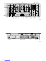 3
3
-
 4
4
-
 5
5
-
 6
6
-
 7
7
-
 8
8
-
 9
9
-
 10
10
-
 11
11
-
 12
12
-
 13
13
-
 14
14
-
 15
15
-
 16
16
-
 17
17
-
 18
18
-
 19
19
-
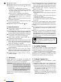 20
20
-
 21
21
-
 22
22
-
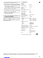 23
23
-
 24
24
-
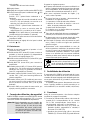 25
25
-
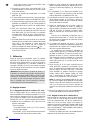 26
26
-
 27
27
-
 28
28
-
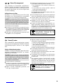 29
29
-
 30
30


IMG Stage Line 20.1670 Benutzerhandbuch
- Kategorie
- Audiomischer
- Typ
- Benutzerhandbuch
- Dieses Handbuch ist auch geeignet für
in anderen Sprachen
- français: IMG Stage Line 20.1670 Manuel utilisateur
- español: IMG Stage Line 20.1670 Manual de usuario
- italiano: IMG Stage Line 20.1670 Manuale utente