Titan PowrTwin 4900, 6900, 8900, 12000 Plus Service Manual Benutzerhandbuch
- Kategorie
- Spritzpistole
- Typ
- Benutzerhandbuch
Dieses Handbuch eignet sich auch für

POWRTWIN™
PLUS
Powered By Speeflo® HydraDrive™
0623 • Form No. 2439109G
AIRLESS, HIGH-PRESSURE
SPRAYING UNIT
AIRLESS HOCHDRUCK-
SPRITZGERÄT
GROUPE DE PROJECTION À
HAUTE PRESSION
SERVICE MANUAL
Models:
PT4900 (230V) 0290032
PT4900 (Gas) 0290012
PT6900 (Gas) 0290013
PT8900 (Gas) 0290018
PT12000 (Gas) 0290016 (Honda)
PT12000 (Gas) 0290016K (Kohler)
- GB - SERVICE MANUAL 2
- D - SERVICEHANDBUCH 16
- F - MANUEL D’ENTRETIEN 32

2 PowrTwin Plus
GB
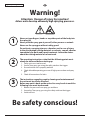
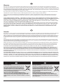
Warning!
Attention: Danger of injury by injection!
Airless units develop extremely high spraying pressures.
Be safety conscious!
1
2
3
Never put your ngers, hands or any other parts of the body into
the spray jet!
Never point the spray gun at yourself, other persons or animals.
Never use the spray gun without safety guard.
Do not treat a spraying injury as a harmless cut. In case of injury
to the skin through coating materials or solvents, consult a doctor
immediately for quick and expert treatment. Inform the doctor
about the coating material or solvent used.
The operating instructions state that the following points must
always be observed before starting up:
1. Faulty units must not be used.
2. Secure Titan spray gun using the safety catch on the trigger.
3. Ensure that the unit is properly earthed.
4. Check allowable operating pressure of high-pressure hose and spray
gun.
5. Check all connections for leaks.
The instructions regarding regular cleaning and maintenance of
the unit must be strictly observed.
Before any work is done on the unit or for every break in work the
following rules must be observed:
1. Release the pressure from spray gun and hose.
2. Secure the Titan spray gun using the safety catch on the trigger.
3. Switch o unit.
Original Operating Manual

PowrTwin Plus 1
GB
Contents
Contents
Page
1. Safety regulations for Airless spraying ...................................... 2
1.1 Explanation of symbols used .............................................................. 2
1.2 Electrical safety ......................................................................................... 3
1.3 Gasoline engine safety .......................................................................... 4
1.4 Fueling (gas engine) ............................................................................... 4
1.5 Setting up on uneven surfaces ........................................................... 4
2. Repairs ....................................................................................................... 5
2.1 Replacing the motor brushes (120V electric convertokit) ........ 5
2.2 Replacing the belt ................................................................................... 6
2.3 Servicing the hydraulic motor ............................................................ 8
2.4 Servicing the uid section ..................................................................10
2.5 SAE O-ring tting installation ...........................................................12
3. Troubleshooting .................................................................................13
3.1 Airless gun ...............................................................................................13
3.2 Fluid section ............................................................................................ 13
3.3 Hydraulic motors ...................................................................................14
3.4 Spray patterns ........................................................................................15
Accessories and spare parts ........................................................................48
Spare parts list for the main assembly .................................................. 48/49
Spare parts list for the cart assembly .................................................... 50/51
Spare parts list for the hydraulic system .............................................. 52/53
Spare parts list for the hydraulic motor ............................................... 54/55
Spare parts list for the uid section • PT4900 ..................................... 56/57
Spare parts list for the uid section •
PT6900 / PT8900 / PT12000 ...................................................................... 58/59
Spare parts list for gas convertokit ........................................................ 60/61
Spare parts list for electric convertokit (230V) ................................... 62/63
Spare parts list for the high-pressure lter ................................................64
Spare parts list for belt guard assembly ......................................................65
Spare parts list for bleed hose assembly with valve ............................... 66
Spare parts list for bleed valve .......................................................................67
Spare parts list fo siphon hose assembly ....................................................68
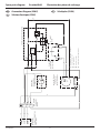
Connection diagram (230V) .........................................................................69
Accessories for PT units .................................................................................70
Gun manifold assemblies (optional) ..................................................... 72/73
Warranty ...............................................................................................................76

2 PowrTwin Plus
GB
Safety precautions
1. Safety regulations for Airless spraying
1.1 Explanation of symbols used
This manual contains information that must be read and understood
before using the equipment. When you come to an area that has one
of the following symbols, pay particular attention and make certain
to heed the safeguard.
This symbol indicates a potential hazard that
may cause serious injury or loss of life. Important
safety information will follow.
At
tention
This symbol indicates a potential hazard to you
or to the equipment. Important information that
tells how to prevent damage to the equipment or
how to avoid causes of minor injuries will follow.
Danger of skin injection
Danger of fire from solvent and paint fumes
Danger of explosion from solvent, paint fumes
and incompatible materials
Danger of injury from inhalation of harmful
vapors
i
Notes give important information which should
be given special attention.
WARNING! CALIFORNIA PROPOSITION
65 WARNING
This product can expose you to chemicals including
lead, which are known to the State of California to
cause cancer, birth defects, or other reproductive
harm.
The engine exhaust from models with gas-powered
engines can expose you to carbon monoxide which is
known to the State of California to cause cancer, birth
defects, and other reproductive harm.
For more information go to www.P65warnings.
ca.gov.
HAZARD: INJECTION INJURY
A high pressure stream produced by this equipment
can pierce the skin and underlying tissues, leading to
serious injury and possible amputation.
Do not treat a spraying injury as a harmless cut. In
case of injury to the skin through coating materials
or solvents, consult a doctor immediately for quick
and expert treatment. Inform the doctor about the
coating material or solvent used.
PREVENTION:
• NEVER aim the gun at any part of the body.
• NEVER allow any part of the body to touch the uid stream.
DO NOT allow body to touch a leak in the uid hose.
• NEVER put your hand in front of the gun. Gloves will not
provide protection against an injection injury.
• ALWAYS lock the gun trigger, shut the uid pump o and
release all pressure before servicing, cleaning the tip guard,
changing tips, or leaving unattended. Pressure will not be
released by turning o the engine. The PRIME/SPRAY valve
or pressure bleed valve must be turned to their appropriate
positions to relieve system pressure.
• ALWAYS keep tip guard in place while spraying. The tip guard
provides some protection but is mainly a warning device.
• ALWAYS remove the spray tip before ushing or cleaning the
system.
• NEVER use a spray gun without a working trigger lock and
trigger guard in place.
• All accessories must be rated at or above the maximum
operating pressure range of the sprayer. This includes spray
tips, guns, extensions, and hose.
HAZARD
: HIGH PRESSURE HOSE
The paint hose can develop leaks from wear, kinking
and abuse. A leak can inject material into the skin.
Inspect the hose before each use.
PREVENTION:
• Avoid sharp bending or kinking of the high-pressure hose. The
smallest bending radius amounts to about 20 cm.
• Do not drive over the high-pressure hose. Protect against
sharp objects and edges.
• Replace any damaged high-pressure hose immediately.
• Never repair defective high-pressure hoses yourself!
• Electrostatic charging of spray guns and the high-pressure
hose is discharged through the high-pressure hose. For this
reason the electric resistance between the connections of the
high-pressure hose must be equal to or lower than 1MΩ.
• For reasons of function, safety and durability use only original
Titan high-pressure hoses.
• Before each use, check all hoses for cuts, leaks, abrasion
or bulging of cover. Check for damage or movement of
couplings. Immediately replace the hose if any of these
conditions exist. Never repair a paint hose. Replace it with
another earthed high-pressure hose.
• Make sure power cord, air hose and spray hoses are routed in
such a manner to minimize slip, trip and fall hazard.
HAZARD: EXPLOSION OR FIRE
Flammable vapors, such as solvent and paint vapors,
in work area can ignite or explode.
PREVENTION:
• Use equipment only in well ventilated area. Keep a good
supply of fresh air moving through the area to keep the air
within the spray area free from accumulation of ammable
vapors. Keep pump assembly in well ventilated area. Do not
spray pump assembly.
• Electric models only - Do not use materials with a ashpoint
below 38º C (100º F). Flashpoint is the temperature at which a
uid can produce enough vapors to ignite.
• Gas models only - Do not ll fuel tank while engine is running
or hot; shut o engine and allow to cool. Fuel is ammable
and can ignite or explode if spilled on a hot surface.
• Eliminate all ignition sources, such as pilot lights, cigarettes,
portable electric lamps and plastic drop cloths (potential static
arc).

PowrTwin Plus 3
GB
Safety precautions
• Keep work area free of debris, including solvent, rags and
gasoline.
• Do not plug or unplug power cords, or turn power or light
switches on or o when ammable vapors are present.
• Ground equipment and conductive objects in work area.
Make sure the grounding cable (not equipped) is connected
from the grounding lug to a true earth ground.
• Use only grounded hoses.
• Hold spray gun rmly to the side of a grounded pail when
triggering into pail.
• If there is static sparking or if you feel a shock, stop operation
immediately.
• Know the contents of the paint and solvents being sprayed.
Read all Material Safety Data Sheets (MSDS) and container
labels provided with the paints and solvents. Follow the paint
and solvent manufacturer’s safety instructions.
• Do not use a paint or solvent containing halogenated
hydrocarbons. Such as chlorine, bleach, mildewcide,
methylene chloride and trichloroethane. They are not
compatible with aluminum. Contact the coating supplier
about compatibility of material with aluminum.
• Keep a re extinguisher in work area.
HAZARD: HAZARDOUS VAPORS
Paints, solvents, and other materials can be harmful
if inhaled or come in contact with body. Vapors can
cause severe nausea, fainting, or poisoning.
PREVENTION:
• Wear respiratory protection when spraying. Read all
instructions supplied with the mask to be sure it will provide
the necessary protection.
• All local regulations regarding protection against hazardous
vapors must be observed.
• Wear protective eyewear.
• Protective clothing, gloves and possibly skin protection cream
are necessary for the protection of the skin. Observe the
regulations of the manufacturer concerning coating materials,
solvents and cleaning agents in preparation, processing and
cleaning units.
HAZARD: GENERAL
This product can cause severe injury or property
damage.
PREVENTION:
• Follow all appropriate local, state, and national codes
governing ventilation, re prevention, and operation.
• Pulling the trigger causes a recoil force to the hand that is
holding the spray gun. The recoil force of the spray gun is
particularly powerful when the tip has been removed and
a high pressure has been set on the airless pump. When
cleaning without a spray tip, set the pressure control knob to
the lowest pressure.
• Use only manufacturer authorized parts. User assumes all
risks and liabilities when using parts that do not meet the
minimum specications and safety devices of the pump
manufacturer.
• ALWAYS follow the material manufacturer’s instructions for
safe handling of paint and solvents.
• Clean up all material and solvent spills immediately to prevent
slip hazard.
• Wear ear protection. This unit can produce noise levels above
85 dB(A).
• Never leave this equipment unattended. Keep away from
children or anyone not familiar with the operation of airless
equipment.
• Do not spray on windy days.
• The device and all related liquids (i.e. hydraulic oil) must be
disposed of in an environmentally friendly way.
1.2 Electric Safety
Electric models must be earthed. In the event of an electrical short
circuit, earthing reduces the risk of electric shock by providing an
escape wire for the electric current. This product is equipped with
a cord having an earthing wire with an appropriate earthing plug.
Connection to the mains only through a special feed point, e.g.
through an error protection insallation with INF < 30 mA.
DANGER — Work or repairs at the electrical
equipment may only be carried out by a skilled
electrician. No liability is assumed for incorrect
installation. Switch the unit o. Before all repair
work, unplug the power plug from the outlet.
Danger of short-circuits caused by water ingressing into the electrical
equipment. Never spray down the unit with high-pressure or high-
pressure steam cleaners.
Work or repairs at the electrical equipment:
These may only be carried out by a skilled electrician. No liability is
assumed for incorrect installation.
Operating Temperature
This equipment will operate correctly in its intended ambient, at a
minimum between +10°C and +40°C.
Relative Humidity
The equipment will operate correctly within an environment at 50%
RH, +40°C. Higher RH may be allowed at lower temperatures.
Measures shall be taken by the Purchaser to avoid the harmful eects
of occasional condensation.
Altitude
This equipment will operate correctly up to 2100 m above mean sea
level.
Transportation and Storage
This equipment will withstand, or has been protected against,
transportation and storage temperatures of -25°C to +55°C and for
short periods up to +70°C.
It has been packaged to prevent damage from the eects of normal
humidity, vibration and shock.
1.3 Gasoline Engine Safety
1. Gas engines are designed to give safe and dependable service
if operated according to instructions. Read and understand
the engine manufacturer’s Owner’s Manual before operating
the engine. Failure to do so could result in personal injury or
equipment damage.
2. To prevent re hazards and to provide adequate ventilation,
keep the engine at least 1 meter (3 feet) away from buildings
and other equipment during operation. Do not place
ammable objects close to the engine.
3. People who are not operating the device must stay away from
the area of operation due to a possibility of burns from hot
engine components or injury from any equipment the engine
may be used to operate.
4. Know how to stop the engine quickly, and understand the
operation of all controls. Never permit anyone to operate the
engine without proper instructions.
5. Gasoline is extremely ammable and is explosive under
certain conditions.
6. Refuel in a well-ventilated area with the engine stopped. Do
not smoke or allow ames or sparks in the refueling area or
where gasoline is stored.

4 PowrTwin Plus
GB
Safety precautions
7. Do not overll the fuel tank. After refueling, make sure the
tank cap is closed properly and securely.
8. Be careful not to spill fuel when refueling. Fuel vapor or
spilled fuel may ignite. If any fuel is spilled, make sure the area
is dry before starting the engine.
9. Never run the engine in an enclosed or conned area. Exhaust
contains poisonous carbon monoxide gas; exposure may
cause loss of consciousness and may lead to death.
10. The muer becomes very hot during operation and remains
hot for a while after stopping the engine. Be careful not to
touch the muer while it is hot. To avoid severe burns or re
hazards, let the engine cool before transporting it or storing it
indoors.
11. Never ship/transport sprayer with gasoline in the tank.
DO NOT use this equipment to spray water or acid.
Attention
Do not lift by cart handle when loading or unloading.
Device is very heavy. Three-person lift is required.
1.4 Fueling (gas engine)
Gasoline is extremely flammable and is explosive
under certain conditions.
Attention
Do not overll the gas tank. Overlling can cause
the gas cap to become clogged with any particles
in the gasoline which can cause a vaccum. Read
the gas engine’s instruction manual for fueling
instructions.
Fuel Specications
• Use automotive gasoline that has a pump octane number of
86 or higher, or that has a research octane number of 91 or
higher. Use of a lower octane gasoline can cause persistent
“pinging” or heavy “spark knock” (a metallic rapping noise)
which, if severe, can lead to engine damage.
iIf “spark knock” or “pinging” occurs at a steady
engine speed under normal load, change brands of
gasoline. If spark knock or pinging persists, consult
an authorized dealer of the engine manufacturer.
Failure to do so is considered misuse, and damage
caused by misuse is not covered by the engine
manufacturer’s limited warranty.
Occasionally you may experience light spark knock
while operating under heavy loads. This is no
cause for concern, it simply means your engine is
operating eciently.
• Unleaded fuel produces fewer engine and spark plug deposits
and extends the life of the exhaust system components.
• Never use stale or contaminated gasoline or an oil/gasoline
mixture. Avoid getting dirt, dust, or water in the fuel tank.
Gasolines Containing Alcohol
If you decide to use a gasoline containing alcohol (gasohol), be
sure its octane rating is at least as high as that recommended by
the engine manufacturer. There are two types of “gasohol”: one
containing ethanol, and the other containing methanol. Do not use
gasohol that contains more than 10% ethanol. Do not use gasoline
containing methanol (methyl or wood alcohol) that does not also
contain co-solvents and corrosion inhibitors for methanol. Never
use gasoline containing more than 5% methanol, even if it has co-
solvents and corrosion inhibitors.
iFuel system damage or engine performance
problems resulting from the use of fuels that contain
alcohol is not covered under the warranty. The
engine manufacturer cannot endorse the use of
fuels containing methanol since evidence of their
suitability is incomplete at this time.
Before buying gasoline from an unfamiliar station, try
to nd out if the gasoline contains alcohol. If it does,
conrm the type and percentage of alcohol used. If
you notice any undesirable operating characteristics
while using a gasoline that contains alcohol, or one
that you think contains alcohol, switch to a gasoline
that you know does not contain alcohol.
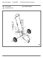
1.5 Setting up on uneven surfaces
The front side of the unit must point downwards to prevent sliding
away.

PowrTwin Plus 5
GB
Repairs
2. Repairs
Prior to making any repairs, make sure to perform
the Pressure Relief Procedure, section 4.6 of the
Operation Manual. Additionally, follow all other
warnings to reduce the risk of an injection injury,
injury from moving parts or electric shock. Always
unplug the sprayer before servicing!
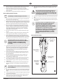
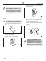
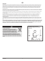
2.1 Replacing the Motor Brushes (optional 120V
electric motor)
The 120V electric Convertokit is available for separate purchase.
Perform this procedure using Motor Brush Kit P/N 978-050. The kit
consists of two brushes, two springs, and two clips.
iBrushes should be replaced when they are worn to
less than 1/2 inch. Check and replace both brushes
at the same time.
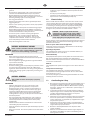
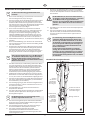
1. Remove both inspection covers (1) on the motor.
1
2. Push in the spring clip (2) to unhook it, then pull it out.
3. Loosen the terminal screw (3). Pull the brush lead (4) away,
but leave the motor lead in place. Remove the brush and
spring.
3
2
4
4. Inspect the commutator (5) for burning, excessive pitting or
gouging. A black color on the commutator is normal.
5
5. Install the new brush (6) so its lead slides in the long slot of the
brush holder (7). Push the terminal under the terminal screw
washer (8). Ensure the motor lead is still connected at the
screw. Tighten the screw.
6. Place the spring (9) on the brush (6) as shown above. Push
in and hook the spring clip (2). Repeat this procedure for the
other side.
6
7
8
9
2
7. Reinstall both inspection covers.
If electric motor overloads and stops running,
IMMEDIATELY turn the motor off and follow
the Pressure Relief Procedure in the Cleanup
section of this manual. Wait until the motor cools
(approximately 30 minutes). Then push in the
bubble top, manual reset button, turn the motor on
and pressurize the system.

6 PowrTwin Plus
GB
Repairs
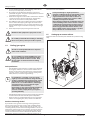
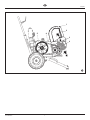
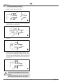
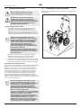
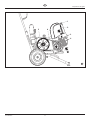
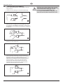
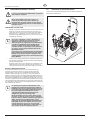
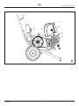
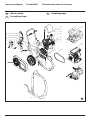
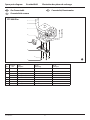
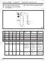
2.2 Replacing the Belt (Fig. 21)
Before replacing the belt on your unit, make sure
you have performed the “Pressure Relief Procedure”
as illustrated in the Operation section of this manual.
DO NOT attempt this repair while the unit is running.
iThe graphics below show a unit with a gas engine.
All instructions given in this section will apply to
both gas engine models and electric motor models
except where noted.
1. Loosen the bolt (1) on the front of the belt guard. Lift open
the front end of the belt guard (2) so that the front end of the
belt (3) is exposed.
2. Gently lift the front end of the gas engine / electric motor.
This will loosen the tension on the belt and make it easier to
remove.
PINCH HAZARD. Make sure your fingers remain clear
of the gas engine / electric motor mounting plate.
BURN HAZARD. Make sure the gas engine has had
time to sufficiently cool before touching it.
3. While the gas engine / electric motor is lifted up, remove the
belt from the front (4) and rear (5) pulleys.
4. Install the new belt:
a. Insert the belt into the xed section of the belt guard (6). Loop
the belt over the rear pulley (5) until the belt engages the
pulley groove.
b. Gently lift the front end of the gas engine / electric motor.
c. With the front end of the gas engine / electric motor lifted, loop
the other end of the belt around the front pulley (4).
d. Gently set the the gas engine / electric motor down. The
weight of the gas engine / electric motor will create tension in
the belt and prevent it from coming o.
Attention
Make sure the belt is not pinched or twisted in any
way once you have set the gas engine / electric
motor back into place.
e. Close the belt guard (2) and tighten the belt guard bolt (1).

5 6
1
2
4
3
PowrTwin Plus 7
GB
Repairs

8 PowrTwin Plus
GB
Repairs
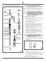
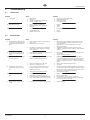
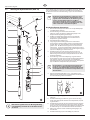
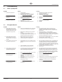
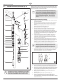
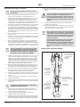
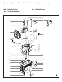
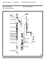
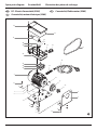
2.3 Servicing the Hydraulic Motor (Fig. 22)
1
2
3
5
6
7
4
8
14
15
16
17
18
19
9
12
13
10
11
28
29
9
30
31
20
21
26
22
23
24
25
21
(B)
(A)
iRefer to the ”SAE O-Ring Fitting Installation”
procedure at the end of this section for installation
instructions for item 22 and 24.
Perform this procedure using the necessary parts from Motor Service
Kit — Minor (P/N 235-050). If the hydraulic motor is operable, start
the machine and jog the piston rod (19) into its top position.
iServicing of the hydraulic motor should be carried
out in a clean, dust free area only. Any dust or
metallic particles left in the motor or entering it on
reassembly may damage the critical parts and aect
its service life and warranty. All parts should be
inspected for absolute cleanliness.
Disassembling the Hydraulic Motor
1. Disconnect the pressure hose assembly (B) from the elbow on
the back of the hydraulic pump.
2. Remove the two mounting screws and two lock washers that
attach the motor/pump assembly to the cart.
3. Place the motor/pump assembly in a vise, holding it securely
by the motor/pump block (31).
4. Remove cylinder head plug (1).
5. Loosen lock ring (28) with a spanner wrench and unthread
tube retaining nut on tee (24). Loosen tube retaining nut
on elbow (22). Slide the nut down. Remove motor tube
assembly (23). Slowly unthread cylinder head (8) and Iift it just
high enough above the cylinder (29) to reach the valve rod
assembly (18) with vise grip pliers.
6. The piston rod (19) should be near the top of its stroke for
disassembly. It may be necessary to use a wood or nylon driver
to push the piston rod up to its top position.
7. Grip the valve rod securely with vise grip pliers and then
remove the FlexLoc nut (3) from the top of the valve rod
assembly (18). Be careful that spool (10) does not fall. The
cylinder head (8) can now be lifted o. Unthread the cylinder
(29) from the motor/pump block (31).
iAn extra lock ring (28) can be used to jam the two
lock rings together on the cylinder and a pipe
wrench can be used to unthread the cylinder (29)
from the motor/pump block.
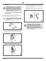
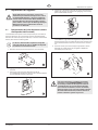
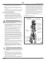
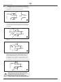
8. To remove the connecting pin (Fig. 23, 1), slide the retaining
ring (2) down with a small screwdriver, and then push the
connecting pin out.
1
2
9. Remove the piston rod assembly from the motor/pump block
(31).
10. Remove rod seal (30), being extremely careful not to scratch
the seal groove in the motor/pump block (31).
11. Place the piston retainer screw (14) on the piston rod assembly
in a vise. Slide a long bar through the hole at the base of the
piston rod for leverage, and unthread the piston rod from the
piston retainer screw.
12. Remove piston (19) and lift out valve rod assembly (18).
13. Remove piston seal (16) and o-ring (17).

PowrTwin Plus 9
GB
Repairs
14. Remove trip retainers (4), trip springs (6), and balls (7) from
cylinder head (8). Remove o-rings (5) from trip retainers.
15. Remove retaining ring (13) and sleeve retainer (12). Gently tap
spool/sleeve set (10) out of cylinder head (8) using a wood or
nylon rod.
16. Inspect piston rod (19) and cylinder (29) for wear, scratches,
and dents. Replace if damaged.
17. Inspect spool valve (10) for wear. Replace if necessary. spool
valve should move smoothly and freely with no force by
holding in a vertical position. If it does not, it can cause the
motor to stall.
Reassembling the Hydraulic Motor
1. Separate spool/sleeve set (10). Place o-rings (11) onto sleeve.
Lubricate o-rings with hydraulic oil. Gently push the sleeve
into cylinder head (8) with the atter side of the sleeve facing
out. Use a nylon rod to tap sleeve down until it reaches its full
depth. Do not use any other type of tool that might damage
or leave particles or residue on the sleeve. Install the spool
through the top of the cylinder head, down into the sleeve.
Attention
Do not use Piston Lube pump packing lubricant. It is
a solvent and will severely damage seals and O-Rings
of the hydraulic motor.
2. Install o-rings (5) on trip retainers (4). Install trip retainer balls
(7) followed by springs (6) which, when installed, will hold
spool/sleeve set (10) in proper place for assembly.
3. Install sleeve retainer (12) followed by retainer ring (13) into
cylinder head (8), which will hold valve sleeve in place. Install
o-ring (9) in the o-ring groove of the cylinder head.
4. Replace rod seal (30) in motor/pump block (31). Be sure the
open portion of the seal is facing upward (V). This seal requires
no special tool.
5. Place piston rod (19) in vise. Inspect valve rod assembly (18)
for any damage. Make sure the lock nut at the bottom of the
valve rod assembly is secure. DO NOT remove. Then, place into
piston rod as illustrated. Install o-ring (17), lubricating it well
and replacing piston (15) onto piston rod (19). Put one drop of
blue Loctite on the piston retainer screw (14). Tighten piston
retainer screw until piston is locked into place. Check valve rod
assembly for normal spring action at this time.
6. Install piston seal (16) with lips facing downward. Carefully
install o-ring (17). Expand the ring and stretch it suciently for
installation.
7. With motor/pump block (31) still in vise, install rod seal (30)
by pushing it towards its groove with a properly sized blunt
rod. Then complete installation with the ngers. No tool is
necessary. Do not twist the seal.
8. Pre-lubricate the piston and valve rod assembly with Coolo™
hydraulic uid (P/N 430-361). Install piston rod (19) into
motor/pump block (31) with a gently pushing and rotating
motion to work the piston rod in through the rod seal (30).
i
Inspect the bottom of piston rod (19) for nicks or
sharp areas that could damage the piston seal during
installation through the motor/pump block (31).
9. Replace the connecting rod pin and retainer ring.
10. Install o-ring (9) on cylinder wall. Lubricate ring and inner wall.
With the piston rod held rmly, the cylinder should be gently
driven over the piston seal with a rubber mallet. Tightly thread
the cylinder into motor/pump block (31).
11. Raise piston rod (19) to top position and thread lock ring (28)
all the way up on upper threads of cylinder (29).
12. Pull valve rod assembly (18) up as far as it will travel and grasp
it with vise grip pliers. Then install cylinder head (8), already
assembled, over valve rod until the top threads of the valve
rod pass through the top of the spool/sleeve set (10). The
valve rod threads must be clean and free of oil. Place one drop
of blue Loctite on threads of ex lock nut (3) and thread nut
onto valve rod to full tight position (do not over-tighten) while
holding valve rod below with vise grip pliers.
13. Thread cylinder head (8) down onto the cylinder (29) and
then back o just enough to reassemble hydraulic ttings and
motor tube (23). Tighten lock ring with spanner wrench to
hold cylinder head in position.
14. Install o-ring (2) onto cylinder head plug (1). Tighten.
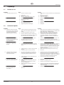
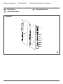
Hydraulic Motor Cut-Away
Use blue
Loctite on
lock ring.
Use
hydraulic
sealant.
Seal lip must
face up.
Torque ex locknut to
40 in.-lbs. (4.5 Nm).
Use blue Loctite.
Torque head plug to
15 ft.-lbs. (22 Nm).
Do not over-tighten
o-ring seal.
Torque trip
retainers to
8 ft.-lbs. (10.8 Nm).
Do not over-tighten
o-ring seal.
Torque piston
retainers to
40 ft.-lbs. (55 Nm).
Use red Loctite.
Seal lip must
face down.
Valve rod assembly
is factory set and
permanently Loctited.
Do not disassemble.

10 PowrTwin Plus
GB
Maintenance
Attention
Use of non-Titan service parts may void warranty.
Ask for original parts made by Titan for best services.
This pump should receive a routine servicing after
approximately 1,000 hours of use. Earlier servicing
is required if there is excessive leakage from the top
packing or if pump strokes become faster on one
stroke or the other. The use of Titan Piston Lube
(P/N 314-480) is recommended as an upper packing
lubricant. Do not substitute oil, water, or solvent for
an upper packing lubricant.
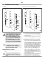
i
Numbers in parentheses refer to the item numbers
in the fluid section illustrations. If there are two
numbers, the first number represents the item
number for the PT4900 Plus and the second number
represents the item number for the PT6900 Plus /
PT8900 Plus / PT12000 Plus.
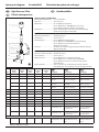
Disassembling the Fluid Section
1a. Remove the siphon hose assembly. Unthread the foot valve
housing (20,21) and the pump cylinder (14) with a strap
wrench.
iIf the pump cylinder (14) cannot be removed with a
strap wrench, use the removal nut (23, 22) to remove
it from the pump housing.
1b. Loosen the removal nut (23, 22) on the cylinder until it
bottoms out on the cylinder threads. Place a wrench on the
ats of the removal nut and turn the wrench counterclockwise
to loosen the cylinder.
2. Slide the retainer ring (1) up with a small screwdriver, then
push the connecting pin (2) out.
3. Pull the displacement rod (6) through the lower cavity of the
motor/pump block.
4. Remove the PTFE o-ring (3), upper packing spring (5), and
upper packing set (4) from the motor/pump block.
5. Hold the displacement rod (6) in a vise by the ats at the top
of the displacement rod and remove the outlet valve housing
(13) with a wrench while holding the displacement rod
horizontal with wooden support, if necessary. Remove the
seal washer (12), outlet valve seat (11), outlet valve ball (10),
outlet valve cage (9, PT6900/PT8900/PT12000) lower packing
set (4), lower packing spring (9,8), sleeve (8, PT4900 only), and
spring retainer (7, PT4900 only).
6. Using a 1/2” extension bar attached to a 1/2” drive ratchet,
insert the end of the extension bar into the square opening
of the foot valve cage (16,17) inside the foot valve housing
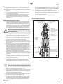
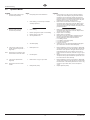
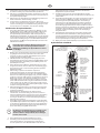
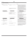
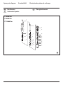
2.4 Servicing the Fluid Section
6
7
8
9
13
10
11
12
14
23
15
16
17
18
19
3
21
20
1
2
5
4
4
3
6
8
9
13
10
11
12
14
22
15
16
17
18
19
20
3
21
1
2
5
44
3
PT4900 Plus PT6900 Plus / PT8900 Plus / PT12000 Plus

PowrTwin Plus 11
GB
Maintenance
(20,21). Unscrew and remove the foot valve cage along with
the wave washer (21,16) from the foot valve housing.
7. Remove the PTFE o-ring (3), foot valve ball (17,18), foot
valve seat (18,19), and seat o-ring (19,20) from the foot valve
housing (20,21).
8. Remove the o-ring (15) from the pump cylinder (14)
Reassembling the Fluid Section
i
Use PTFE tape on all threaded pipe connections.
1. Place a new seat o-ring (19,20) into the groove in the bottom
of the foot valve housing (20,21).
2. Inspect the foot valve seat (18,19) for wear. If one side is worn,
ip the seat to the unused side. If both sides are worn, install a
new seat. Place the new or ipped seat (worn side down) into
the bore at the bottom of the foot valve housing (20,21).
3. Place a new foot valve ball (17,18) onto the foot valve seat
(18,19). Using a 1/2” extension bar attached to a 1/2” drive
ratchet, insert the end of the extension bar into the square
opening of the foot valve cage (16,17) and screw the foot
valve cage into the foot valve housing (20,21). Torque the
cage to 240 in./lbs. (20 ft./lbs.).
4. Place the wave washer (21, 16) on top of the foot valve cage
(16,17).
5. Insert a new PTFE o-ring (3) into the groove of the foot valve
housing (20,21). Lubricate the o-ring using oil or grease.
6. After soaking the leather packings in oil (preferably linseed
oil), reassemble the lower packing set (4). Place the set onto
the outlet valve housing (13) with the peak of the “V” packings
pointing down toward the hex on the outlet valve housing.
iAll leather packings must be soaked in CoolFlo
hydraulic oil for 15–20 minutes before installation.
Soaking the packings too long will cause the
packings to swell and create diculty during
reassembly.
7. Inspect the outlet valve seat (11) for wear. If one side is worn,
ip the seat to the unused side. If both sides are worn, use
a new seat. Insert the outlet valve cage (9, PT6900/PT8900/
PT12000) outlet valve ball (10), new or ipped seat (worn
side away from ball), and a new seal washer (12) into the
displacement rod (6).
8. Clean the threads on the outlet valve housing (13) and coat
the threads with blue Loctite #242. Make sure the Loctite is
only on the threads.
9. Place the lower packing spring (9,8) onto the outlet valve
housing (13) followed by the sleeve (8, PT4900 only) and
spring retainer (7, PT4900 only).
10. Screw the displacement rod (6) and the outlet valve housing
(13) together. Tighten in a vise to 600 in./lbs. (50 ft./lbs.).
11. Insert the PTFE o-ring (3) into the upper grove of the motor/
pump block.
12. Insert the upper packing set (4) into the motor/pump block
with the peak of the “V” packings pointing up toward the
motor.
i
The packings must be soaked in CoolFlo hydraulic oil
before installation.
13. Place the upper packing spring (5) into the motor/pump block
with the small tapered end facing up toward the motor/pump
block.
14. Insert the displacement rod (6) up through the upper packings
in the motor/pump block.
15. Align the holes in the displacement rod (6) and the hydraulic
piston rod and insert the connecting pin (2). Replace the
retaining ring (1) over the connecting pin.
16. Orient the cylinder (14) with the knurled portion and removal
nut at the top, thread into the block and tighten with a strap
wrench.
Attention
The removal nut (23) must be kept bottomed out
on the threads after the cylinder is tight. Do not
use the nut to jam against the block or damage will
occur during use. This nut is to be used to help with
removing the cylinder only.
17. Place the o-ring (15) onto the top groove of the pump cylinder
(14).
18. Thread the foot valve housing (20,21) onto the pump cylinder
(14), tighten with a strap wrench and then back o to align the
siphon hose.
iIt is not necessary to over-tighten the foot valve
housing. O-ring seals perform sealing function
without excessive tightening. Full thread
engagement is sufficient. The foot valve housing
may be rotated backward up to 1/2 turn from full
engagement for convenient hose position.
For siphon hose attachment, it is critically important
that the threads of the siphon hose fit snugly into
the foot valve housing with the hose assembly
couplings PTFE taped and sealed to prevent air
leakage.
Fluid Section Cut-Away
Peaks of upper
packings must
face up.
Torque outlet
valve housing
to 50 ft./lbs.
(68 Nm).
Use blue
Loctite.
Oil cup area
for piston lube
packing
lubricant.
Peaks of lower
packings must
face down.
Lubricate O-ring.

12 PowrTwin Plus
GB
Maintenance
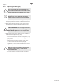
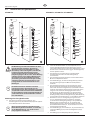
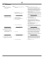
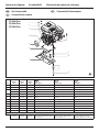
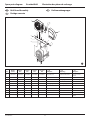
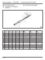
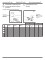
2.5 SAE O-Ring Fitting Installation
1. Pull washer and o-ring back as far as possible.
2. Lubricate o-ring (1) and entrance port (2).
1
2
3. Screw tting in until washer pushes o-ring into entrance and
sits at against port. (Do not tighten! - only do this step hand
tight to compress o-ring into port!)
4. Back tting out no more than one complete turn to align as
required.
5. Torque nut wrench tight holding backup on tting (3). This
should expose a recess gap (4) behind the nut which can act
as an indicator that the tting is assembled correctly. (This is a
feature for a specic version of this tting only - which screws
into the cylinder head. Other ttings, as the ones which attach
to the hydraulic pump, assemble the same but may not have
the indicator.)
4
3
Attention
Avoid screwing in the fitting too far. This can cause
the washer to bend, which will cause the O-ring to
extrude.
Avoid leaving the fitting out too far. This can lead to
the O-ring being cut on the threads of the fitting.

PowrTwin Plus 13
GB
Troubleshooting
Problem
A. Spitting gun
B. Gun will not shut o
C. Gun does not spray
Problem
A. Pump delivers on upstroke only
or goes up slowly and down fast
(commonly called downstroke
dive)
B. Pump delivers on down stroke
only or goes up fast and down
slowly
C. Pump moves up and down fast,
delivering material
D. Pump moves up and down
slowly when spray gun is shut
o
E. Not enough uid pressure at
gun
F. Pump chatters on up or down
stroke
Cause
1. Air in system
2. Dirty gun
3. Needle assembly out of adjustment
4. Broken or chipped seat
1. Worn or broken needle & seat
2. Needle assembly out of adjustment
3. Dirty gun
1. No paint
2. Plugged lter or tip
3. Broken needle in gun
Cause
1. Lower foot valve ball is not seating due to
trash or wear
2. Material too viscous to siphon.
3. Air leaking in on siphon side or damaged
siphon hose. Siphon may be too small for
heavy material.
1. Upper ball is not seating due to trash or wear
2. Lower packing set is worn
1. Material container is empty or material is too
thick to ow through siphon hose
2. Bottom ball stuck to foot valve seat
3. Siphon hose is kinked or loose
1. Loose connections. Bleed valve is open
partially or bleed valve is worn. Lower
packing seat is worn.
2. Upper and/or lower ball not seating
1. Spray tip is worn
2. Outlet lter or gun lter is clogged
3. Low voltage and/or inadequate amperage
4. Hose size or length is too small or too long
1. Solvent has caused upper packing to swell
Solution
1. Inspect connections for air leaks.
2. Disassemble and clean.
3. Inspect and adjust.
4. Inspect and replace.
1. Replace.
2. Adjust.
3. Clean.
1. Check uid supply.
2. Clean.
3. Replace.
Solution
1. Remove foot valve assembly. Clean and inspect. Test
foot valve by lling with water; if ball fails to seal the
seat, replace ball.
2. Thin material — contact manufacturer for proper
thinning procedures.
3. Tighten all connections between pump and paint
container. If damaged, replace. Switch to larger diameter
siphon set.
1. Check upper seat and ball with water. If ball fails to seal,
replace seat.
2. Replace packing set if worn.
1. Rell with new material. If too thick, remove siphon
hose, immerse uid section in material, and start pump
to prime. Add thinner to material. Change to bigger
siphon set. Open bleed valve to remove air and restart
pump.
2. Remove foot valve. Clean ball and seat.
3. Straighten.
1. Check all connections between pump and gun. Tighten
as necessary. If material is owing from bleed hose, close
bleed valve or replace, if necessary. Should none of the
above be evident, replace lower packing.
2. Reseat balls by cleaning.
1. Replace.
2. Clean or replace lter.
3. Check electrical service. Correct as required.
4. Increase hose size to minimize pressure drop through
hose and/or reduce hose length.
1. Replace packing.
3. Troubleshooting
3.1 Airless Gun
3.2 Fluid Section

14 PowrTwin Plus
GB
Troubleshooting
Problem
A. Oil motor stalls at bottom (no
unusual heat problems)
B. Oil motor stalls at top (no
unusual heat problems)
C. Low pressure (okay on down
stroke, sluggish on up.stroke —
high heat)
Note: Engine labors on upstroke, idles
back at stall on the down stroke.
D. Low pressure (both strokes -
high heat)
Note: Engine labors at stall on both
strokes.
Cause
1. Fluid pump piston seat unthreaded
2. Valve sticking or oil motor trip rod shifter
assembly separated
1. Valve sticking
2. Broken spring retainer (valve rod assembly)
3. Broken spring or valve rod
4. Air in hydraulic motor
5. Air in uid pump
1. Blown piston seal
2. Cracked piston
1. Blown center o-rings on spool valve
2. Bad hydraulic pump
Solution
1. If connecting rod is okay, remove cylinder head plug
and pop valve down. Replace plug and start machine.
If machine cycles up and stops at bottom again, then
problem is piston seat on uid pump. Check piston seat.
Repair or replace as necessary. If piston seat is okay and
problem does not change, check oil motor.
2. Remove valve and check for scratches and rough
movement when sliding it up and down. Replace valve
and spool in this condition. Check trip rod for possible
separation.and spool in this condition. Check trip rod for
possible separation.
1. Remove valve and check for scratches and rough
movement when sliding it up and down. Replace valve
and spool in this condition.
2. Replace valve rod assembly.
3. Replace valve rod assembly.
4. Reset valve. Purge Air, generally accomplished by low
pressure cycling of motor/pump assembly for 5–10
minutes. Check for causes of air introduction:
• Loose ttings in tank.
• Loose ttings on hydraulic pump.
• Loose hose connections.
• Low oil in reservoir.
5. Stall at top can occur randomly when uid pump picks
up air. Reset valve. Avoid air in the uid pump.
1. Before dismantling oil motor, start machine. With pump
cycling under pressure, touch the hydraulic cylinder and
the head to see if cylinder or head gets hotter. This will
help determine if piston seal is blown or piston nut is
broken. If heat is on the head, check the o-rings on spool
valve.
2. Dismantle oil motor and check piston seals cylinder bore
and piston nut. Pay special attention to piston nut. It can
be cracked and not show externally.
1. Before dismantling oil motor, start machine. With pump
cycling under pressure, touch the head to see if the head
becomes hotter. This will help determine if center o-ring
is blown on spool valve. If hot, remove and replace
o-ring.
2. Replace hydraulic pump.
3.3 Hydraulic Motors

PowrTwin Plus 15
GB
Troubleshooting
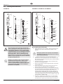
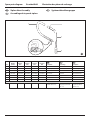
Problem
A. Tails
B. Hour glass
C. Distorted
D. Pattern expanding and
contracting (surge)
E. Round pattern
Cause
1. Inadequate uid delivery
1. Inadequate uid delivery
1. Plugged or worn nozzle tip
1. Suction leak
2. Pulsating uid delivery
1. Worn tip
2. Fluid too heavy for tip
Solution
1. Fluid not atomizing correctly:
Increase uid pressure. Change to smaller tip orice size.
Reduce uid viscosity. Reduce hose length. Clean gun
and lter(s). Reduce number of guns using pump.
1. Same as above.
1. Clean or replace nozzle tip.
1. Inspect for suction hose leak.
2. Change to a smaller tip orice size. Install pulsation
dampener in system or drain existing one. Reduce
number of guns using pump. Remove restrictions in
system; clean tip screen if lter is used.
1. Replace tip.
2. Increase pressure. Thin material. Change nozzle tip.
3.4 Spray Patterns

16 PowrTwin Plus
D
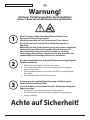
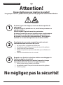
Warnung!
Achtung: Verletzungsgefahr durch Injektion!
Airless-Geräte entwickeln extrem hohe Spritzdrücke.
Achte auf Sicherheit!
1
2
3
Niemals Finger, Hände oder andere Körperteile mit dem
Spritzstrahl in Berührung bringen!
Nie die Spritzpistole auf sich, Personen und Tiere richten.
Nie die Spritzpistole ohne Spritzstrahl-Berührungsschutz
benutzen.
Behandeln Sie eine Spritzverletzung nicht als harmlose Schnittver-
letzung. Bei einer Hautverletzung durch Beschichtungssto
oder Lösemittel sofort einen Arzt aufsuchen zur schnellen,
fachkundigen Behandlung. Informieren Sie den Arzt über den
verwendeten Beschichtungssto oder das Lösemittel.
Vor jeder Inbetriebnahme sind gemäß Betriebsanleitung folgende
Punkte zu beachten:
1. Fehlerhafte Geräte dürfen nicht benutzt werden.
2. Titan-Spritzpistole sichern mit Sicherungshebel am Abzugsbügel.
3. Erdung sicherstellen.
4. Zulässigen Betriebsdruck von Hochdruckschlauch und Spritzpistole
überprüfen.
5. Alle Verbindungsteile auf Dichtheit prüfen.
Anweisungen zur regelmäßigen Reinigung und Wartung des
Gerätes sind streng einzuhalten.
Vor allen Arbeiten am Gerät und bei jeder Arbeitspause folgende
Regeln beachten:
1. Spritzpistole und Hochdruckschlauch druckentlasten.
2. Titan-Spritzpistole sichern mit Sicherungshebel am Abzugsbüge.
3. Gerät ausschalten.
Übersetzung der Originalbetriebsanleitung

PowrTwin Plus 17
D
Inhalt Sicherheitsvorschriften
Inhalt
Seite
1. Sicherheitsvorschriften für das Airless-Spritzen .................17
1.1 Erklärung der verwendeten Symbole ............................................ 17
1.2 Elektrische Sicherheit ...........................................................................18
1.3 Benzinmotoren-Betriebssicherheit .................................................19
1.4 Betanken (Benzinmotor) .....................................................................20
1.5 Aufstellung in unebenem Gelände.................................................20
2. Reparaturen am gerät ......................................................................21
2.1 Auswechseln der Motorbürsten
(optional 120 V elektrischer Motor) ................................................ 21
2.2 Auswechseln des Riemens .................................................................22
2.3 Wartung des Hydraulikmotors ......................................................... 24
2.4 Unterhalt des Flüssigkeitsbereiches ...............................................26
2.5 Montageanleitung zum SAE O-Ring ..............................................28
3. Fehlerbehebung ..................................................................................29
3.1 Airless-Spritzpistole .............................................................................. 29
3.2 Flüssigkeitsbereich ...............................................................................29
3.3 Hydraulikmotor ......................................................................................30
3.4 Spritzmuster ............................................................................................ 31
Zubehör und Ersatzteile ................................................................................ 48
Ersatzteilliste Hauptbaugruppe .............................................................. 48/49
Ersatzteilliste Wagen ................................................................................... 50/51
Ersatzteilliste Hydrauliksystem ................................................................ 52/53
Ersatzteilliste Hydraulikmotor ................................................................. 54/55
Ersatzteilliste Flüssigkeitsbereich • PT4900 ......................................... 56/57
Ersatzteilliste Flüssigkeitsbereich •
PT6900 / PT8900 / PT12000 ...................................................................... 58/59
Ersatzteilliste Convertokit, Benzinmotor ............................................. 60/61
Ersatzteilliste Convertokit, Elektromotor (230V) ............................... 62/63
Ersatzteilliste Hochdrucklter .........................................................................64
Ersatzteilliste Keilriemenbaugruppe ............................................................ 65
Ersatzteilliste Ablassschlauchbaugruppe mit Ventil ..............................66
Ersatzteilliste Ablassschlauchbaugruppe ...................................................67
Ersatzteilliste Syphonschlauchbaugruppe ................................................68
Schaltplan (230V) ..............................................................................................69
Zubehör für PT-Geräte ...................................................................................70
Pistolenmehrfachanschluss (Optional) ................................................ 72/73
Garantie .................................................................................................................76
1. Sicherheitsvorschriften für das Airless-
Spritzen
1.1 Erklärung der verwendeten Symbole
Diese Bedienanleitung enthält Informationen, die der Benutzer vor
Verwendung des Geräts gründlich durcharbeiten muss. In Bereichen,
die mit den folgenden Symbolen gekennzeichnet sind, besonders
vorsichtig arbeiten und alle Sicherheitshinweise beachten.
Dieses Symbol verweist auf eine potenzielle
Gefahr, die zum Tode oder zu schweren
Verletzungen führen kann. Hier finden Sie
wichtige Sicherheitsinformationen.
Achtung
Dieses Symbol weist auf eine potenzielle Gefahr
für Sie bzw. das Gerät hin. Unter diesem Symbol
finden Sie wichtige Informationen, wie Sie
Schäden an dem Gerät und Verletzungsgefahr
vermeiden.
Injektionsgefahr
Brandgefahr durch Lösemittel und Farbdämpfe
Explosionsgefahr durch Lösemittel, Farbdämpfe
und ungeeignete Materialien
Verletzungsgefahr durch das Einatmen von
schädlichen Dämpfen
i
Hinweise enthalten wichtige Informationen, die
beachtet werden sollten.
GEFAHR: Verletzung durch Flüssigkeiten
unter Druck
Eine unter hohem Druck stehende Flüssigkeit,
wie sie von diesem Gerät erzeugt wird, kann die
Haut durchdringen und in das darunter liegende
Bindegewebe eindringen und so zu schweren
Verletzungen und selbst zur Amputation führen.
Behandeln Sie eine Spritzverletzung nicht
als harmlose Schnittver-letzung. Bei einer
Hautverletzung durch Beschichtungssto oder
Lösemittel sofort einen Arzt aufsuchen zur schnellen,
fachkundigen Behandlung. Informieren Sie den
Arzt über den verwendeten Beschichtungssto oder
das Lösemittel.
VORSICHTSMASSNAHMEN:
• NIEMALS die Spritzpistole auf Körperteile halten.
• NIEMALS mit Körperteilen den Flüssigkeitsstrahl berühren.
NIEMALS mit dem Körper eine Leckstelle im Druckschlauch
berühren.
• NIEMALS die Hand vor die Düse der Spritzpistole halten.
Handschuhe stellen keinen sicheren Schutz vor Verletzungen
durch injizierte Flüssigkeiten dar.
• STETS den Auslöser der Spritzpistole verriegeln, die Pumpe
ausschalten und den Druck vollständig entspannen,
bevor Wartungs- und Reinigungsarbeiten, Durchsichten,
Düsenwechsel oder ähnliche Arbeiten durchgeführt werden
oder das Gerät unbeaufsichtigt gelassen wird. Auch nach
dem Ausschalten des Motors steht das Gerät noch unter

18 PowrTwin Plus
D
Sicherheitsvorschriften
Druck. Das Ventil PRIME/SPRAY (Vorfüll-/Sprühventil) bzw.
das Druckentlastungsventil müssen in ihren Sollpositionen
stehen, um den Systemdruck zu entspannen.
• STETS den Düsenschutz aufsetzen, wenn Spritzarbeiten
durchgeführt werden. Der Düsenschutz stellt einen gewissen
Schutz dar, ist aber vor allem als Warnvorrichtung gedacht.
• STETS die Spritzdüse entfernen, bevor das System gereinigt
oder gespült wird.
• NIEMALS eine Spritzpistole ohne funktionsfähige
Auslöserverriegelung und ohne Auslöserbügel verwenden.
• Das gesamte Zubehör muss mindestens für den maximalen
Betriebsdruckbereich des Spritzgeräts zugelassen sein. Dazu
gehören Spritzdüsen, Spritzpistolen, Verlängerungen und
Schlauch.
GEFAHR: Hochdruckschlauch
Durch Verschleiß, Knicken und nicht
zweckentsprechende Verwendung können sich
Leckstellen im Farbschlauch bilden. Durch eine
Leckstelle kann Flüssigkeit in die Haut injiziert
werden. Vor Verwendung den Schlauch gründlich
prüfen.
VORSICHTSMASSNAHMEN:
• Scharfes Biegen oder Knicken des Hochdruckschlauches
vermeiden, kleinster Biegeradius etwa 20 cm.
• Hochdruckschlauch nicht überfahren, sowie vor scharfen
Gegenständen und Kanten schützen.
• Beschädigten Hochdruckschlauch sofort ersetzen.
• Niemals defekten Hochdruckschlauch selbst reparieren!
• Elektrostatische Auadung von Spritzpistole und
Hochdruckschlauch wird über den Hochdruckschlauch
abgeleitet. Deshalb muss der elektrische Widerstand zwischen
den Anschlüssen des Hochdruckschlauchs gleich oder kleiner
ein Megaohm betragen.
• Aus Gründen der Funktion, Sicherheit und Lebensdauer, nur
Titan-Original-Ersatzhochdruckschläuche verwenden.
• Vor jedem Einsatz alle Schläuche auf Einschnitte, Leckstellen,
Scheuerstellen oder gewölbte Oberächen kontrollieren. Die
Kupplungen auf Unversehrtheit und festen Sitz kontrollieren.
Schläuche unverzüglich ersetzen, wenn einer der oben
genannten Fehler festgestellt wird. Einen Farbschlauch
niemals reparieren. Einen defekten Schlauch durch einen
geerdeten Hochdruckschlauch ersetzen.
• Achten Sie darauf, Spritzschläuche so zu verlegen, dass die
Rutsch-, Stolper-, und Umfallgefahr minimiert wird.
GEFAHR: Explosions- und Brandgefahr
Brennbare Dämpfe, wie z. B. Dämpfe von
Lösungsmitteln und Farben können sich in den
Arbeitsbereichen entzünden oder explodieren.
VORSICHTSMASSNAHMEN:
• Verwenden Sie das Gerät ausschließlich in gut belüfteten
Bereichen. Achten Sie auf ausreichende Frischluftzufuhr im
gesamten Bereich, damit sich keine brennbaren Dämpfe in
der Luft im Spritzbereich ansammeln können. Bewahren Sie
die Pumpenbaugruppe in einem gut belüfteten Bereich auf.
Besprühen Sie nicht die Pumpenbaugruppe.
• Nur elektronische Modelle -Verwenden Sie keine Materialien
mit einem Flammpunkt unter 38°C (100°F). Der Flammpunkt
ist die Temperatur, bei der eine Flüssigkeit ausreichend
Dämpfe entwickeln kann, dass sich diese entzünden.
• Nur Modelle mit Benzin - Befüllen Sie den Treibstotank nicht,
wenn der Motor läuft oder heiß ist; schalten Sie den Motor ab
und lassen diesen abkühlen. Der Treibsto ist brennbar und
kann sich entzünden bzw. explodieren, wenn dieser mit einer
heißen Oberäche in Berührung kommt.
• Beseitigen Sie alle Zündquellen, wie z. B. Zündammen,
Zigaretten, tragbare elektrische Lampen und
Plastikabdeckplanen (potenzieller elektrostatischer
Lichtbogen).
• Halten Sie die Arbeitsbereiche frei von Verunreinigungen,
einschließlich Lösungsmittel, Lappen und Benzin.
• Schließen Sie die Elektrozuleitungen nicht bzw. bzw. trennen
diese nicht ab bzw. schalten Sie die Netzschalter bzw.
Lichtschalter nicht ein bzw. aus, wenn sich brennbare Dämpfe
entwickelt haben.
• Schutzleiter und leitfähige Gegenstände im Arbeitsbereich.
Achten Sie darauf, dass die Erdleitung (in der Lieferung nicht
enthalten) von der Erdungsklemme mit einem wirksamen
Erdungsanschluss verbunden ist.
• Verwenden Sie ausschließlich geerdete Schläuche.
• Halten Sie die Spritzpistole fest an die Seite eines geerdeten
Eimers, wenn Sie in den Eimer spritzen.
• Kommt es durch statische Auadung zu Funkenbildung bzw.
wenn Sie einen Stromschlag verspüren, brechen Sie den
Vorgang umgehend ab.
• Sie müssen die Zusammensetzung der Farben und
Lösungsmittel, die Sie spritzen möchten, kennen. Lesen
Sie alle Materialsicherheitsdatenblätter (MSDS) und
Behälterbeschriftungen von Farben und Lösungsmitteln
durch. Befolgen Sie die Sicherheitsanweisungen des Farben-
und Lösungsmittelherstellers.
• Verwenden Sie keine Farben bzw. Lösungsmittel, die
Halogenkohlenwasserstoe enthalten, wie z. B. Chlor, Bleiche,
Antischimmelmittel, Methylenchlorid und Trichlorethan.
Sie sind nicht kompatibel mit Aluminium. Setzen Sie sich
mit dem Lieferanten der Beschichtung hinsichtlich der
Kompatibilität des Materials mit Aluminium in Verbindung.
• Halten Sie im Arbeitsbereich einen Feuerlöscher bereit.
GEFAHR: Gefährliche Dämpfe
Farben, Lösungsmittel und andere Materialien
können beim Einatmen oder beim Kontakt mit
dem Körper gesundheitsschädlich sein. Die
Dämpfe können schwere Übelkeit, Ohnmacht und
Vergiftungen verursachen.
VORSICHTSMASSNAHMEN :
• Bei Spritzarbeiten Atemschutz tragen. Alle mit der
Gesichtsmaske mitgelieferten Anleitungen durcharbeiten,
damit die Gesichtsmaske auch den gewünschten Schutz
bietet.
• Dem Benutzer ist eine Atemschutzmaske zur Verfügung zu
stellen (Berufs-Genossenschaftliche Regeln „Regeln für den
Einsatz von Atemschutzgeräten“ (BGR 190).
• Arbeitsschutzbrille tragen.
• Zum Schutz der Haut sind Schutzkleidung, Handschuhe und
eventuell Hautschutzcreme erforderlich (BGR 197 “Benutzung
von Hautschutz”). Vorschriften der Hersteller beachten zu den
Beschichtungsstoen, Lösemittel und Reinigungsmittel bei
Aufbereitung, Verarbeitung und Gerätereinigung.
GEFAHR: Allgemeines
Kann schwere Personen- oder Sachschäden
verursachen.
VORSICHTSMASSNAHMEN :
• Alle lokalen sowie im Land bzw. Bundesland geltenden
Vorschriften zum Brandschutz, zur Bedienung und Lüftung
einhalten.
• Bei Betätigung des Auslösers zieht die Spritzpistole zur Seite.
Diese Kraftwirkung der Spritzpistole ist besonders stark, wenn
die Düse entfernt und bei der Pumpe hoher Druck eingestellt
wurde. Bei der Reinigung mit abgeschraubter Düse daher den
Druckreglerknopf auf den niedrigsten Druck einstellen.
Seite wird geladen ...
Seite wird geladen ...
Seite wird geladen ...
Seite wird geladen ...
Seite wird geladen ...
Seite wird geladen ...
Seite wird geladen ...
Seite wird geladen ...
Seite wird geladen ...
Seite wird geladen ...
Seite wird geladen ...
Seite wird geladen ...
Seite wird geladen ...
Seite wird geladen ...
Seite wird geladen ...
Seite wird geladen ...
Seite wird geladen ...
Seite wird geladen ...
Seite wird geladen ...
Seite wird geladen ...
Seite wird geladen ...
Seite wird geladen ...
Seite wird geladen ...
Seite wird geladen ...
Seite wird geladen ...
Seite wird geladen ...
Seite wird geladen ...
Seite wird geladen ...
Seite wird geladen ...
Seite wird geladen ...
Seite wird geladen ...
Seite wird geladen ...
Seite wird geladen ...
Seite wird geladen ...
Seite wird geladen ...
Seite wird geladen ...
Seite wird geladen ...
Seite wird geladen ...
Seite wird geladen ...
Seite wird geladen ...
Seite wird geladen ...
Seite wird geladen ...
Seite wird geladen ...
Seite wird geladen ...
Seite wird geladen ...
Seite wird geladen ...
Seite wird geladen ...
Seite wird geladen ...
Seite wird geladen ...
Seite wird geladen ...
Seite wird geladen ...
Seite wird geladen ...
Seite wird geladen ...
Seite wird geladen ...
Seite wird geladen ...
Seite wird geladen ...
Seite wird geladen ...
Seite wird geladen ...
Seite wird geladen ...
Seite wird geladen ...
-
 1
1
-
 2
2
-
 3
3
-
 4
4
-
 5
5
-
 6
6
-
 7
7
-
 8
8
-
 9
9
-
 10
10
-
 11
11
-
 12
12
-
 13
13
-
 14
14
-
 15
15
-
 16
16
-
 17
17
-
 18
18
-
 19
19
-
 20
20
-
 21
21
-
 22
22
-
 23
23
-
 24
24
-
 25
25
-
 26
26
-
 27
27
-
 28
28
-
 29
29
-
 30
30
-
 31
31
-
 32
32
-
 33
33
-
 34
34
-
 35
35
-
 36
36
-
 37
37
-
 38
38
-
 39
39
-
 40
40
-
 41
41
-
 42
42
-
 43
43
-
 44
44
-
 45
45
-
 46
46
-
 47
47
-
 48
48
-
 49
49
-
 50
50
-
 51
51
-
 52
52
-
 53
53
-
 54
54
-
 55
55
-
 56
56
-
 57
57
-
 58
58
-
 59
59
-
 60
60
-
 61
61
-
 62
62
-
 63
63
-
 64
64
-
 65
65
-
 66
66
-
 67
67
-
 68
68
-
 69
69
-
 70
70
-
 71
71
-
 72
72
-
 73
73
-
 74
74
-
 75
75
-
 76
76
-
 77
77
-
 78
78
-
 79
79
-
 80
80


Titan PowrTwin 4900, 6900, 8900, 12000 Plus Service Manual Benutzerhandbuch
- Kategorie
- Spritzpistole
- Typ
- Benutzerhandbuch
- Dieses Handbuch eignet sich auch für
