DE
15
1. Vergewissern Sie sich, dass die Switch-Ports aktiviert sind.
2. Prüfen Sie, ob der Switch die DDM-Informationen lesen kann.
3. Prüfen Sie, ob die Portgeschwindigkeit korrekt eingestellt ist.
4. Versuchen Sie, das Switch-Kabel in einer Schleife zu verlegen.
Fehlersuche
Keine Verbindung zum Switch aus der Ferne möglich
1. Testen Sie die Netzwerkkonnektivität mittels Ping.
2. Wenn das Netzwerk erreichbar ist, versuchen Sie, den Switch neu zu starten.
3. Prüfen Sie, ob der entsprechende Dienst aktiviert ist.
Der Port funktioniert nicht, und die LED-Anzeige ist aus
1. RTauschen Sie das Twisted-Pair-Kabel aus.
2. Prüfen Sie, ob die Port-Konguration mit dem angeschlossenen Switch im gleichen Modus arbeitet.
Der RJ45-Port ist nicht konnektiv oder empfängt/überträgt
fehlerhaft Frames
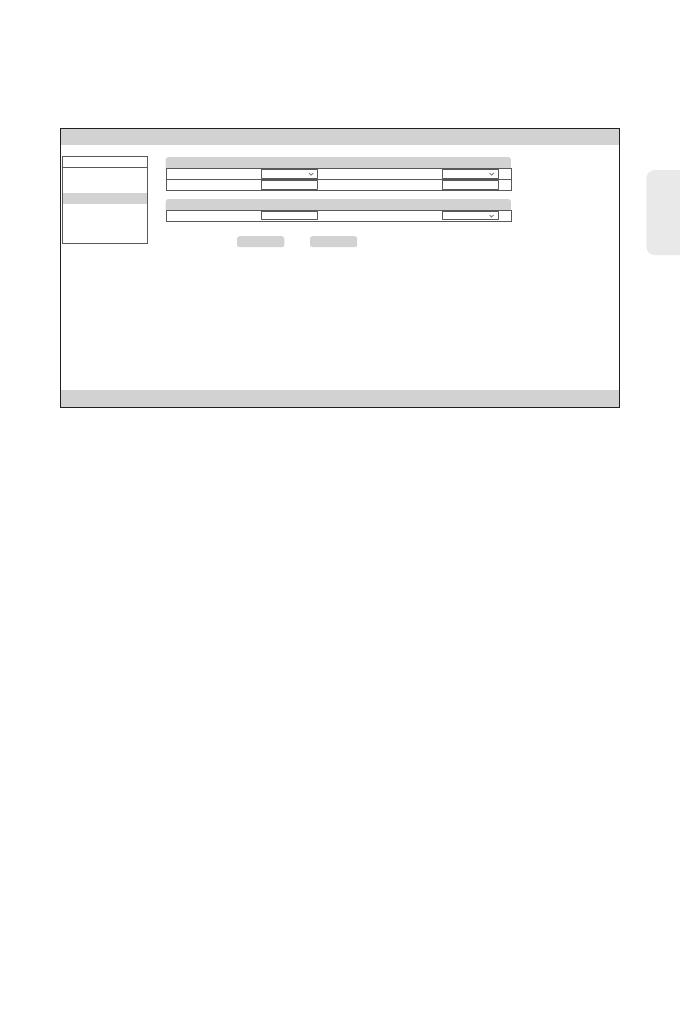
Schritt 4: Suchen Sie "Congure" im MENU auf der linken Seite.
Schritt 5: Klicken Sie auf "Link Conf", dann werden die Parameter automatisch eingestellt.
Link Conf Apply
WebManager Version: 1.00.001
User. superuser Logout
Copyright©2022 FS Corporation.All rights resered.
MENU
Status
Monitor
System
Upgrade
Help
Congure
EDFA Setting
Pre-Amp EDFA SW: On Booster Amp EDFA SW: On
Optical Parameter
TDC -10.00 Fiber Type G652_30km-80km
Pre-Amp EDFA Gain: (dB) 15.00 Pre-Amp EDFA Tilt: (dB) 0.00