Eks Bypass Bedienungsanleitung
- Kategorie
- Komponenten von Sicherheitsgeräten
- Typ
- Bedienungsanleitung

Bedienungsanleitung Manual
MAN_x-light
Version:
3.8.2
/ 20.10.2023
Freigabe:
U.A.
Seite 1 von 5
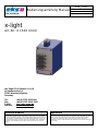
x-light
Art.-Nr.: 0 15X0 XXXX
eks Engel FOS GmbH & Co. KG
Schützenstraße 2-4
57482 Wenden-Hillmicke
Germany
Tel: +49 (0) 2762 9313-600
Fax: +49 (0) 2762 9313-7906
Internet: www.eks-engel.de
Rechtliche Hinweise
Legal Notice
Diese Anleitung enthält wichtige Anmerkungen und Warnungen, deren Nichtbe-
achtung zu ernsthaften Personen- oder Anlageschäden führen kann. Bitte lesen
Sie die Anleitung vor Inbetriebnahme der x-light Geräte aufmerksam durch. Ord-
nungsgemäßer Transport, korrekte Lagerung und Installation sowie sorgfältige
Bedienung und Instandhaltung der x-light sind entscheidend für den sicheren
Betrieb.
This manual contains important notes and warnings. Their ignoration can cause
serious injuries or damages to the system. Please read the manual carefully
before using the equipment x-light. Correct transport, proper storage and
installation as well as careful operation and maintenance of x-light are critical for
safe operation.

Bedienungsanleitung Manual
MAN_x-light
Version:
3.8.2
/ 20.10.2023
Freigabe:
U.A.
Seite 2 von 5
Systembeschreibung
System description
x-light ermöglicht die sichere Kommunikation auch bei Ausfall oder Störung eines
Netzwerkteilnehmers, indem er diesen optisch überbrückt und dadurch den
Datenverkehr permanent gewährleistet. x-light ist hersteller- und protokoll-
unabhängig und integriert sich somit optimal in jedes Netzwerk, egal ob Linien-
oder Ringstruktur. x-light wird aktiviert, wenn eine einstellbare Auslösespannung
unterschritten wird. Zudem kann das System über den Signaleingang flexibel
angesteuert werden, z.B. im Service- oder Fehlerfall. Durch eine einstellbare
Einschaltverzögerung für den Bypass wird das angeschlossene System erst nach
dem abgeschlossenen Bootvorgang zugeschaltet, wenn es in einem sicheren
Zustand ist.
x-light ensures a safe communication even in case of device failure by optically
bypassing the defective node so that a permanent data transmission is
guaranteed. x-light is manufacturer and protocol independent so that it perfectly
integrates into every network, regardless of the structure (ring or line). x-light is
activated once the voltage is lower than the adjusted voltage level. Furthermore,
the system can be controlled flexibly via the trigger input, e.g. in case of service or
failures. The adjustable switch-on delay for the bypass makes sure that the
attached system is in a secure state after booting.
Anschlusshinweise
Hardware Installation
Achtung: Beim Betrieb elektrischer Betriebsmittel und Anlagen stehen
zwangsläufig bestimmte Teile unter gefährlicher Spannung. Arbeiten an
elektrischen Anlagen oder Betriebsmitteln dürfen nur von einer Elektrofachkraft
oder von unterwiesenen Personen unter Anleitung und Aufsicht einer
Elektrofachkraft, den elektrotechnischen Regeln entsprechend, vorgenommen
werden.
Schalten Sie die Systeme und Endgeräte spannungsfrei.
Rasten Sie das Gerät auf eine Tragschiene DIN EN auf, und überprüfen Sie den
sicheren Halt!
Achtung: Benutzen Sie nur passende LWL-Anschlussstecker. Wir weisen
ausdrücklich darauf hin, dass der Anschluss mit falschen Steckverbindern
Schäden an den optischen Anschlüssen hervorrufen kann! Beachten Sie
zudem, dass die Stecker, die eine Verriegelung besitzen, nur in einer
definierten Position montiert werden können.
Achtung: Sehen Sie nicht in den optischen Sender! Das gebündelte und
abhängig von der Wellenlänge sichtbare oder unsichtbare Licht kann zu
Augenschäden führen!
Verbinden Sie die ankommenden Lichtwellenleiter mit dem x-light gemäß der
Beschreibung auf Seite 3.
Benutzen Sie die beigefügten Stopfen um Sender und Empfänger des LWL-
System im nicht eingebauten oder nicht benutzten Zustand vor Verunreini-
gungen oder Staub zu schützen.
Achtung: Knicken Sie das LWL-Kabel nicht zu stark und beachten Sie den
Biegeradius. Andernfalls kann das Kabel beschädigt und/oder die
Kommunikation zwischen den LWL-Wandlern nicht mehr gewährleistet werden.
Schalten Sie die Betriebsspannung für die LWL-Systeme ein. Zur Versorgung der
Systeme wird eine Betriebsspannung von 10-60 VDC benötigt, die an die
Klemmen VDC1 oder VDC2 und GND angelegt wird. VDC1 und VDC2 sind
redundante Versorgungsspannungseingänge mit Verpolungsschutz.
Funktion des DIP-Switch :
Oberer DIP-Switch
SW1 bis SW6 : Schaltschwelle zwischen 10 VDC und 60 VDC
Unterer DIP-Switch
SW1 bis SW4 : Einschaltverzögerung 5 s bis 75 s
SW5 : nicht belegt
SW6 : nicht belegt
Funktion der Status-LEDs:
• VDC1: AN: Versorgungsspannung >10 VDC liegt an VDC1 an.
BLINKT: Versorgungsspannung an VDC1 ist niedriger als die
eingestellte Schwellenspannung (DIP1 bis DIP6).
• VDC2 AN: Versorgungsspannung >10 VDC liegt an VDC2 an.
BLINKT: Versorgungsspannung an VDC2 ist niedriger als die
eingestellte Schwellenspannung (DIP1 bis DIP6).
• Ready AN: Betriebsmodus „NORMAL“.
Fehlerrelais: An den Klemmen K1 bis K3 befindet sich ein potentialfreier
Fehlerrelaiskontakt; K2 ist der gemeinsame Anschluss des Relais. Sobald der
x-light einwandfrei funktioniert zieht das Fehlerrelais an (K1-K2 geschlossen
und K2-K3 geöffnet). Wird die eingestellte Schaltschwelle des x-light
unterschritten oder die Versorgungsspannung unterbrochen, dann wird das
Fehlerrelais geöffnet (K1-K2 geöffnet und K2-K3 geschlossen). Ebenso öffnet
das Fehlerrelais, wenn an keinem der beiden VDC-Eingänge eine Versorgungs-
spannung anliegt.
Funktion der Kontakte K1 - K2: Fehlerrelaiskontakt: Öffnet im Fehlerfall
Funktion der Kontakte K2 - K3: Fehlerrelaiskontakt: Geschlossen im Fehlerfall
Signaleingang / Funktion des Kontakts K4: Signaleingang zur Aktivierung des
Bypass-Modus. Signalspannung 10 VDC bis 60 VDC wird gegen GND geschaltet.
Power off the devices, which will be connected.
Snap the system onto the DIN EN rail and check the correct holding!
Attention: Only use the correct optical connectors for the fiber optic system.
Using incorrect connectors can cause damage to the fiber optic system. Take
care that connectors with a latch can only be mounted in a defined position.
Attention: Don't stare into the optical cable or the transmitter of the fiber optic
system. Visible and non visible light (depending on its wavelength) of the optical
transmitter can cause eye-damages!
Connect the fiber optic system by using the correct fiber optic cable. Note the
wiring diagram on page 3.
Use the plugs to save the unused optical receiver and transmitter against impurity.
Attention: Don't bend the fiber optic cable! Please refer to the manufacturer’s
specification. Otherwise the fiber optic cable can be damaged or the
communication is disturbed.
Power on the devices. Please use a power supply of 10-60 VDC, connected to
the terminals marked with VDC1, VDC 2 and GND. Note, that VDC 1 and
VDC 2 are redundant power inputs with reverse voltage protection.
Function of the DIP-Switch :
Upper DIP-Switch
SW1 to SW6 : Threshold level between 10 VDC and 60 VDC
Lower DIP-Switch
SW1 to SW4 : switch-on delay between 5 s and 75 s
SW5 : without any function
SW6 : without any function
Function of the Status-LEDs:
• VDC1 ON: Power Supply >10 VDC at VDC1.
FLASHING: Power Supply at VDC1 is lower than the
adjusted threshold level (DIP1 to DIP6).
• VDC2 ON: Power Supply >10 VDC at VDC2.
FLASHING: Power Supply at VDC2 is lower than the
adjusted threshold level (DIP1 to DIP6).
• Ready ON: Operation mode “NORMAL”.
Failure Relay: Terminals K1 to K3 are connected to a potential free relay. If the x-
light works without failures the relay gets active and closes K1 to K2 and opens
K2 to K3. The relay will get inactive and K1 to K2 opens and K2 to K3 closes if
the level of the power supply is lower than the adjusted threshold level or the
power supply at VDC1 or VDC2 fails or is disconnected.
Function of K1 – K2: Potential free failure relay contact NC.
Function of K2 – K3: Potential free failure relay contact NO.
Signal Input / Function of K4: Signal Input of 10 VDC up to 60 VDC to enable
the bypass mode.

Bedienungsanleitung Manual
MAN_x-light
Version:
3.8.2
/ 20.10.2023
Freigabe:
U.A.
Seite 3 von 5
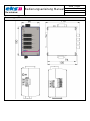
Abmessungen / Dimensions

Bedienungsanleitung Manual
MAN_x-light
Version:
3.8.2
/ 20.10.2023
Freigabe:
U.A.
Seite 4 von 5
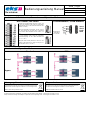
Anschluss und Betriebsarten / Connectors and Operation Modes
DIP-Schalter / DIP-Switch
Schraubklemmen / Screw terminals
Einstellen der Schaltschwelle zwischen 10 VDC und
60 VDC. Das Beispiel rechts zeigt eine eingestellte
Schaltschwelle von 24 VDC (DIP4 und DIP5 auf ON
= 8 VDC + 16 VDC).
Setting the threshold level between 10 VDC and 60
VDC. The example on the right shows a threshold
level of 24 VDC (DIP4 and DIP5 are ON = 8 VDC + 16
VDC).
Signaleingang
Signal Input
10 – 60 VDC
VDC1
VDC2
Earth
GND
K1
K2
K3
K4
Einstellen der Einschaltverzögerung zwischen 5 s und
75 s. Das Beispiel rechts zeigt eine eingestellte
Einschaltverzögerung von 15 s (DIP1 und DIP2 auf
ON = 5 s + 10 s).
Setting the switch-on delay between 5 s and 75 s. The
example on the right shows a switch-on delay of 15 s
(DIP1 and DIP2 are on = 5 s+10 s).
Betriebsmodus / Operation Mode
Standard
BiDi
Normal
Bypass
Entsorgungshinweis
Disposal notes
Die Geräte dürfen nicht über den normalen Hausmüll entsorgt werden,
sondern können bei eks Engel FOS GmbH & Co. KG entsorgt werden.
WEEE-Kennzeichnung: DE 900 53 255
The units must not be disposed with normal household waste but can
be returned to eks Engel FOS GmbH & Co. KG for disposal.
WEEE-identification: DE 900 53 255
Technische Änderungen vorbehalten. Für Irrtümer und Druckfehler keine Haftung. © eks Engel FOS GmbH & Co. KG
Subject to technical changes. No liability is accepted for errors and printing errors. © eks Engel FOS GmbH & Co. KG

Bedienungsanleitung Manual
MAN_x-light
Version:
3.8.2
/ 20.10.2023
Freigabe:
U.A.
Seite 5 von 5
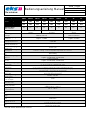
Ausführung XL
Type
50/125-
MM-ST
50/125-
MM-SC
50/125-
MM-LC
62,5/125-
MM-ST
62,5/125-
MM-SC
62,5/125-
MM-LC
9/125-SM-
ST
9/125-SM-
SC
9/125-SM-
LC
Bestell-Nr. x-light-1
Order No.
0 1500
5021
0 1500
5023
0 1500
5024
0 1500
6221
0 1500
6223
0 1500
6224
0 1500
0931
0 1500
0933
0 1500
0934
Bestell-Nr. x-light-2
0 1520
5021
0 1520
5023
0 1520
5024
0 1520
6221
0 1520
6223
0 1520
6224
0 1520
0931
0 1520
0933
0 1520
0934
Order No.
LWL-Anschluss
Fiber-connector
ST
SC
LC
ST
SC
LC
ST
SC
LC
Faser
Fiber
Multi-Mode
50/125µm
Multi-Mode
62,5/125µm
Single-Mode
9/125µm
Wellenlängen
Wavelength
850 nm (±40 nm)
1300 nm (±40 nm)
1310 nm (±40 nm)
1550 nm (±40 nm)
Einfügedämpfung
Insertion Loss
x-light 1: ≤ 1,4dB*
x-light 2: ≤ 1,5dB*
x-light 1: ≤ 1,7dB*
x-light 2: ≤ 1,5dB*
WDL
Wavelength Dependent Loss
≤ 0,35 dB
PDL
Polarization Dependent Loss
≤ 0,05 dB
Lebensdauer Spiegel
Durability switch
10 Millionen Zyklen
10 million cycles
Schaltgeschwindigkeit
Switching speed
15 ms max. / 4 ms typ. / 4 ms im Temperaturbereich von +5 °C bis +70 °C
15 ms max. / 4 ms typ. / 4 ms in a temperature range between +5 °C and +70 °C
Type
Type
Non latching
Rückflussdämpfung
Return Loss
x-light-1: ≥ 55 dB
x-light-2: ≥ 30 dB (MM), ≥ 50 dB (SM)
Übersprechen
Crosstalk
x-light-1: ≥ 55 dB
x-light-2: ≥ 35 dB (MM), ≥ 55 dB (SM)
Einschaltverzögerung
Switch-on delay
5 s, 10 s, 20 s und/oder 40 s schaltbar mit DIP-Schalter
5 s, 10 s, 20 s and/or 40 s switchable by DIP-switch
Schaltschwelle
Threshold level
1 V, 2 V, 4 V, 8 V, 16 V und/oder 32 V im Bereich von 10 V bis 60 V schaltbar mit DIP-Schalter
1 V, 2 V, 4 V, 8 V, 16 V and/or 32 V between 10 V and 60 V switchable by DIP-switch
Anschlussstecker
Connector
4-polig: Stromversorgung / 4-polig: Fehlerrelais und Signaleingang
4-pin: Power supply / 4-pin: Failure relay and signal input
Status - LEDs
Control - LEDs
Stromversorgung (grün) / Ready (grün)
Power supply (green) / Ready (green)
Betriebsspannung
Operating voltage
10 VDC – 60 VDC
Leistungsaufnahme
Power consumption
2,5 W
Fehlerrelais Kontakt
Failure relay contact
25 VDC (1 A) / 60 VDC (0,3 A)
Betriebstemperatur
Operating temperature
x-light-1 (-40 °C - +70 °C )
x-light-2 (-20 °C - +55 °C )
Lagertemperatur
Storage temperature
-40 °C - +85 °C
EMV
EMC
EN61000-6-2 (2005) / EN55032 Kl. B (2016-02)
Gewicht
Weight
500 g
MTBF
MTBF
1.336.702 h
Maße B x H x T
Dimensions W x H x D
B: 61 mm, H: 120 mm, T: 110 mm
W: 61 mm, H: 120 mm, D: 110 mm
Gehäuse
Case
Edelstahl, pulverbeschichtet
Stainless steel, powder-coated
* ohne LWL-Stecker / without fiber optic connectors
-
 1
1
-
 2
2
-
 3
3
-
 4
4
-
 5
5


Eks Bypass Bedienungsanleitung
- Kategorie
- Komponenten von Sicherheitsgeräten
- Typ
- Bedienungsanleitung
in anderen Sprachen
- English: Eks Bypass Owner's manual
Verwandte Papiere
-
Eks DL-232MUX Benutzerhandbuch
-
Eks DL232 Bedienungsanleitung
-
-
-
-
-
-
-
-