ESSENTIELB Fix'TV 32-75'' Bedienungsanleitung
- Kategorie
- Kamine
- Typ
- Bedienungsanleitung

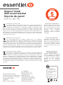
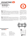
Support mural
Soporte de pared
Wandhalterung
Wall mount bracket
Muurbeugel
FIX'TV 32’’-75’’
Operating instructions
To help you make the most of your purchase
Bedienungsanleitung
Damit Sie an Ihrem Gerät lange Freude haben
Notice d’utilisation
Pour vous aider à bien vivre votre achat
Manual de instrucciones
Para ayudarle a disfrutar de su compra
Handleiding
Om u te helpen zo veel mogelijk te
genieten van uw aankoop

votre produit
2
V.3.0
votre produit
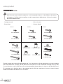
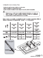
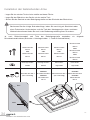
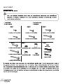
Contenu de la boîte
Afin d’assurer une installation optimale, ce kit comprend diverses vis de différents diamètres
et longueurs. Vérifiez qu’aucune pièce ne soit manquante ou défectueuse. Ne jamais monter
de pièces défectueuses.
!
• 1 plaque murale
• 2 bras fixes
• 1 kit de visserie
• 1 niveau à bulle
6 rondelles M8
6 tirefonds M8x60
4 entretoises M8-4
4 rondelles M4/M5
4 entretoises M8-12
6 chevilles 10x50
1 niveau à bulle
4 rondelles frein M4
4 vis métal M4x12
4 vis métal M4x30
4 rondelles frein M5
4 vis métal M5x12
4 vis métal M5x30
4 rondelles frein M6
4 vis métal M6x12
4 vis métal M6x35
4 rondelles frein M8
4 vis métal M8x16
4 vis métal M8x40
Sachet 1 Sachet 2 Sachet 3
Sachet 4
Sachet 5
Sachet 6
4 entretoises M8-8
4 vis métal M8x45
Quatre sachets de vis de tailles différentes (de 1 à 4) sont fournis afin de sélectionner la visserie requise
pour votre téléviseur. En effet, peu de téléviseurs sont fournis avec le matériel de montage inclus (si des
vis sont fournies avec le téléviseur, elles se trouvent généralement dans les trous au dos du téléviseur).
Si la longueur et le diamètre des vis de montage que le téléviseur requiert est inconnu, testez diverses
tailles en insérant sans forcer les vis à la main.

votre produit
3
V.3.0
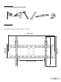
Outils nécessaires (non fournis)
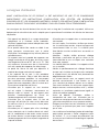
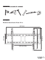
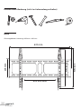
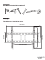
Dimensions
Dimensions totales du support : 633 mm x 430 mm
430 mm
205 mm
633 mm
600 mm Max.
400 mm

votre produit
4
V.3.0
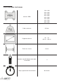
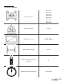
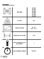
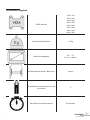
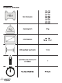
Caractéristiques techniques
Normes VESA
100 x 100
200 x 200
200 x 300
300 x 300
400 x 200
400 x 300
400 x 400
600 x 400
Poids maximum 45 kilos
Diagonale d'écran
32" - 75"
82 cm - 190 cm
Écart mur / écran 16 mm
Nombre conseillé de personne pour
l'installation
2
Temps approximatif d'installation 30 minutes

V.3.0
consignes d'utilisation
5
consignes d’utilisation
AVANT L’INSTALLATION DE CE PRODUIT, IL EST IMPORTANT DE LIRE ET DE COMPRENDRE
PARFAITEMENT LES INSTRUCTIONS D’INSTALLATION AFIN D’ÉVITER LES BLESSURES
CORPORELLES ET LES DOMMAGES MATÉRIELS. GARDEZ CES INSTRUCTIONS D’INSTALLATION
DANS UN ENDROIT FACILEMENT ACCESSIBLE POUR LES CONSULTER ULTÉRIEUREMENT.
Les consignes de sécurité doivent être suivies tout au long de l’installation de ce produit. Utilisez un
équipement de sécurité et des outils adaptés pour la procédure d’installation afin d’éviter les blessures
corporelles.
• Cet appareil est destiné à un usage domestique
uniquement et à l’intérieur d’une habitation.
N’utilisez l’appareil que comme indiqué dans cette
notice d’utilisation.
• Si ce produit devait être vendu ou cédé à une
autre personne, assurez-vous que la notice
d’utilisation l’accompagne et qu’aucune pièce ne
soit défectueuse.
• Ce support mural est capable de supporter une
charge maximale de 45 kg pour les écrans ayant
une diagonale d’écran de 32’’ (82 cm) à 75'’ (190
cm) maximum. Assurez-vous que la structure du
mur soit capable de supporter une telle charge.
• Le poids de l'écran ne doit pas dépasser la
capacité de charge maximale du support.
• Il est impératif de se tenir à une procédure
d’installation correcte. Celle-ci doit être réalisée
par deux personnes qualifiées. Le non-respect
des instructions d’installation peut entraîner de
graves blessures corporelles, liées à la chute ou à
la mauvaise manipulation de l’écran.
• N'installez pas le support sur une structure
qui est sujette à vibrations, mouvements ou
pouvant subir un impact. Le non-respect peut
entraîner l’endommagement de l’écran ou
l’endommagement de la surface du support.
• N'installez pas le support dans un lieu de
passage, afin d’éviter les chocs et les blessures
(au dessus d’un lit, d’une chaise, d’une porte,
dans un couloir…).
• N'installez pas le support près d’un chauffage,
d’une cheminée, de la lumière directe du soleil,
de l’air conditionné ou de toutes autres sources
de chaleur directe. Le non-respect peut entraîner
l’endommagement de l’écran et peut augmenter le
risque d’incendie.
• N'installez pas le support dans un environnement
très humide.
• Un mois après l’installation, vérifiez que toutes
les vis soient bien serrées, et que la plaque soit
correctement fixée au mur. La stabilité peut
être réduite une fois le téléviseur accroché sur
le support.
• Attention : Veuillez vérifier qu'aucun câblage
électrique, canalisation de gaz ou d'eau ne se
trouve derrière le mur sur lequel vous souhaitez
fixer votre support !
• La stabilité peut être réduite si le support est fixé
sur un meuble.
• Vérifiez le positionnement du câblage électrique
lorsque vous installez ou lorsque vous manipulez
le support mural, afin d’éviter tout pincement ou
dégradation des câbles.
• La visserie fournie avec ce support mural est
destinée exclusivement à une fixation sur un
mur constitué de briques pleines ou en béton.
Pour une installation sur tout autre support (bois,
briques creuses, surface en plâtre, acier...), veuillez
contacter un installateur professionnel agréé, et
utiliser du matériel approprié.
• Avant de débuter l’installation, vérifiez la
composition de votre mur. N'installez pas le
support sur une brique ancienne et mal scellée, sur
une surface en plâtre ou sur un panneau en bois.
• Éloignez les enfants lors de l’installation, et veillez
à ce qu’ils ne puissent pas jouer avec l’appareil
par la suite.
• Les matériaux d'emballage (papier d'emballage,
polystyrène) peuvent s'avérer dangereux pour
les enfants : il y a un risque de suffocation. Ne
laissez pas les matériaux d'emballage à la portée
des enfants !

6
V.3.0
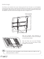
installation de la plaque murale
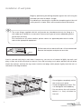
installation de la plaque murale
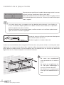
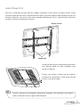
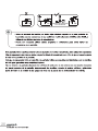
Commencez par positionner le gabarit de perçage contre le mur en
utilisant le niveau à bulle fourni pour le tenir droit.
Utilisez de l'adhésif ou des punaises pour maintenir le gabarit contre
le mur pendant que vous percez les six trous qui seront utilisés pour
fixer le support.
La visserie fournie avec ce support mural est destinée exclusivement à une fixation sur
un mur constitué de briques pleines ou en béton. Veuillez utiliser toutes les vis possibles
(selon le type de mur) pour la fixation.
Pour une installation sur tout autre support, veuillez contacter un installateur professionnel
agréé, et utiliser du matériel approprié.
10mm
60mm
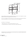
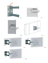
Percez les trous en utilisant une perceuse électrique et
une mèche à béton de 10 mm.
Décollez le gabarit, et mettez-le de coté.
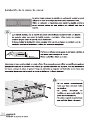
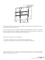
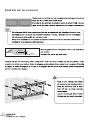
Insérez une cheville à béton dans chaque trou. Si nécessaire, vous pouvez utiliser un marteau pour taper
légèrement sur chaque cheville, afin qu’elles soient au même niveau que le mur. Une fois les chevilles en
place, placez la plaque murale. Fixez les rondelles, puis les tirefonds dans les chevilles qui dépassent
légèrement du mur, comme indiqué sur le schéma ci-dessous.
• Ne serrez pas complètement
avant que toutes les vis soient en
place.
• Ne serrez pas exagérément les
vis. Cela peut endommager le
mur sans aucune nécessité.
• Ne relâchez pas le support mural
avant qu’il soit solidement fixé au
mur.
!

V.3.0
7
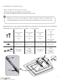
installation des bras xes
installation des bras xes
• Recouvrez une surface stable et plane d’un chiffon doux.
• Placez l'écran de votre appareil sur le chiffon doux.
• Localisez les points de montage filetés situés au dos de l’écran.
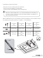
Déterminez la bonne longueur de la vis en insérant délicatement une allumette ou un
cure-dent et marquez la profondeur du point de montage. Reportez vous également à la
notice d’utilisation de votre écran.
!
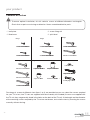
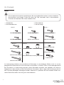
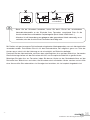
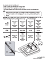
Selon le modèle de votre écran et la profondeur du point de montage, nous vous conseillons d'utiliser
les combinaisons de visserie suivantes (vis + rondelle + 1, 2 ou 3 entretoises) :
M4x30 ou M5x30
M4x12 ou M5x12
M4x12 ou M5x12
M6x12 ou M8x16
M6x35 ou M8x40
M4x12 ou M5x12
Vis métal M4x12
ou
Vis métal M5x12
Vis métal M4x30
ou
Vis métal M5x30
Vis métal M6x12
ou
Vis métal M8x16
Vis métal M6x35
ou
Vis métal M8x40
ou
Vis métal M8x45
M4x30 ou M5x30
M4x12 ou M5x12
M4x12 ou M5x12
M6x12 ou M8x16
M6x35 ou M8x40
M4x12 ou M5x12
Rondelles M4/M5 Rondelles M4/M5 Pas de rondelle Pas de rondelle
Entretoises M8-4
(si nécessaire)
Entretoises M8-4
et/ou
Entretoises M8-8
et/ou
Entretoises M8-12
Entretoises M8-4
(si nécessaire)
Entretoises M8-4
et/ou
Entretoises M8-8
et/ou
Entretoises M8-12
Haut
Bas
Option
Haut
Bas
Haut
Bas
Option
Haut
Bas

8
V.3.0
installation des supports de montage
X
TVTV TV
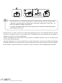
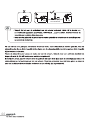
Possibilité de superposer
1 à 3 entretoises
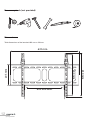
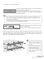
• Avant d'insérer les vis, n’oubliez pas de laisser un espace suffisant au dos de votre écran pour
y disposer la connectique de vos périphériques multimédias (câble péritel, câble HDMI…) en
utilisant les différents modèles d'entretoises.
• L'utilisation de câbles coudés ou articulés est parfois nécessaire pour éviter d'endommager la
connectique de votre écran.
Si votre écran a un dos incurvé ou un point de montage encastré, une entretoise doit être utilisée.
Choisissez l’entretoise qui est la plus proche de la profondeur de l’encastrement afin de garder le
support aussi près de l’écran que possible.
Placez l’entretoise entre le bras fixe et l’écran. Utilisez les rondelles fournies avec les vis M4-M5 pour
assurer une stabilité optimale.
Attachez chaque bras à l’écran en alignant les trous de chaque bras avec les inserts filetés du panneau
arrière de votre écran, en insérant les vis à travers les deux trous et en tournant dans le sens des aiguilles
d’une montre à l’aide d’un tournevis cruciforme, jusqu'à ce qu’elles soient complètement enfoncées.

V.3.0
assemblage nal
9
assemblage nal
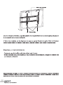
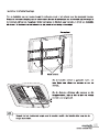
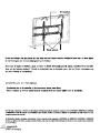
Pour finir l’installation de votre nouveau support, présentez l’écran devant la plaque murale. Placez
l’encoche haute des bras fixés au dos du téléviseur dans la glissière supérieure de la plaque murale. Puis
inclinez le téléviseur vers le bas. Vous devez entendre distinctement un clic, signifiant que le téléviseur
est bien en place et parfaitement maintenu.
Haut
Bas
Si elles sont toujours visibles une fois repliées,
sectionnez les extrémités à l'aide d'une paire de
ciseaux avant de les replier.
Pensez à conserver une longueur suffisante de languette, afin de garder la possibilité
d’ôter le téléviseur de son support ultérieurement.
Lorsque le téléviseur est correctement positionné,
vous pouvez replier les deux languettes pour
former une boucle.
Plaque murale
Languettes

10
V.3.0
entretien et nettoyage
Une fois le téléviseur en place, il est possible de l’ôter de son support, en tirant simplement sur les deux
languettes situées dans le prolongement des bras de fixation.
En tirant sur les languettes, les deux fixations basses s’écartent, libérant la partie inférieure du téléviseur.
Inclinez le bas du téléviseur vers vous, puis soulevez-le pour le retirer complètement.
entretien et nettoyage
• Veuillez vérifier que les vis soient correctement fixées tous les 2 mois.
• Au moindre doute quant à l’installation, contactez votre installateur professionnel.
Toutes les informations, dessins, croquis et images dans ce document relèvent de la propriété exclusive de SOURCING & CREATION. SOURCING
& CREATION se réserve tous les droits relatifs à ses marques, créations et informations. Toute copie ou reproduction, par quelque moyen que ce
soit, sera jugée et considérée comme une contrefaçon.
your product
2
V.3.0
your product
Contents of the box
To ensure optimal installation, this kit contains screws of different diameters and lengths.
Check that no parts are missing or defective. Never assemble defective parts.
!
• 1 wall plate
• 2 xed arms
• 1 screw xings kit
• 1 spirit level
6 rondelles M8
6 tirefonds M8x60
4 entretoises M8-4
4 rondelles M4/M5
4 entretoises M8-12
6 chevilles 10x50
1 niveau à bulle
4 rondelles frein M4
4 vis métal M4x12
4 vis métal M4x30
4 rondelles frein M5
4 vis métal M5x12
4 vis métal M5x30
4 rondelles frein M6
4 vis métal M6x12
4 vis métal M6x35
4 rondelles frein M8
4 vis métal M8x16
4 vis métal M8x40
Sachet 1 Sachet 2 Sachet 3
Sachet 4
Sachet 5
Sachet 6
4 entretoises M8-8
4 vis métal M8x45
Four bags of screws of different sizes (from 1 to 4) are provided so you can select the screws required
for your TV. In fact, few TV sets are supplied with the assembly kit included (if screws are supplied with
the TV set, they are generally found in the holes on the back of the TV set). If the length and the diameter
of the mounting screws required by the TV set are not known, test various sizes by inserting the screws
manually without forcing.
Bag 1
4 metal screws M4x12
4 metal screws M4x30
Bag 4
4 metal screws M8x16
4 metal screws M8x40
4 metal screws M8x45
Bag 5
Bag 5
4 spacers M8-4
6 washers M8
6 lag screws M8x60
6 rawl plugs 10x50
4 spacers M8-12
4 spacers M8-8 4 washers M4/M5
Bag 2
4 metal screws M5x12
4 metal screws M5x30
Bag 3
4 metal screws M6x12
4 metal screws M6x35
Plaque murale
Languettes

V.3.0
11
your product
2
V.3.0
your product
Contents of the box
To ensure optimal installation, this kit contains screws of different diameters and lengths.
Check that no parts are missing or defective. Never assemble defective parts.
!
• 1 wall plate
• 2 xed arms
• 1 screw xings kit
• 1 spirit level
6 rondelles M8
6 tirefonds M8x60
4 entretoises M8-4
4 rondelles M4/M5
4 entretoises M8-12
6 chevilles 10x50
1 niveau à bulle
4 rondelles frein M4
4 vis métal M4x12
4 vis métal M4x30
4 rondelles frein M5
4 vis métal M5x12
4 vis métal M5x30
4 rondelles frein M6
4 vis métal M6x12
4 vis métal M6x35
4 rondelles frein M8
4 vis métal M8x16
4 vis métal M8x40
Sachet 1 Sachet 2 Sachet 3
Sachet 4
Sachet 5
Sachet 6
4 entretoises M8-8
4 vis métal M8x45
Four bags of screws of different sizes (from 1 to 4) are provided so you can select the screws required
for your TV. In fact, few TV sets are supplied with the assembly kit included (if screws are supplied with
the TV set, they are generally found in the holes on the back of the TV set). If the length and the diameter
of the mounting screws required by the TV set are not known, test various sizes by inserting the screws
manually without forcing.
Bag 1
4 metal screws M4x12
4 metal screws M4x30
Bag 4
4 metal screws M8x16
4 metal screws M8x40
4 metal screws M8x45
Bag 5
Bag 5
4 spacers M8-4
6 washers M8
6 lag screws M8x60
6 rawl plugs 10x50
4 spacers M8-12
4 spacers M8-8 4 washers M4/M5
Bag 2
4 metal screws M5x12
4 metal screws M5x30
Bag 3
4 metal screws M6x12
4 metal screws M6x35
your product

12
V.3.0
your product
your product
your product
3
V.3.0
Necessary tools (not provided)
Dimensions
Total dimensions of the bracket: 633 mm x 430 mm
430 mm
205 mm
633 mm
600 mm Max.
400 mm
your product
4
V.3.0
Technical features
VESA standards
100 x 100
200 x 200
200 x 300
300 x 300
400 x 200
400 x 300
400 x 400
600 x 400
Maximum weight 45 kilos
Diagonal of screen
32" - 75"
82 cm - 190 cm
Wall / screen distance 16 mm
Number of people advised for
installation
2
Approximate installation time 30 minutes

V.3.0
13
your product
your product
your product
3
V.3.0
Necessary tools (not provided)
Dimensions
Total dimensions of the bracket: 633 mm x 430 mm
430 mm
205 mm
633 mm
600 mm Max.
400 mm
your product
4
V.3.0
Technical features
VESA standards
100 x 100
200 x 200
200 x 300
300 x 300
400 x 200
400 x 300
400 x 400
600 x 400
Maximum weight 45 kilos
Diagonal of screen
32" - 75"
82 cm - 190 cm
Wall / screen distance 16 mm
Number of people advised for
installation
2
Approximate installation time 30 minutes

14
V.3.0
Operating instructions
your product
V.3.0
Operating instructions
5
Operating instructions
BEFORE INSTALLING THIS PRODUCT, IT IS IMPORTANT TO READ AND UNDERSTAND THE
INSTALLATION INSTRUCTIONS COMPLETELY IN ORDER TO AVOID PHYSICAL INJURIES AND
MATERIAL DAMAGE. KEEP THESE INSTALLATION INSTRUCTIONS IN A PLACE WHICH IS EASILY
ACCESSIBLE SO YOU CAN CONSULT THEM AT A LATER DATE.
The safety instructions must be followed throughout the installation of this product. User safety
equipment and suitable tools for installation in order to avoid physical injury.
• This appliance is intended for domestic use only
inside a dwelling place. Only use the appliance as
indicated in these operating instructions.
• If the product were to be sold or given to another
person, make sure that the operating instructions
are passed on with it and that no parts are defective.
• This wall mount bracket is able to support a
maximum load of 45 kg for screens with a diagonal
measurement of 32” (82 cm) to 75” (190 cm)
maximum. Ensure that the wall structure can
support such a load.
• The weight of the screen must not exceed the
maximum load capacity of the bracket.
• It is essential that you follow a correct installation
procedure. This must be carried out by two
quali ed people. Non-compliance with the installation
instructions may lead to severe physical injury, linked
to falling or incorrect handling of the screen.
• Do not install the bracket on a structure which is
subject to vibrations, movement or which may be
subject to impacts. Non-compliance may lead to
the screen being damaged or the surface of the
bracket being damaged.
• Do not install the bracket in a place of passage in
order to avoid knocks and injuries (above a bed, a
chair, a door or in a corridor…).
• Do not install the bracket near heating, a replace,
direct sunlight, air-conditioning or other sources of
direct heat.
• Non-compliance may lead to the screen being
damaged and may increase the risk of re.
• Do not install the bracket in a very damp environment.
• One month after installation, check that all the
screws are tight and that the wall plate has been
correctly attached to the wall. Stability may be
reduced once the TV is attached to the bracket.
• Please note: Please check that no electric cables,
gas or water pipes are behind the wall onto which
you wish to x your bracket!
• Stability may be reduced if the bracket is attached
to an item of furniture.
• Check the position of the electric cables when you
install or handle the wall bracket, in order to avoid
any pinching or deterioration of the cables.
• The screw xings supplied with this wall bracket
are intended exclusively for xing to a wall made
up of solid bricks or concrete.
• For installation on any other medium (wood, hollow
bricks, plasterboard surfaces, steel…) please
contact an approved professional installer, and use
the appropriate equipment.
• Before beginning installation, please check the
composition of your wall. Do not install the bracket
on old or badly sealed brickwork, on a plasterboard
surface or wood panelling.
• Keep children away from the installation and
ensure that they cannot play with the appliance
subsequently.
• The packaging material (packaging paper,
polystyrene) can be dangerous for children: there
is a risk of suffocation. Do not leave packaging
material within reach of children!
6
V.3.0
installation of wall plate
installation of wall plate
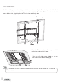
Begin by positioning the drilling template against the wall using the
provided spirit level to keep it straight.
Use adhesive or drawing pins to hold the template against the wall
while you drill six holes which will be used to attach the bracket.
The screw xings supplied with this wall bracket are intended exclusively for xing to a
wall made up of solid bricks or concrete. Please use all types of screws (depending on the
type of wall) for xing.
For installation on any other medium, please contact an approved professional installer,
and use the appropriate equipment
10mm
60mm
Drill the holes with an electric drill and a 10 mm concrete bit.
Remove the template and place to one side.
Insert a concrete rawl plug in each hole. If necessary, you can use a hammer to lightly tap each rawl
plug, so they are at the same level as the wall. Once the rawl plugs are in place, position the wall plate.
Attach the washers and then the lag screws into the rawl plugs which project slightly from the wall, as
indicated in the diagram below.
• Do not tighten completely until all
the screws are in place.
• Do not overtighten the screws. This
can damage the wall needlessly.
• Do not release the wall bracket
before it is firmly attached to
the wall.
!

V.3.0
15
installation of wall plate
your product
V.3.0
Operating instructions
5
Operating instructions
BEFORE INSTALLING THIS PRODUCT, IT IS IMPORTANT TO READ AND UNDERSTAND THE
INSTALLATION INSTRUCTIONS COMPLETELY IN ORDER TO AVOID PHYSICAL INJURIES AND
MATERIAL DAMAGE. KEEP THESE INSTALLATION INSTRUCTIONS IN A PLACE WHICH IS EASILY
ACCESSIBLE SO YOU CAN CONSULT THEM AT A LATER DATE.
The safety instructions must be followed throughout the installation of this product. User safety
equipment and suitable tools for installation in order to avoid physical injury.
• This appliance is intended for domestic use only
inside a dwelling place. Only use the appliance as
indicated in these operating instructions.
• If the product were to be sold or given to another
person, make sure that the operating instructions
are passed on with it and that no parts are defective.
• This wall mount bracket is able to support a
maximum load of 45 kg for screens with a diagonal
measurement of 32” (82 cm) to 75” (190 cm)
maximum. Ensure that the wall structure can
support such a load.
• The weight of the screen must not exceed the
maximum load capacity of the bracket.
• It is essential that you follow a correct installation
procedure. This must be carried out by two
quali ed people. Non-compliance with the installation
instructions may lead to severe physical injury, linked
to falling or incorrect handling of the screen.
• Do not install the bracket on a structure which is
subject to vibrations, movement or which may be
subject to impacts. Non-compliance may lead to
the screen being damaged or the surface of the
bracket being damaged.
• Do not install the bracket in a place of passage in
order to avoid knocks and injuries (above a bed, a
chair, a door or in a corridor…).
• Do not install the bracket near heating, a replace,
direct sunlight, air-conditioning or other sources of
direct heat.
• Non-compliance may lead to the screen being
damaged and may increase the risk of re.
• Do not install the bracket in a very damp environment.
• One month after installation, check that all the
screws are tight and that the wall plate has been
correctly attached to the wall. Stability may be
reduced once the TV is attached to the bracket.
• Please note: Please check that no electric cables,
gas or water pipes are behind the wall onto which
you wish to x your bracket!
• Stability may be reduced if the bracket is attached
to an item of furniture.
• Check the position of the electric cables when you
install or handle the wall bracket, in order to avoid
any pinching or deterioration of the cables.
• The screw xings supplied with this wall bracket
are intended exclusively for xing to a wall made
up of solid bricks or concrete.
• For installation on any other medium (wood, hollow
bricks, plasterboard surfaces, steel…) please
contact an approved professional installer, and use
the appropriate equipment.
• Before beginning installation, please check the
composition of your wall. Do not install the bracket
on old or badly sealed brickwork, on a plasterboard
surface or wood panelling.
• Keep children away from the installation and
ensure that they cannot play with the appliance
subsequently.
• The packaging material (packaging paper,
polystyrene) can be dangerous for children: there
is a risk of suffocation. Do not leave packaging
material within reach of children!
6
V.3.0
installation of wall plate
installation of wall plate
Begin by positioning the drilling template against the wall using the
provided spirit level to keep it straight.
Use adhesive or drawing pins to hold the template against the wall
while you drill six holes which will be used to attach the bracket.
The screw xings supplied with this wall bracket are intended exclusively for xing to a
wall made up of solid bricks or concrete. Please use all types of screws (depending on the
type of wall) for xing.
For installation on any other medium, please contact an approved professional installer,
and use the appropriate equipment
10mm
60mm
Drill the holes with an electric drill and a 10 mm concrete bit.
Remove the template and place to one side.
Insert a concrete rawl plug in each hole. If necessary, you can use a hammer to lightly tap each rawl
plug, so they are at the same level as the wall. Once the rawl plugs are in place, position the wall plate.
Attach the washers and then the lag screws into the rawl plugs which project slightly from the wall, as
indicated in the diagram below.
• Do not tighten completely until all
the screws are in place.
• Do not overtighten the screws. This
can damage the wall needlessly.
• Do not release the wall bracket
before it is firmly attached to
the wall.
!

16
V.3.0
installation of xed arms
V.3.0
installation of wall plate
7
installation of xed arms
installation of xed arms
• Cover a stable, at surface with a soft cloth.
• Place the screen of your appliance on the soft cloth.
• Locate the threaded mount points on the back of the screen.
Determine the correct screw length by carefully inserting a match or toothpick and
marking the depth of the mount point. Refer also to the operating instructions for your screen.
!
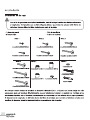
Depending on your screen model and the depth of the mount point, we advise you to use the following
combinations of screw xings (screws + washers + 1, 2 or 3 spacers):
M4x30 ou M5x30
M4x12 ou M5x12
M4x12 ou M5x12
M6x12 ou M8x16
M6x35 ou M8x40
M4x12 ou M5x12
M4 x 12 metal
screws
or
M5 x 12 metal
screws
M4 x 30 metal
screws
or
M5 x 30 metal
screws
M6 x 12 metal
screws
or
M8 x 16 metal
screws
M6 x 35 metal
screws
or
M8 x 40 metal
screws
or
M8 x 45 metal
screws
M4x30 ou M5x30
M4x12 ou M5x12
M4x12 ou M5x12
M6x12 ou M8x16
M6x35 ou M8x40
M4x12 ou M5x12
M4/M5 washers M4/M5 washers No washers No washers
M8-4 spacers
(if needed)
M8-4 spacers
and/or
M8-8 spacers
and/or
M8-12 spacers
M8-4 spacers
(if needed)
M8-4 spacers
and/or
M8-8 spacers
and/or
M8-12 spacers
Haut
Bas
Option
Haut
Bas
Haut
Bas
Option
Haut
Bas
Top
Top
Bottom
Bottom
8
V.3.0
installation of xed arms
X
TVTV TV
Possibilité de superposer
1 à 3 entretoises
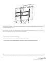
• Before inserting the screws, don’t forget to leave suf cient space behind your screen to
accommodate the connectors of your multimedia devices (scart cable, HDMI cable..) by
using the different models of spacers.
• The use of angled or jointed cables is sometimes necessary to avoid damaging the connections
to your screen.
If your screen has a curved back or a recessed mount point, a spacer must be used.
Choose the spacer which is the closest to the depth of the recess in order to hold the bracket as close
to the screen as possible.
Place the spacer between the xed arm and the screen. Use the washers provided with the M4-M5
screws for optimal stability.
Attach each arm to the screen, aligning the holes in each arm with the threaded inserts on the back panel
of your screen, inserting the screws through the two holes and turning clockwise using a crosshead
screwdriver until they are completely tight.
It is possible to superimpose
1 to 3 spacers

V.3.0
17
installation of xed arms
V.3.0
installation of wall plate
7
installation of xed arms
installation of xed arms
• Cover a stable, at surface with a soft cloth.
• Place the screen of your appliance on the soft cloth.
• Locate the threaded mount points on the back of the screen.
Determine the correct screw length by carefully inserting a match or toothpick and
marking the depth of the mount point. Refer also to the operating instructions for your screen.
!
Depending on your screen model and the depth of the mount point, we advise you to use the following
combinations of screw xings (screws + washers + 1, 2 or 3 spacers):
M4x30 ou M5x30
M4x12 ou M5x12
M4x12 ou M5x12
M6x12 ou M8x16
M6x35 ou M8x40
M4x12 ou M5x12
M4 x 12 metal
screws
or
M5 x 12 metal
screws
M4 x 30 metal
screws
or
M5 x 30 metal
screws
M6 x 12 metal
screws
or
M8 x 16 metal
screws
M6 x 35 metal
screws
or
M8 x 40 metal
screws
or
M8 x 45 metal
screws
M4x30 ou M5x30
M4x12 ou M5x12
M4x12 ou M5x12
M6x12 ou M8x16
M6x35 ou M8x40
M4x12 ou M5x12
M4/M5 washers M4/M5 washers No washers No washers
M8-4 spacers
(if needed)
M8-4 spacers
and/or
M8-8 spacers
and/or
M8-12 spacers
M8-4 spacers
(if needed)
M8-4 spacers
and/or
M8-8 spacers
and/or
M8-12 spacers
Haut
Bas
Option
Haut
Bas
Haut
Bas
Option
Haut
Bas
Top
Top
Bottom
Bottom
8
V.3.0
installation of xed arms
X
TVTV TV
Possibilité de superposer
1 à 3 entretoises
• Before inserting the screws, don’t forget to leave suf cient space behind your screen to
accommodate the connectors of your multimedia devices (scart cable, HDMI cable..) by
using the different models of spacers.
• The use of angled or jointed cables is sometimes necessary to avoid damaging the connections
to your screen.
If your screen has a curved back or a recessed mount point, a spacer must be used.
Choose the spacer which is the closest to the depth of the recess in order to hold the bracket as close
to the screen as possible.
Place the spacer between the xed arm and the screen. Use the washers provided with the M4-M5
screws for optimal stability.
Attach each arm to the screen, aligning the holes in each arm with the threaded inserts on the back panel
of your screen, inserting the screws through the two holes and turning clockwise using a crosshead
screwdriver until they are completely tight.
It is possible to superimpose
1 to 3 spacers

18
V.3.0
nal assembly
V.3.0
nal assembly
9
nal assembly
To nish installing your new bracket, present the screen to the wall plate. Place the top notch of the xed
arms on the back of the screen in the top runner of the wall plate. Then tilt the TV downwards. You should
hear a distinct click, signifying that the TV is in place and rmly held.
Haut
Bas
If they are still visible when folded up, cut the
ends with scissors before folding up.
Remember to leave a cord of suf cient length to allow you to remove the TV from the
bracket later.
When the TV is correctly positioned, you can fold
up the two cords to form a loop.
Cords
Plaque support
10
V.3.0
maintenance and cleaning
Once the TV is in place, it is possible to remove it from its bracket by simply pulling on the two cords at
the end of the mount arms.
By pulling on the cords, the two lower xings move aside, releasing the lower part of the TV. Tilt the TV
downwards towards you, then lift it to remove it completely.
maintenance and cleaning
• Please check that the screws are correctly xed every 2 months.
• If you have the slightest doubt about the installation, contact your professional installer.
All information, designs, drawings and pictures in this document are the property of SOURCING & CREATION. SOURCING & CREATION reserves
all rights to its brands, designs and information. Any copy and reproduction through any means shall be deemed and considered as counterfeiting.
Cords
Plaque support

V.3.0
19
maintenance and cleaning
V.3.0
nal assembly
9
nal assembly
To nish installing your new bracket, present the screen to the wall plate. Place the top notch of the xed
arms on the back of the screen in the top runner of the wall plate. Then tilt the TV downwards. You should
hear a distinct click, signifying that the TV is in place and rmly held.
Haut
Bas
If they are still visible when folded up, cut the
ends with scissors before folding up.
Remember to leave a cord of suf cient length to allow you to remove the TV from the
bracket later.
When the TV is correctly positioned, you can fold
up the two cords to form a loop.
Cords
Plaque support
10
V.3.0
maintenance and cleaning
Once the TV is in place, it is possible to remove it from its bracket by simply pulling on the two cords at
the end of the mount arms.
By pulling on the cords, the two lower xings move aside, releasing the lower part of the TV. Tilt the TV
downwards towards you, then lift it to remove it completely.
maintenance and cleaning
• Please check that the screws are correctly xed every 2 months.
• If you have the slightest doubt about the installation, contact your professional installer.
All information, designs, drawings and pictures in this document are the property of SOURCING & CREATION. SOURCING & CREATION reserves
all rights to its brands, designs and information. Any copy and reproduction through any means shall be deemed and considered as counterfeiting.
Cords
Plaque support

20
V.3.0
6 rondelles M8
6 tirefonds M8x60
4 entretoises M8-4
4 rondelles M4/M5
4 entretoises M8-12
6 chevilles 10x50
1 niveau à bulle
4 rondelles frein M4
4 vis métal M4x12
4 vis métal M4x30
4 rondelles frein M5
4 vis métal M5x12
4 vis métal M5x30
4 rondelles frein M6
4 vis métal M6x12
4 vis métal M6x35
4 rondelles frein M8
4 vis métal M8x16
4 vis métal M8x40
Sachet 1 Sachet 2 Sachet 3
Sachet 4
Sachet 5
Sachet 6
4 entretoises M8-8
4 vis métal M8x45
430 mm
205 mm
633 mm
600 mm Max.
400 mm
Seite wird geladen ...
Seite wird geladen ...
Seite wird geladen ...
Seite wird geladen ...
Seite wird geladen ...
Seite wird geladen ...
Seite wird geladen ...
Seite wird geladen ...
Seite wird geladen ...
Seite wird geladen ...
Seite wird geladen ...
Seite wird geladen ...
Seite wird geladen ...
Seite wird geladen ...
Seite wird geladen ...
Seite wird geladen ...
Seite wird geladen ...
Seite wird geladen ...
Seite wird geladen ...
Seite wird geladen ...
Seite wird geladen ...
Seite wird geladen ...
Seite wird geladen ...
Seite wird geladen ...
Seite wird geladen ...
Seite wird geladen ...
Seite wird geladen ...
Seite wird geladen ...
Seite wird geladen ...
-
 1
1
-
 2
2
-
 3
3
-
 4
4
-
 5
5
-
 6
6
-
 7
7
-
 8
8
-
 9
9
-
 10
10
-
 11
11
-
 12
12
-
 13
13
-
 14
14
-
 15
15
-
 16
16
-
 17
17
-
 18
18
-
 19
19
-
 20
20
-
 21
21
-
 22
22
-
 23
23
-
 24
24
-
 25
25
-
 26
26
-
 27
27
-
 28
28
-
 29
29
-
 30
30
-
 31
31
-
 32
32
-
 33
33
-
 34
34
-
 35
35
-
 36
36
-
 37
37
-
 38
38
-
 39
39
-
 40
40
-
 41
41
-
 42
42
-
 43
43
-
 44
44
-
 45
45
-
 46
46
-
 47
47
-
 48
48
-
 49
49


ESSENTIELB Fix'TV 32-75'' Bedienungsanleitung
- Kategorie
- Kamine
- Typ
- Bedienungsanleitung
in anderen Sprachen
Verwandte Artikel


Andere Dokumente
-
VISA VE-S60T Bedienungsanleitung
-
 VISA VE-L30-T Bedienungsanleitung
-
iiyama MD-WM6080 Benutzerhandbuch
-
Tripp Lite Full Motion Flat Screen Wall Mount Bedienungsanleitung
-
Dynaudio TV1 Benutzerhandbuch
-
Acme United PLB110S Spezifikation
-
Acme United 7009078 Spezifikation
-
-
-
Media Shop M22225 Benutzerhandbuch
