
Vollelektronischer Durchlauferhitzer DCX
Gebrauchsanleitung für den Anwender
Fully electronically controlled instantaneous water heater DCX
Operating instructions for the user
W pełni elektroniczny przepływowy podgrzewacz wody DCX
Instrukcja obsługi dla użytkownika
11.10
DE
EN
PL
2
2
6

DCX 18..27
1 Sicherheitshinweise For your own safety
Installation, initial operation and maintenance of this
appliance must only be conducted by an authorised pro-
fessional, who will then be responsible for adherence
to applicable standards and installation regulations. We
assume no liability for any damages caused by failure to
observe these instructions.
•Do not use the appliance until it has been correctly installed
and unless it is in perfect working order.
•The appliance is only suitable for domestic use and similar
applications inside closed, frost-free rooms, and must only
be used to heat incoming water from mains supply. It is not
allowed to be used with preheated water.
•The appliance must never be exposed to frost.
•The appliance must be earthed at all times.
•The minimal specific water resistance must not fall below the
value stated on the label.
•The maximum water pressure must not exceed the value on
the label.
•Before commissioning for the first time and each time the
appliance is emptied (e.g. due to work on the plumbing sys-
tem, if there is a risk of freezing or in case of maintenance),
the appliance must be vented correctly in accordance with the
instructions in this manual.
•Do not remove the front cover under any circumstances before
switching off the mains electrical supply to the unit.
•Never make technical modifications, either to the appliance
itself or the electrical leads and water pipes.
•Pay attention to the fact that water temperatures in excess of
approx. 43 °C are perceived as hot, especially by children, and
may cause a feeling of burning. Please note that the fittings
and taps may be very hot when the appliance has been in use
for some time.
•In case of malfunction, disconnect the fuses immediately. In
case of leaks, cut off the cold water supply instantly. Repairs
must only be carried out by the customer service department
or an authorised professional.
•This appliance must not be used by any person (including chil-
dren) with limited physical, sensorial or mental abilities or fail-
ing experience and/or knowledge unless they are supervised
by a person responsible for their safety or received instructions
about how to use the appliance.Children should be supervised
in order to make sure that they do not play with the appliance.
Montage, erste Inbetriebnahme und Wartung dieses
Gerätes dürfen nur durch einen anerkannten Fachhand-
werksbetrieb erfolgen, der dabei für die Beachtung der
bestehenden Normen und Installationsvorschriften voll
verantwortlich ist. Wir übernehmen keine Haftung für
Schäden, die durch Nichtbeachtung dieser Anleitung ent-
stehen!
•Benutzen Sie das Gerät nur, nachdem es korrekt installiert
wurde und wenn es sich in technisch einwandfreiem Zustand
befindet.
•Das Gerät ist nur für den Hausgebrauch und ähnliche Zwecke
innerhalb geschlossener und frostfreier Räume geeignet und
darf nur zum Erwärmen von Trinkwasser verwendet werden. Es
ist nicht zum Betrieb mit vorgewärmten Wasser zugelassen.
•Das Gerät darf niemals Frost ausgesetzt werden.
•Das Gerät muss dauerhaft und zuverlässig geerdet werden.
•Der auf dem Typenschild angegebene minimale spezifische
Wasserwiderstand darf nicht unterschritten werden.
•Der auf dem Typenschild angegebene maximale Wasserdruck
darf zu keinem Zeitpunkt überschritten werden.
•Vor der ersten Inbetriebnahme sowie nach jeder Entleerung
(z.B. durch Arbeiten in der Wasserinstallation oder wegen
Frostgefahr oder Wartung) muss das Gerät gemäß den
Hinweisen in der Anleitung ordnungsgemäß entlüftet werden.
•Öffnen Sie niemals das Gerät, ohne vorher die Stromzufuhr
zum Gerät dauerhaft unterbrochen zu haben.
•Nehmen Sie am Gerät oder an den Elektro- und
Wasserleitungen keine technischen Änderungen vor.
•Beachten Sie, dass Wassertemperaturen über ca. 43 °C beson-
ders
bei Kindern als heiß empfunden werden und ein
Verbrennungsgefühl
hervorrufen können. Bedenken Sie, dass nach
längerer Durchlaufzeit
auch die Armaturen entsprechend heiß
werden.
•Im Störungsfall schalten Sie sofort die Sicherungen
aus. Bei einer Undichtigkeit am Gerät schließen Sie
sofort die Kaltwasserzuleitung. Lassen Sie die Störung
nur vom Werkskundendienst oder einem anerkannten
Fachhandwerksbetrieb beheben.
•Dieses Gerät ist nicht dafür bestimmt durch Personen (ein-
schließlich Kinder) mit eingeschränkten physischen, senso-
rischen oder geistigen Fähigkeiten oder mangels Erfahrung
und/oder mangels Wissen benutzt zu werden, es sei denn sie
werden durch eine für ihre Sicherheit zuständige Person beauf-
sichtigt oder erhielten von ihr Anweisungen wie das Gerät zu
benutzen ist. Kinder sollten beaufsichtigt werden, um sicherzu-
stellen, dass sie nicht mit dem Gerät spielen.
2

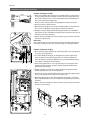
2 Gerätebeschreibung Description of appliance
Der Durchlauferhitzer DCX ist ein mikroprozessor geregelter,
druck fester Durchlauf erhitzer zur dezen tralen Warmwasser-
bereitung an einer oder mehreren Zapfstellen.
Sobald Sie den Warmwasser hahn an der Armatur öffnen,
schaltet sich der Durchlauf erhitzer automatisch ein.
Beim Schließen der Armatur schaltet sich das Gerät auto-
matisch wieder aus.
Die Elektronik passt die Leistungs aufnahme an die jeweilige
Einlauftemperatur und die Durch fluss menge an, um die vorein-
gestellte Auslauftemperatur bis zur Leistungs grenze zu erreichen.
Selbstverständlich ist es auch möglich, die Auslauftemperatur
durch Mischen an der Armatur von Kaltwasser mit heißem
Wasser (55 °C) aus dem Durchlauferhitzer zu bestimmen. Energie-
und wassersparender ist jedoch die Einstellung der jeweiligen
Nutztemperatur am Durchlauferhitzer, ohne kaltes Wasser an der
Armatur zuzumischen.
Bei kühler Zulauftemperatur und hoher Durchflussmenge kann
es wegen Über schreiten der Leistungsgrenze vor kommen, dass
die voreingestellte Aus lauf temperatur nicht erreicht wird. Durch
Reduzieren der Warmwasse r menge an der Armatur kann dann
die Auslauf temperatur erhöht werden.
Der Durchlauferhitzer kann in Kombi nation mit einem externen
Last abwurf relais für elektronische Durch lauf erhitzer oder einer
vorbereiteten Last abwurfbox zum parallelen Anschluss des
Gerätes mit einem elektromechanischen Herd betrieben wer-
den (Details siehe Montageanleitung). Wir empfehlen unsere
Gerätetypen DEX und DSX, falls der Betrieb mit Lastabwurfrelais
notwendig ist. Diese Geräte verfügen über eine besondere
Betriebsart für die Verwendung mit Lastabwurfrelais.
The instantaneous water heater DCX is a micro processor-
con trolled, pressure-resistant water heater for a decentralised
water supply to one or more taps.
As soon as you open the hot water tap,the instantaneous
water heater switches on auto matically. When the tap is
closed, the appliance automatically switches off.
Its electronic control regulates the power consumption automati-
cally depending on the feed temperature and the
flow rate, thus reaching the set outlet temperature up to
the appliance’s power limit.
It is also possible to define the outlet temperature by mixing the
hot water (55 °C) from the instantaneous water heater with cold
water by the tap. However, energy and water will be saved when
selecting the relative temperature to be used on the display of
the instantaneous water heater, without mixing cold water from
the tap.
In case of a low feed temperature and a high flow rate at the
same time, it could happen that the pre-set outlet temperature is
not reached which is due to the fact that the appliance exceeded
its capacity. The outlet temperature can be raised by reducing the
water flow at the tap.
It is possible to use the instantaneous water heater in combina-
tion with an external load shedding relay for electronically con-
trolled instantaneous water heaters or a prepared load shedding
box to operate the appliance along with an electro-mechanic
cooker (refer to installing instructions). We recommend our heat-
ers DEX and DSX as these heaters have a special operation mode
for load shedding relays.
•KunststoffoberflächenundSanitärarmaturennurmiteinem
feuchten Tuch abwischen und keine scheu ern den oder lösungs-
mittelhaltigen Reinigungsmittel verwenden.
•FüreineguteWasserdarbietungsolltenSiedieEntnahme
armaturen (Strahlregler und Handbrausen) regel mäßig
abschrauben und reinigen. Lassen Sie alle drei Jahre die elek-
tro- und wasserseitigen Bauteile durch einen anerkannten
Fachhandwerksbetrieb überprüfen, um die einwandfreie
Funktion und Betriebssicherheit jederzeit zu gewährleisten.
•Plasticsurfacesandfittingsshouldonlybewipedwithadamp
cloth. Never use abrasive cleaners or solvents.
•Foragoodwatersupply,theoutletfittings(jetregulatorsand
shower heads) should be unscrewed and cleaned at regular
intervals. Every three years, the electrical and plumbing com-
ponents should be inspected by an authorised professional in
order to ensure proper functioning and operational safety at all
times.
3 Reinigung und Pflege Cleaning and maintenance
3

DCX 18..27
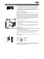
5 Entlüften nach Wartungsarbeiten Venting after maintenance work
Der Durchlauferhitzer DCX muss vor der erst en Inbetriebnahme
entlüftet werden. Nach jeder Entleerung (z.B. nach Arbeiten in
der Wasserinstallation, wegen Frostgefahr oder nach Repara turen
am Gerät) muss das Gerät vor der Wiederinbetriebnahme erneut
entlüftet werden.
1. Trennen Sie den Durchlauferhitzer vom Netz, indem Sie die
Sicherungen aus schalten.
2. Schrauben Sie den Strahlregler an der Entnahmearmatur ab
und öffnen Sie zunächst das Kaltwasserzapfventil, um die
Wasserleitung sauber zu spülen und eine Verschmutzung des
Gerätes oder des Strahlreglers zu vermeiden.
3. Öffnen und schließen Sie danach mehrfach das zugehörige
Warm wasser zapfventil, bis keine Luft mehr aus der Leitung
austritt und der Durch lauferhitzer luftfrei ist.
4. Erst dann dürfen Sie die Stromzufuhr zum Durchlauferhitzer
wieder ein schalten und den Strahlregler wieder ein schrauben.
The instantaneous water heater DCX must be vented before
using it for the first time. Each time the appliance is emptied (e.g.
after work on the plumbing system, if there is a risk of frost or
following repair work), the appliance must be re-vented before it
is used again.
1. Disconnect the instantaneous water heater from the mains by
disactivating the fuses.
2. Unscrew the jet regulator on the outlet fitting and open the
cold water tap valve to rinse out the water pipe and avoid
contaminating the appliance or the jet regulator.
3. Open and close the hot water tap until no more air emerges
from the pipe and all air has been eliminated from the water
heater.
4. Only then should you re-connect the power supply to the
instantaneous water heater and screw the jet regulator back
in.
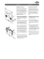
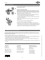
4 Gebrauch How to use
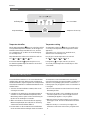
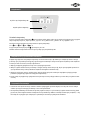
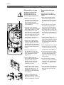
Temperatur einstellen
Mit der Temperaturwahltaste können Sie schnell eine der fünf
voreingestellten Temperaturen auswählen, die für die typischen
Warmwasseranwendungen »Handwäsche« 35 °C, »Dusche«
38 °C, »Badewanne« 42 °C, »Küche« 48 °C und »Reinigung«
55 °C benötigt werden.
Mit jedem Tastendruck stellen Sie die nächsthöhere Stufe ein:
35 °C
38 °C 42 °C 48 °C 55 °C
Bei erneutem Tastendruck
beginnt der Zyklus von vorn.
Die aktuelle eingestellte Temperatur wird durch eine der fünf
farbigen LEDs angezeigt.
Temperature setting
The temperature selection key allows you to quickly select
one of five preset temperatures, that are typical for hot water
applications:
»Hand wash« 35 °C, »Shower« 38 °C, »Bath tub« 42 °C,
»Kitchen« 48 °C und »Cleaning« 55 °C.
Every key press sets the temperature to the next level:
35 °C
38 °C 42 °C 48 °C 55 °C
Pressing the key
once again, starts the cycle all over.
The currently selected temperature is indicated by one of five
coloured LEDs.
Fünf farbige LEDs
Temperaturwahltaste
Five coloured LEDs
Temperature selection key
4

Ihr Durchlauferhitzer DCX wurde sorgfältig hergestellt und vor der Auslieferung
mehrfach überprüft. Tritt ein Problem auf, so liegt es oft nur an einer Kleinigkeit. Schalten
Sie zunächst die Sicherungen aus und wieder ein, um die Elektronik »zurückzusetzen«.
Prüfen Sie dann, ob Sie das Problem mit Hilfe der folgenden Tabelle selbst beheben
können. Sie vermeiden dadurch die Kosten für einen unnötigen Kunden diensteinsatz.
Reparaturen dürfen nur von
anerkannten Fachhandwerks-
betrieben durchgeführt werden.
Wenn sich ein Fehler an Ihrem Gerät
mit dieser Tabelle nicht beheben lässt,
wenden Sie sich bitte an den CLAGE -
Zentral kunden dienst.
Halten Sie die Daten des Geräte-
Typenschildes bereit!
6 Selbsthilfe bei Problemen und Kundendienst
CLAGE GmbH
Zentralkundendienst
Pirolweg 1–7
21337 Lüneburg
Tel.: (04131) 89 01-40
Fax: (04131) 89 01-41
E-Mail: service@clage.de
6 Trouble-shooting and service
Your instantaneous water heater DCX was manufactured conscientiously and checked
several times before delivery. Should malfunctions nevertheless occur, it is usually
something small. First attempt to switch the house fuses off and on again in order to
reset the electronics. Next, try to remedy the problem with reference to the following
table. In doing so, you will avoid the unnecessary expense of customer service assis-
tance.
Repairs must only be carried out by
authorised professionals.
If a fault in your appliance cannot
be rectified with the aid of this
table, please contact the service
organisation of your importer or the
Central Customer Service Department
at CLAGE.
Please have the details of the
typeplate at hand.
CLAGE GmbH
Central Customer Service
Pirolweg 1–7
21337 Lüneburg
Tel.: (+49)4131 89 01-40
Fax: (+49)4131 89 01-41
E-Mail: service@clage.de
Problem Ursache Abhilfe
Wasser bleibt kalt Haussicherung ausgelöst
Sicherung erneuern oder
einschalten
Warmwasserdurchfluss
wird schwächer
Auslaufarmatur
verschmutzt oder verkalkt
Strahlregler, Duschkopf oder
Siebe reinigen
Einlauffiltersieb
verschmutzt oder verkalkt
Filtersieb von Kundendienst
reinigen lassen
Gewählte Temperatur
wird nicht erreicht
Wasserdurchfluss zu groß
Wasserdurchfluss an Armatur
reduzieren
Problem Cause Solution
Water stays cold Master fuse tripped Renew or activate fuse
Flow rate of hot water
too weak
Outlet fitting dirty or
calcified
Clean shower head, jet
regulator or sieves
Fine filter dirty or calcified Clean fine filter
Selected temperature
is not reached
Excessive water flow
(winter?)
Reduce water flow rate at the
outlet
5

4 Sicherheitshinweise Foryourownsafety
DCX 18..27
1 Wskazówki bezpieczeństwa
2 Opis urządzenia
Przepływowy podgrzewacz wody DCX jest sterowanym przy pomocy mikroprocesora, ciśnieniowym przepływowym podgrzewaczem do
zdecentralizowanego dostarczania wody do jednego lub wielu punktów jej poboru.
Podgrzewacz włącza się automatycznie po otwarciu kranu z ciepłą wodą. Po zamknięciu armatury urządzenie automatycz-
nie się wyłącza.
Elektronika dopasowuje pobór mocy w zależności od temperatury wody dolotowej oraz przepływu wody tak, aby uzyskać ustawioną
temperaturę wody wylotowej do granicy posiadanej mocy.
Oczywiście jest możliwe, aby otrzymać odpowiednią temperaturę wody poprzez zmieszanie w armaturze wody gorącej (55°C) z
podgrzewacza z zimną. Bardziej energo- i wodooszczędnym jest ustawienie żądanej temperatury użytkowej na podgrzewaczu, bez
domieszania w armaturze wody zimnej.
Przy niskiej temperaturze wody dolotowej i dużym przepływie wody z powodu przekroczenia granicy mocy urządzenia może dojść do
sytuacji, że nastawiona temperatura wody wylotowej nie zostanie osiągnięta. Poprzez zredukowanie ilości ciepłej wody w armaturze
temperatura wody wylotowej może się podwyższyć.
Podgrzewacz przepływowy może pracować na jednym przyłączu prądu z kuchenką elektryczną za pomocą zewnętrznego przekaźnika
przeciążeniowego dla podgrzewaczy elektronicznych bądź w oparciu o przygotowany przekaźnik priorytetu (detale - patrz instrukcja
montażu). Jeśli konieczne jest użycie przekaźnika przeciążeniowego, zalecamy nasze modele DEX i DSX. Urządzenia te przystosowane
są do współpracy z przekaźnikiem priorytetu.
Montaż, pierwszy rozruch oraz konserwacja podgrzewacza mogą być wykonywane tylko przez autoryzowany zakład usłu-
gowy, który jest w pełni odpowiedzialny za przestrzeganie istniejących norm i przepisów obowiązujących przy instalacji.
Producent nie przejmuje żadnej odpowiedzialności za szkody wynikłe z niezastosowania się do tej instrukcji.
• Korzystać z urządzenia tylko wtedy, gdy zostało poprawnie zainstalowane i gdy jego stan techniczny jest bez zarzutu.
• Urządzenie przeznaczone jest tylko do użytku domowego lub do podobnych celów w obrębie zamkniętych, zabezpieczonych przed
mrozem pomieszczeń. Można je stosować tylko do podgrzewania wody pitnej.
• Urządzenie nie może być poddane działaniu temperatur poniżej 0ºC.
• Urządzenie musi być zawsze na stałe właściwie uziemnione.
• Oporność właściwa wody nie może być niższa niż minimalna wartość podana na tabliczce znamionowej.
• Ciśnienie wody nie może być wyższe niż maksymalna wartość podana na tabliczce znamionowej.
• Przed pierwszym uruchomieniem a także po każdym opróżnieniu z wody (z powodu np. prac przy instalacji wodociągowej, zagroże-
nia poprzez zamarznięcie lub z powodu konserwacji), urządzenie musi być odpowietrzone zgodnie ze wskazówkami zamieszczonymi
na stronie III.
• Nigdy nie zdejmować obudowy podgrzewacza bez uprzedniego trwałego odłączenia zasilania.
• Nie dopuszcza się dokonywania jakichkolwiek zmian technicznych w podgrzewaczu oraz instalacji wodociągowej i elektrycznej po
zainstalowaniu podgrzewacza
• Należy zwracać uwagę na fakt, że woda o temperaturze powyżej 43 °C , w szczególności u dzieci, może być odczuwana jako gorąca
i może wywoływać wrażenie oparzenia. Należy pamiętać, że po dłuższym okresie przepływu wody także armatura odpowiednio się
nagrzewa.
• Temperatura wody dolotowej nie może być wyższa niż 30 °C.
• W przypadku zakłócenia funkcji urządzenia, należy natychmiast wyłączyć bezpieczniki. W przypadku nieszczelności urządzenia,
natychmiast zamknąć dopływ zimnej wody. Usunięcie zakłócenia należy zlecić tylko serwisowi fabrycznemu lub autoryzowanemu
specjalistycznemu zakładowi.
• Urządzenie to nie może być użytkowane przez osoby (włączając dzieci) o ograniczonych zdolnościach psychicznych, sensorycznych
bądź duchowych a także przez osoby nie posiadające wystarczającej wiedzy i doświadczenia, chyba że będą one w towarzystwie
osoby odpowiedzialnej za ich bezpieczeństwo bądź otrzymają odpowiednie instrukcje dotyczące użytkowania urządzenia. Dzieci
powinny być pod opieką osoby dorosłej aby być pewnym, że nie bawią się urządzeniem.
6

Pięć kolorowych wyświetlaczy LED
Przycisk wyboru temperatury
3 Użytkowanie
Ustawianie temperatury
Za pomocą przycisku wyboru temperatury możecie Państwo szybko wybrać jedną z pięciu ustawionych temperatur, które są typowe
dla poszczególnych czynności. „Mycie rąk“ 35 °C, „Prysznic“ 38 °C, „Wanna“ 42 °C, „Kuchnia“ 48 °C i „Sprzątanie“ 55 °C.
Naciśnięcie kolejnych przycisków powoduje ustawienie wyższej temperatury:
35 °C
38 °C 42 °C 48 °C 55 °C
Przy ponownym naciśnięciu przycisku
cykl zaczyna się na nowo.
Aktualnie ustawiona temperatura zaznaczona jest na jednym z pięciu wyświetlaczy LED.
4 Odpowietrzanie po pracach konserwatorskich
Przepływowy podgrzewacz wody DCX przed pierwszym uruchomieniem musi być odpowietrzony. Po każdym opróżnieniu z wody (z
powodu np. prac przy instalacji wodociągowej, zagrożeniu poprzez zamarznięcie lub z powodu napraw urządzenia), zanim urządzenie
zostanie ponownie uruchomione, musi być odpowietrzone.
1. Odłączyć przepływowy podgrzewacz wody od sieci, wyłączając bezpieczniki.
2. Odkręcić regulator strumienia wody od armatury a następnie otworzyć zawór zimnej wody, aby do czysta przepłukać przewód ruro-
wy doprowadzenia wody i uniknąć zabrudzenia urządzenia lub regulatora strumienia wody.
3. Następnie, wielokrotnie otwierać i zamykać zawór ciepłej wody dopóty, dopóki z instalacji nie wydobywać się będą pęcherzyki
powietrza a przepływowy podgrzewacz wody będzie odpowietrzony.
4. Dopiero wtedy do przepływowego podgrzewacza wody można ponownie podłączyć zasilanie i ponownie wkręcić regulator strumie-
nia wody.
• Powierzchnie z tworzywa sztucznego i armatura sanitarna wymagają tylko przetarcia wilgotną ściereczką. Nie stosować żadnych
środków czyszczących zawierających substancje ścierne lub rozpuszczalniki.
• Dla uzyskania prawidłowego dostarczania wody należy regularnie odkręcać i czyścić armaturę (regulator strumienia wody i główki
prysznicowe). Celem zagwarantowania w każdym momencie prawidłowego działania oraz bezpieczeństwa pracy urządzenia, co trzy
lata należy zlecać przegląd części elektrycznych i hydraulicznych uznanemu specjalistycznemu zakładowi.
5 Czyszczenie i konserwacja
7

8
DCX 18..27
Przepływowy podgrzewacz wody DCX został starannie wyprodukowany i wielokrotnie
spraw-dzony przed wysyłką. Jeżeli pojawia się problem, to najczęściej jego przyczyną
jest drobnostka. Najpierw należy wyłączyć i ponownie włączyć bezpieczniki, aby „zrese-
tować” elektronikę. Następnie sprawdzić, czy uda się samemu usunąć problem przy po-
mocy następującej tabeli. Unika się wtedy kosztów za niepotrzebne wezwanie serwisu.
Naprawy mogą być przeprowadzane
tylko przez uznane specjalistyczne
zakłady instalacyjne.
Jeżeli błędu nie da się usunąć przy
pomocy tej tabeli, proszę zwrócić się
do Centralnego Biura Obsługi Klienta
CLAGE. Proszę trzymać w pogotowiu
dane zawarte w tabliczce znamiono-
wej urządzenia!
6 Samodzielne rozwiązanie problemów i serwis klienta
CLAGE Polska Spółka z o.o.
Centralne Biuro Obsługi Klienta
ul. Wichrowa 4
PL-60-449 Poznań
Tel.: (061) 84 99 408
Fax.: (061) 84 99 409
e-mail: info@clage.pl
Problem Przyczyna Usunięcie
Woda pozostaje zimna Przepalony bezpiecznik
Wymienić lub włączyć
bezpiecznik
Przepływ ciepłej wody
jest coraz słabszy
Armatura wypływu wody jest
zabrudzona lub zanieczysz-
czona złogami kamienia.
Oczyścić regulator strumie-
nia wody, główkę prysznico-
wą lub sito
Sito filtra dopływu wody za-
brudzone lub zanieczyszczone
złogami kamienia
Zlecić czyszczenie sita filtra
przez serwis
Wybrana temperatura
nie jest osiągana.
Zbyt duży przepływ wody
Zredukować przepływ wody
przy pomocy armatury
STDB (zabezpieczenie termiczno-ciśnieniowe): przycisk zabezpieczenia może zostać
aktywowany poprzez ostrożne naciskanie czerwonego sztyftu tylko wówczas, gdy przy-
czyna usterki została rozpoznana i usunięta. Gdy zabezpieczenie ponownie zostanie
wyzwolone, skontaktować się koniecznie z serwisem CLAGE!
CLAGE GmbH
Pirolweg 1 – 5
21337 Lüneburg
Telefon: 04131 · 89 01-0
Telefax: 04131 · 83 200
E-Mail: service@clage.de
Internet: www.clage.de
CLAGE GmbH
P.O. Box 16 80
21306 Lüneburg
Fon +49 (0)4131 · 89 01-38
Fax +49 (0) 4131 · 83 200
E-Mail: service@clage.de
Internet: www.clage.com
CLAGE Polska Spółka z o.o.
Centralne Biuro Obsługi Klienta
ul. Wichrowa 4
PL-60-449 Poznań
Tel.: (061) 84 99 408
Fax.: (061) 84 99 409
e-mail: info@clage.pl
internet: www.clage.pl
Änderungen vorbehalten. These instructions are subject to alteration notice. Zmiany zastrzeżone 9120-34200 11.10 GP- BA 10

Vollelektronischer Durchlauferhitzer DCX
Montageanleitung für den Fachhandwerker
Fully electronically controlled instantaneous water heater DCX
Installing instructions for the professional
W pełni elektroniczny przepływowy podgrzewacz wody DCX
Instrukcja montażu dla fachowców
11.10
DE
EN
PL
2
2
16

DCX 18..27
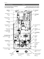
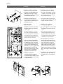
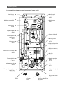
1 Übersichtsdarstellung Overview
2
11 Verbindungsrohr
connecting pipe
82591
12 Elektronikabdeckung
PCB cover
82580
13 Klapphalter
control panel support
82573
14 Anschlussklemme
connecting terminal
82572
15 Einlaufrohr
inlet pipe
82531
19 Kaltwasseranschlussstück
cold water connection
82074
20 Spritzwasserschutztülle
water splash protection
sleeve
in Set 82060
21 Durchführungstülle
grommet
in Set 82180
22 G1/2” Einschraubnippel
screw-in nipples 1/2”
in Set 82110
16 Feinfilter
fine filter
82162
17 Durchflussmengen-
regler 8l/min
flow limiter
89110
18 Rahmen
frame
82571
8DCX Gerätehaube
DCX hood
82508
7Rückflussverhinderer
non-return valve
82246
6Durchflussgeber
flow sensor
82526
3Temperaturfühler Set
thermal sensor set
82512
3Temperaturfühler Set
thermal sensor set
82512
2Auslaufrohr
outlet pipe
82529
1Warmwasseranschlussstück
Hot water connection
82085
5Heizelement mit
Druckschalter
heating element with
pressure switch
82537
10 Geräteunterteil
bottom part
82505
9Wandhalter
wall bracket
82520
4Sicherheits-Temperatur-
Druck-Begrenzer STDB
Safety thermal cut-out STDB
82538
23 Bedienfeld
control panel
82553
23 Bedienfeld
82553
von CKO erhalten 20.6.-MP
Bei Ersatzteilbestellungen stets Gerätetyp
und Serien nummer angeben!
When ordering spare parts, please always
specify the appliance model and serial number.

2 Inhaltsverzeichnis Contents
1. Overview ................................page 2
2. Contents ..................................... 3
3. Environment and recycling ....................... 3
4. Safety instructions ............................. 4
5. Technical specifications ......................... 5
6. Dimensions ................................... 5
7. Installation ................................. 6 – 9
8. Direct connection .............................. 9
9. Electrical connection ........................ 10 – 12
10. Initial operation .............................. 13
Multiple Power System ...................... 14 – 15
11. Maintenance work:
Cleaning and replacing the filter strainer ........... 14
12. Venting after maintenance work .................. 15
Supplementary sheet ”Operating instructions“
1. Safety instructions ............................. 2
2. Description of the appliance ..................... 3
3. Cleaning and maintenance ...................... 3
4. How to use ................................... 4
5. Venting after maintenance work ................... 4
6. Trouble-shooting and service ..................... 5
1. Übersichtsdarstellung ......................Seite 2
2. Inhaltsverzeichnis .............................. 3
3. Umwelt und Recycling .......................... 3
4. Sicherheitshinweise ............................ 4
5. Technische Daten ............................. 5
6. Abmessungen ................................ 5
7. Installation ................................. 6 – 9
8. Aufputzmontage .............................. 9
9. Elektroanschluss (nur durch den Fachmann) ..... 10 – 12
10. Erstinbetriebnahme ........................... 13
Leistungsumschaltung ...................... 14 – 15
11. Wartungsarbeiten:
Reinigung und Wechsel des Filtersiebes ............ 14
12. Entlüften nach Wartungsarbeiten ................. 15
Beilage »Gebrauchsanleitung für den Anwender«
1. Sicherheitshinweise ............................ 2
2. Gerätebeschreibung ............................ 3
3. Reinigung und Pflege ........................... 3
4. Gebrauch .................................... 4
5. Entlüften nach Wartungsarbeiten .................. 4
6. Selbsthilfe bei Problemen und Kundendienst ......... 5
3 Umwelt und Recycling Environment and recycling
Ihr Produkt wurde aus hochwertigen Materialien und Kompo-
nenten entwickelt und hergestellt, die recycelbar und wie-
derverwendbar sind. Dieses Symbol auf Produkten und/
oder begleitenden Dokumenten bedeutet, dass elektrische
und elektronische Produkte am Ende ihrer Lebensdauer vom
Hausmüll getrennt entsorgt werden müssen. Bringen Sie bitte
diese Produkte für die Behandlung, Rohstoffrückgewinnung
und Recycling zu den eingerichteten kommunalen Sammel-
stellen bzw. Werkstoffsammelhöfen, die diese Geräte kostenlos
entgegennehmen. Die ordnungsgemäße Entsorgung dieses
Produktes dient dem Umweltschutz und verhindert mögliche
schädliche Auswirkungen auf Mensch und Umwelt, die sich aus
einer unsachgemäßen Handhabung der Geräte am Ende ihrer
Lebensdauer ergeben könnten.
Genauere Informationen zur nächstgelegenen Sammelstelle
bzw. Recyclinghof erhalten Sie bei Ihrer Gemeindeverwaltung.
Geschäftskunden: wenn Sie elektrische und elektronische Geräte
entsorgen möchten, treten Sie bitte mit Ihrem Händler oder
Lieferanten in Kontakt. Diese halten weitere Informationen für
Sie bereit. Dieses Symbol ist nur in der Europäischen Union gül-
tig.
This symbol on the products and/or accom-
panying documents means that used elec-
trical and electronic products should not be
mixed with general household waste. For
proper treatment, recovery and recycling, please take these pro-
ducts to designated collection points where they will be accepted
on a free of charge basis. Alternatively, in some countries you
may be able to return your products to your local retailer upon
the purchase of an equivalent new product. Disposing of this
product correctly will help to save valuable resources and prevent
any potential negative effects on human health and the envi-
ronment which could otherwise arise from inappropriate waste
handling. Please contact your local authority for further details
of your nearest designated collection point. Penalties may be
applicable for incorrect disposal of this waste, in accordance with
national legislation. If you are a business user and you wish to
discard electrical and electronic equipment, please contact your
dealer or supplier for further information.
This symbol is only valid in the European Union.
3

DCX 18..27
4 Sicherheitshinweise For your own safety
4
Installation, initial operation and maintenance of this
appliance must only be conducted by an authorised pro-
fessional, who will then be responsible for adherence
to applicable standards and installation regulations. We
assume no liability for any damages caused by failure to
observe these instructions.
•Do not use the appliance until it has been correctly installed
and unless it is in perfect working order.
•The appliance is only suitable for domestic use and similar
applications inside closed, frost-free rooms, and must only
be used to heat incoming water from mains supply. It is not
allowed to be used with preheated water.
•The appliance must never be exposed to frost.
•The appliance must be earthed at all times.
•The minimal specific water resistance must not fall below the
value stated on the label.
•The maximum water pressure must not exceed the value on
the label.
•Before commissioning for the first time and each time the
appliance is emptied (e.g. due to work on the plumbing sys-
tem, if there is a risk of freezing or in case of maintenance),
the appliance must be vented correctly in accordance with
the instructions in this manual.
•Do not remove the front cover under any circumstances
before switching off the mains electrical supply to the unit.
•Never make technical modifications, either to the appliance
itself or the electrical leads and water pipes.
•Pay attention to the fact that water temperatures in excess
of approx. 43 °C are perceived as hot, especially by children,
and may cause a feeling of burning. Please note that the fit-
tings and taps may be very hot when the appliance has been
in use for some time.
•In case of malfunction, disconnect the fuses immediately. In
case of leaks, cut off the cold water supply instantly. Repairs
must only be carried out by the customer service department
or an authorised professional.
•This appliance must not be used by any person (including
children) with limited physical, sensorial or mental abilities or
failing experience and/or knowledge unless they are super-
vised by a person responsible for their safety or received
instructions about how to use the appliance.Children should
be supervised in order to make sure that they do not play
with the appliance.
Montage, erste Inbetriebnahme und Wartung dieses Gerätes
dürfen nur durch einen anerkannten Fachhand werksbetrieb
erfolgen, der dabei für die Beachtung der bestehenden
Normen und Installationsvorschriften voll verantwortlich
ist. Wir übernehmen keine Haftung für Schäden, die durch
Nichtbeachtung dieser Anleitung entstehen!
•Benutzen Sie das Gerät nur, nachdem es korrekt installiert
wurde und wenn es sich in technisch einwandfreiem Zustand
befindet.
•Das Gerät ist nur für den Hausgebrauch und ähnliche Zwecke
innerhalb geschlossener und frostfreier Räume geeignet und
darf nur zum Erwärmen von Trinkwasser verwendet werden. Es
ist nicht zum Betrieb mit vorgewärmten Wasser zugelassen.
•Das Gerät darf niemals Frost ausgesetzt werden.
•Das Gerät muss dauerhaft und zuverlässig geerdet werden.
•Der auf dem Typenschild angegebene minimale spezifische
Wasserwiderstand darf nicht unterschritten werden.
•Der auf dem Typenschild angegebene maximale Wasserdruck
darf zu keinem Zeitpunkt überschritten werden.
•Vor der ersten Inbetriebnahme sowie nach jeder Entleerung (z.B.
durch Arbeiten in der Wasserinstallation oder wegen Frostgefahr
oder Wartung) muss das Gerät gemäß den Hinweisen in der
Anleitung ordnungsgemäß entlüftet werden.
•Öffnen Sie niemals das Gerät, ohne vorher die Stromzufuhr zum
Gerät dauerhaft unterbrochen zu haben.
•Nehmen Sie am Gerät oder an den Elektro- und Wasserleitungen
keine technischen Änderungen vor.
•Beachten Sie, dass Wassertemperaturen über ca. 43 °C beson ders
bei Kindern als heiß empfunden werden und ein Verbrennungsgefühl
hervorrufen können. Bedenken Sie, dass nach längerer Durchlaufzeit
auch die Armaturen entsprechend heiß werden.
•Im Störungsfall schalten Sie sofort die Sicherungen
aus. Bei einer Undichtigkeit am Gerät schließen Sie
sofort die Kaltwasserzuleitung. Lassen Sie die Störung
nur vom Werkskundendienst oder einem anerkannten
Fachhandwerksbetrieb beheben.
•Dieses Gerät ist nicht dafür bestimmt durch Personen (ein-
schließlich Kinder) mit eingeschränkten physischen, sensori-
schen oder geistigen Fähigkeiten oder mangels Erfahrung und/
oder mangels Wissen benutzt zu werden, es sei denn sie werden
durch eine für ihre Sicherheit zuständige Person beaufsichtigt
oder erhielten von ihr Anweisungen wie das Gerät zu benutzen
ist. Kinder sollten beaufsichtigt werden, um sicherzustellen, dass
sie nicht mit dem Gerät spielen.

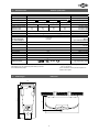
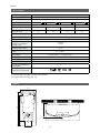
5 Technische Daten Technical specifications
6 Abmessungen Dimensions
231
170
466
56
100
32 1
363
5
231
97
97
231
Typ DCX Model
Bestell-Nr. 3200-34217 Art.no.
Nennleistung / -strom 18 kW..27 kW (26 A..39 A) Rated capacity / rated current
Gewählte/r Leistung/-strom
18 kW (26 A)
21 kW (30 A) 24 kW (35 A) 27 kW (39 A)
Chosen capacity / current
Elektroanschluss 3/PE 380..415 V AC 3/PE 400 V AC Electrical connection
Erforderl. Leiterquerschnitt 4,0 mm
2
4,0 mm
2
6,0
1)
mm
2
6,0 mm
2
Min. required cable size
Warmwasserleistung (l/min)
max. bei ∆t = 28 K
max. bei ∆t = 38 K
9,2
6,8
10,7
7,9
12,3
9,0
13,8
10,2
Hot water (l/min)
max. at ∆t = 28 K
max. at ∆t = 38 K
Nenninhalt 0,4 l Rated volume
Bauart geschlossen, 1 MPa (10 bar) Nennüberdruck / Pressure type 1 MPa (10 bar) Type
Heizsystem Blankdraht IES
®
/ bare wire heating system IES
®
Heating system
Einsatzbereich bei 15 °C:
spez. Wasserwiderstand
spez. elektr. Leitfähigkeit
≥ 1100 Ωcm
≤ 90 mS/m
Required spec. water resistance
@ 15 °C
Spec. electrical conductivity
Einlauftemperatur ≤ 30 °C Inlet temperature
Einschalt- – max. Durchfluss 2,5 – 8,0 l/min
2)
Flow rate to switch on to max.
flow rate
Druckverlust 0,2 bar bei / at 2,5 l/min 1,3 bar bei / at 9,0 l/min
3)
Pressure loss
Einstellbare Temperaturen 35 °C – 38 °C – 42 °C – 48 °C – 55 °C Temperature range
Wasseranschluss G ½“ Water connection
Gewicht (mit Wasserfüllung) 3,65 kg Weight (when filled with water)
Schutzklasse nach VDE I VDE class of protection
Geräuschprüfzeugnis PA-IX 6762/I Noise level test certificate
Schutzart / Sicherheit
IP25
Type of protection / safety
1) Bei Austausch eines 21 kW / 380 V-Gerätes kann der Leiterquerschnitt 4 mm
2
übernommen werden.
2) Durchfluss begrenzt, um optimale Temperaturerhöhung zu erreichen
3) Ohne Durchflussmengenregler
1) When replacing a 21 kW / 380 V appliance the cable size of
4 mm
2
can be adopted.
2) Flow rate limited to achieve optimum temperature rise
3) Without flow regulator

DCX 18..27
Zu beachten sind:
•VDE0100
•EN806-2
•Bestimmungender
örtlichen Energie- und
Wasserversorgungs -
unternehmen
•AngabenaufTypenschild
•TechnischeDaten
Montageort
•GerätnurineinemfrostfreienRaum
installieren. Das Gerät darf niemals
Frost ausgesetzt werden.
•DasGerätistfüreineWandmontage
vorgesehen und muss senkrecht mit
untenliegenden Wasseranschlüssen ins-
talliert werden.
•DasGerätentsprichtderSchutzartIP25
und darf gemäß VDE 0100 Teil 701 im
Schutzbereich 1 installiert werden.
•UmWärmeverlustezuvermeiden,
sollte die Entfernung zwischen
Durchlauferhitzer und Zapfstelle mög-
lichst gering sein.
•FürWartungsarbeitensollteinder
Zuleitung ein Absperrventil installiert
werden. Das Gerät muss für Wartungs-
zwecke zugänglich sein.
•EskönnenWasserleitungenaus
Kupfer oder Stahl ein gesetzt werden.
Kunstoffrohre dürfen nur verwendet
werden, wenn diese DIN 16893 Reihe 2
entsprechen. Die Warmwasserleitungen
müssen wärmegedämmt sein.
•DerspezifischeWiderstanddesWassers
muss bei 15 °C mindestens 1100 Ω cm
betragen. Der spezifische Widerstand
des Wassers kann bei Ihrem Wasser-
versorgungs unternehmen erfragt wer-
den.
The following regulations must be
observed:
•Installationmustcomplywithall
statutory regulations, as well as
those of the local electricity and
water supply companies.
•Thespecificationsontherating
plate
•Technicalspecifications
Installation site
•Appliancemustonlybeinstalledin
frost-free rooms. Never expose appli-
ance to frost.
•TheAppliancemustbewallmounted
and has to be installed with water con-
nectors downward.
•Theappliancecomplieswithprotec-
tion type IP25 and may therefore be
installed in protection zone 1 according
to VDE 0100 part 701.
•Inordertoavoidthermallosses,thedis-
tance between the instantaneous water
heater and the tapping point should be
as small as possible.
•Formaintenancework,ashut-offvalve
should be installed in the supplyline.
The appliance must be accessible for
maintenance work.
•Copperorsteelconnectingpipesmay
be used. Plastic pipes may only be used
if they conform to DIN 16893, Series 2.
The hot water pipes must be thermally
insulated.
•Thespecificresistanceofthewater
must be at least 1100 Ω cm at 15°C.
The specific resistance can be asked for
with your water distribution company.
7 Installation Installation
6
Für dieses Gerät ist aufgrund der
Landesbauordnungen ein allgemei-
nes bauaufsichtliches Prüfzeugnis
zum Nachweis der Verwendbarkeit
hinsichtlich des Geräuschverhaltens
erteilt.
Based on the national constitution
guidelines a general test certificate
concerning the evidence of applica-
bility of noice behaviour is granted.

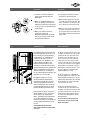
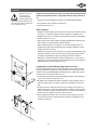
Wandhalter montieren
Wenn Sie den Durchlauferhitzer DCX im
Austausch gegen ein anderes Fabrikat
montieren, müssen in der Regel keine
neuen Löcher für den Wandhalter gebohrt
werden. In diesem Fall brauchen Sie nur
die Einschraubnippel (22) wie unter 2.
beschrieben einzuschrauben und den
Wandhalter zu montieren.
1. Spülen Sie die Wasserzuleitungen
vor der Installation gründlich durch,
um Schmutz aus den Leitungen zu
entfernen.
2. Schrauben Sie die Einschraubnippel mit
einem 12 mm Innensechs kantschlüssel
in die beiden Wand anschlüsse. Der
Überstand der Einschraubnippel muss
nach dem Festziehen 12 mm betragen.
3. Halten Sie die mitgelieferte Montage-
schablone an die Wand und richten
Sie sie so aus, dass die Löcher in der
Schablone über die Anschlüsse passen.
Zeichnen Sie die Bohrlöcher entsprech-
end der Schablone an und bohren Sie
die Löcher mit einem 6 mm -Bohrer.
Setzen Sie die mitgelieferten Dübel ein
und schrauben Sie den Wand halter (9)
an.
4. Fliesenversatz oder Unebenheiten las-
sen sich bis zu 30 mm durch die mitge-
lieferten Distanzhülsen ausgleichen. Die
Distanzhülsen werden zwischen Wand
und Wandhalter montiert.
Installing the wall bracket
If you install the instantaneous water
heater DCX instead of a conventional
instantaneous water heater, there is gen-
erally no need to drill holes for the wall
holder. In this case, you only need
to screw in the double nipples (22) as
described in 2. and to secure the wall
bracket.
1. Thoroughly rinse the water supply
pipes before installation to remove
soiling from the pipes.
2. Using a 12 mm hexagon socket screw
key, screw the screw-in nipples into
the wall connections. After tightening,
the double nipples must protrude by
12 mm.
3. Hold the included mounting template
on the wall and align it so that the
holes in the template fit over the con-
nections. Mark the drill holes according
to the template and drill them using a 6
mm drill. Insert the included dowels and
screw in the wall bracket (9).
4. Offset tiling or uneven surfaces can be
compensated by up to 30 mm with the
aid of the spacers supplied. The spacers
are fitted between the wall and wall
bracket.
22
7 Installation Installation
7

DCX 18..27
7 Installation Installation
Installing connection pieces
1. As shown in the illustration, screw the
cold water connection piece (19) with
the union nut and the 1/2“ seal onto
the cold water connection.
2. Screw the hot water connection piece
(1) with the union nut and the 1/2“ seal
onto the hot water connection.
Installing the appliance
1.To open the appliance hood, take off the
faceplate and unscrew the main hood
screw.
• Whenreplacinganappliance,theelec-
tricalpowersupplycablemaybecon-
nectedintheupperpart.Onlyinsuch
case,followtheinstructionsonpage12
“Electricalconnectionfromabove”.
2. Place the appliance on the heater
bracket (9) so that the threaded rod
of the wall bracket fits in the provided
hole of the appliance. If necessary,
slight corrections are possible by care-
fully bending the threaded rod of the
wall bracket. However, it must be pos-
sible to screw on the water connection
pipes of the appliance without applying
force.
3. Screw the two 3/8“ union nuts of the
appliance‘s water connection pipes,
each with the 3/8“ seal, onto the fit-
tings.
Anschlussstücke installieren
1. Schrauben Sie gemäß Abbildung das
Kaltwasseranschlussstück (19) mit
Überwurfmutter und der 1/2“-Dichtung
an den Kaltwasseranschluss.
2. Schrauben Sie das Warmwasser-
anschlussstück (1) mit Überwurf-
mutter und der 1/2“-Dichtung an den
Warmwasseranschluss.
Gerät montieren
1. Zum Öffnen des Gehäuses die Blende
abnehmen und die zentrale Hauben-
schraube lösen.
•ImAustauschfallkannesvorkom
men,dassdieElektrozuleitungim
oberenGerätebereichvorhandenist.
DerElektroanschlusserfolgtdann
gemässderBeschreibungaufS.12
»Elektroanschlussvonoben«.
2. Setzen Sie das Gerät auf den Wand-
halter (9), so dass die Gewindestange
des Wandhalters in das vorgesehene
Loch des Gerätes passt. Durch vorsich-
tiges Biegen der Gewinde stange des
Wandhalters lassen sich gegebenen falls
kleine Korrekturen vornehmen. Die
Wasseranschluss leitungen des Gerätes
müssen sich jedoch ohne Gewalt-
anwendung anschrauben lassen.
3. Schrauben Sie die beiden
3/8“-Überwurfmuttern der Wasser-
anschlussleitungen des Gerätes jeweils
mit der 3/8“-Dichtung auf die installier-
ten Anschlussstücke.
19
S
1
8

4. Schrauben Sie die Kunststoffrändel-
mutter auf die Gewindestange des
Wandhalters.
5. Öffnen Sie die Wasserzuleitung und
drehen Sie das Absperrventil (19c) im
Kaltwasseranschlussstück (19) langsam
auf (Pos.I). Prüfen Sie alle Verbindungen
auf Dichtigkeit.
6. Öffnen und schließen Sie danach
mehrfach das zugehörige
Warmwasserzapfventil bis keine Luft
mehr aus der Leitung austritt und der
Durchlauferhitzer luftfrei ist.
4. Screw the plastic knurled nut onto the
threaded rod of the wall bracket.
5. Open the water supply line to the unit
and slowly open the shut-off valve (19c)
in the cold water connection piece (19)
(Pos.I). Check all connec tions for leaks.
6. Next, open and close the hot water tap-
ping valve several times until no more
air emerges from the line and all air has
been eliminated from the instantaneous
water heater.
Bei Aufputzmontage sind die beiden 1/2“
Einschraubnippel (22) und die 1/2“ Dich-
tungen mit den 1/2“ Überwurfmuttern
des Warmwasser- (1) und Kaltwasser-
anschlussstückes (19) zu verschrau-
ben. Die beiden 1/2“ Blindkappen der
seitlichen Abgänge des Warm- und
Kaltwasseranschlussstückes sind zu
demontieren und mit dem offenen Ende
der Einschraubnippel zu verschrau ben. Die
Warm- und Kalt wasser anschlussstücke
sind dann mit den 3/8“ Dichtungen an
die 3/8“ Überwurfmutter des Gerätes und
Auslaufrohres zu verschrauben.
Bei Aufputzmontage ist es sinnvoll,
das Gerät mittels der mitgelieferten
Distanzhülsen gemäß nebenstehender
Zeichnung auf Abstand zu montieren.
Dabei ist zu beachten, dass auch die bei-
den Befestigungsbohrungen im unteren
Rohranschlussbereich benutzt werden.
Die Bördelseite der Rohre sind mit 1/2“
Überwurfmuttern und 1/2“ Dichtungen
an die seitlichen 1/2“ Abgänge des
Warm- und Kaltwasseranschluss stückes
zu schrauben. Abschließend sind die
Ausbrüche für die Rohre in der Haube mit
einem stumpfen Gegenstand herauszu-
brechen.
Bei Aufputzmontage beachten:
Sieb in das Kaltwasseranschlussstück
einsetzen!
For direct connection, the two 1/2“ screw-
in nipples (22) and the 1/2“ seals must be
screwed into the 1/2“ union nuts of the
hot-water (1) and cold-water (19) con-
nectors. The two 1/2“ caps of the side
outlets of the hot-water and cold-water
connectors must be removed and screwed
onto the open end of the screw-in nipples.
The hot-water and cold-water connectors
must then be screwed into the 3/8“ union
nut of the appliance and delivery pipe,
together with the 3/8“ seals.
For direct connection, it is advisable to
mount the appliance at a distance as illus-
trated alongside, using the spacer sleeves
supplied. It should therefore be noted that
the two fixing holes near the lower pipe
connections are also used.
The flared end of the pipes must be
screwed into the 1/2“ side outlets of the
hot-water and cold-water connectors with
1/2“ union nuts and 1/2“ seals. The holes
required for the pipes must then be bro-
ken out of the housing with the aid of a
blunt implement.
In case of direct connection please
note: Put the strainer into the cold
water connection!
7 Installation Installation
8 Aufputzmontage Direct connection
9
19 C

DCX 18..27
9 Elektroanschluss (nur durch den Fachmann) Electrical connection (only by a specialist)
Zu beachten sind:
•VDE0100
•EN806-2
•Bestimmungenderörtlichen
Energie- und Wasserversorgungs-
unternehmen
•AngabenTypenschild
•TechnischeDaten
•GerätanSchutzleiteranschließen!
Bauliche Voraussetzungen
•DasGerätmussdauerhaftanfestver-
legte Leitungen angeschlossen werden.
Das Gerät muss an den Schutzleiter
angeschlossen werden.
Kabelquerschnitt maximal 10mm
2
.
•DieElektroleitungenmüssensichin
einem einwandfreien Zustand befinden
und dürfen nach der Montage nicht
mehr berührbar sein.
•Installationsseitigisteineallpolige
Trennvorrichtung mit einer Kontakt-
öffnungsweite von mindestens
3 mm pro Pol vorzusehen (z.B. über
Sicherungen).
•ZurAbsicherungdesGerätesistein
Sicherungselement für Leitungsschutz
mit einem dem Gerätenennstrom an ge-
passten Auslösestrom zu montieren.
Lastabwurfbox / -relais
Beim Anschluss weiterer Drehstromgeräte
empfehlen wir die Verwendung der
CLAGE-Lastabwurfbox (Art.Nr. 82260).
Alternativ kann ein Lastabwurfrelais für
elektronische Durchlauferhitzer (CLAGE
Art.Nr. 82250) an den Außenleiter L
2
angeschlossen werden.
Je nach lokalen Bedingungen ist es nicht
ausgeschlossen, dass es im niedrigen
Leistungsbereich des Durchlauferhitzers
(niedrige Warmwasser temperatur und
geringer Durchfluss) zu einem Flackern der
Lastabwurfrelais kommen kann. Es muss
dann eine höhere Warmwassertemperatur
und ein höherer Durchfluss eingestellt
werden.
Wir empfehlen unsere Gerätetypen
DEX und DSX, falls der Betrieb mit
Lastabwurfrelais notwendig ist. Diese
Geräte verfügen über eine besondere
Betriebsart für die Verwendung mit
Lastabwurfrelais.
Please observe:
•Theinstallationmustcomply
with current IEC and national local
regulations or any particular
regulations, specified by the local
electricity supply company
•Observetheratingplateandtechni-
cal specifications
•Theunitmustbeearthed!
Structural prerequisites
•Theappliancemustbeinstalledviaa
permanent connection. Heater must
be earthed! A maximum cable size of
10 mm
2
must be observed.
•Theelectricwiringshouldnotbe
injured. After mounting, the wiring must
not be direct accessible.
•Anall-poledisconnectingdevice(e.g.
via fuses) with a contact opening width
of at least 3 mm per pole should be
provided at the installation end.
• Toprotecttheappliance,afuseele-
ment must be fitted with a tripping cur-
rent commensurate with the nominal
current of the appliance.
Load shedding box / relay
If further three-phase appliances are
connected, we recommend the use of
CLAGE’s prepared load shedding box (art.
no. 82260). Alternatively, a load shedding
relay (CLAGE art. no. 82250) can be con-
nected to phase conductor L
2
.
Depending on local conditions a jitter
of the load shedding relay might appear
caused by low power consumption of the
instantaneous hot water heater (low tem-
perature set point or low water flow rate).
In this case it has to be set a higher water
temperature or higher water flow rate.
We recommend our heaters DEX and DSX
as these heaters have a special operation
mode for load shedding relays.
10
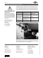
1 Elektronik / Electronic circuitry
2 Heizelement / Heating element
3 Sicherheitsdruckbegrenzer und
Sicherheitstemperatur begrenzer /
Safety pressure switch and Safety
thermal cut-out
4 Klemmleiste / Terminal strip
Schaltplan / Wiring diagram
1
3
4
2

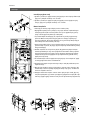
Elektroanschluss von unten
Vergewissern Sie sich vor dem
AnschließendesGerätesan
das elektrische Netz, dass die
Stromversorgung ausgeschaltet ist!
1. Manteln Sie das Anschlusskabel unge-
fähr 6 cm über dem Wandaustritt ab.
Schieben Sie die Spritzwasser schutztülle
(20) mit der kleineren Öffnung voran
über das Anschluss kabel, so dass die
Schutztülle wand bündig abschließt.
Diese verhindert, dass eventuell eindrin-
gendes Wasser mit den Elektroleitungen
in Kontakt kommt. Sie darf nicht
beschädigt sein! Die Schutztülle muss
verwendet werden!
2. Klapphalter (13) nach rechts klappen.
3. Isolieren Sie die Kabel ab und schließen
diese an die Anschlussklemmen gemäß
des auf S. 10 abgebildeten Schaltplanes
an. Das Gerät ist an den Schutzleiter
anzuschließen.
4. Ziehen Sie die Schutztülle so weit über
die Anschlusskabel, dass die Schutz-
tülle einwandfrei in die Aussparung der
Zwischenwand passt. Achten Sie dabei
auf die Ausrichtung der Schutz tülle ent-
sprechend der Abbildung. Klappen Sie
den Klapphalter zurück und rasten Sie
ihn auf der Heizpatrone ein.
5. Setzen Sie das Gehäuse auf das Gerät
und drehen Sie die Befestigungs-
schraube ein. Danach können Sie die
Blende aufrasten.
Hinweis:
Bei Bedarf kann die Anschlussklemme
(14) in den oberen Gerätebereich ver-
legt werden. Bitte folgen Sie hierzu den
Anweisungen im nächsten Abschnitt.
Electrical connection from
below
Check that the power supply is
switched off prior to electrical con-
nection!
1. Strip approximately 6 cm off the con-
necting cable above the wall outlet.
With the smaller opening ahead, slide
the water splash protection sleeve (20)
over the connecting cable so that the
sleeve is flush with the wall. This pre-
vents any leak ing water from coming
into contact with the electrical leads. It
must not become damaged!
The protection sleeve must be used!
2. Open the control panel (13) rightwards.
3. Insulate the cables and plug them
in the connecting terminals according
to the wiring diagram on page 10.
The appliance must be earthed.
4. Pull the protective sleeve over the con-
necting cables until the sleeve
fits perfectly in the recess of the inter-
mediate panel. Adjust the water splash
protection sleeve as illustrated. Reinsert
the front part of the inter mediate panel.
Reinsert the control panel and lock it on
the the heating element.
5. Place the hood on the appliance and
screw in the fastening screw. After that
you can reinsert the faceplate.
Note:
If necessary, the connecting terminal (14)
can be displaced to the upper part of the
appliance. If you want to do so, please fol-
low the instructions in the next chapter.
9 Elektroanschluss (nur durch den Fachmann) Electrical connection (only by a specialist)
11
20 14 13

DCX 18..27
9 Elektroanschluss (nur durch den Fachmann) Electrical connection (only by a specialist)
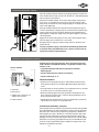
Elektroanschluss von oben
Vergewissern Sie sich vor dem
AnschließendesGerätesan
das elektrische Netz, dass die
Stromversorgung ausgeschaltet ist!
1. Öffnen Sie die im oberen
Geräte bereich vorhandene Soll-
bruchstelle (S) an der Prägung
durch kräftigen Druck mit
einem stumpfen Werkzeug (z.B.
Schraubendreher).
2. Schneiden Sie die Durchfüh-
rungstülle (21) entsprechend dem
Zuleitungsquerschnitt auf. Dabei
soll die Öffnung in der Tülle
etwas kleiner als der Quer schnitt
des Kabels sein, um einen optima-
len Schutz gegen Wasser zu erzie-
len. Passen Sie die Tülle in den
Durchbruch ein. Die Schutztülle
muss verwendet werden!
3. Manteln Sie das Elektrokabel
ungefähr 6 cm über dem Wand-
austritt ab. Nehmen Sie das vor-
bereitete Gerät so in die Hand,
dass Sie mit der anderen Hand das
Kabel in die Gummi tülle führen
können.
4. Setzen Sie das Gerät so auf
den Wandhalter (9), dass die
Gewindestange des Wandhalters
in das vorgesehene Loch des
Gerätes passt.
5. Lösen Sie die Befestigungs-
schraube der Anschlussklemme.
Versetzen Sie die Anschluss-
klemme auf den oberen Fuß.
Befestigen Sie die Anschluss-
klemme dort wieder.
6. Isolieren Sie die Kabel ab und
schließen diese an die Anschluss-
klemmen gemäß des auf S. 10
abgebildeten Schaltplanes an.
Das Gerät ist an den Schutzleiter
anzuschließen.
7. Setzen Sie das Gehäuse auf
das Gerät und drehen Sie die
Befestigungs schraube ein. Danach
können Sie die Blende aufrasten.
Electrical connection from
above
Check that the power supply is
switched off prior to electrical con-
nection!
1. Open the prepared breaking
point (S) in the upper part of
the appliance by pressing with a
blunt implement (e.g. srewdriv-
er).
2. Slit the grommet (21) to match
the cable size. The opening in
the grommet should be slightly
smaller than the cross-section of
the cable in order to ensure opti-
mum protection against water. Fit
the grommet into the opening.
The protection grommet must be
used!
3. Strip the cable roughly 6 cm
above the point where it emerges
from the wall. Hold the prepared
appliance so that you can route
the cable into the grommet with
the other hand.
4. Place the appliance on the heater
bracket (9) so that the threaded
rod of the wall bracket fits in the
provided hole of the appliance.
5. Unscrew the fastening screw of
the connecting terminal. Displace
the connecting terminal to the
upper foot. Affix the connecting
terminal again.
6. Insulate the cables and plug
them in the connecting terminals
according to the wiring diagram
on page 10. The appliance must
be earthed.
7. Place the hood on the appliance
and screw in the fastening screw.
After that you can reinsert the
faceplate.
S
12
Seite wird geladen ...
Seite wird geladen ...
Seite wird geladen ...
Seite wird geladen ...
Seite wird geladen ...
Seite wird geladen ...
Seite wird geladen ...
Seite wird geladen ...
Seite wird geladen ...
Seite wird geladen ...
Seite wird geladen ...
Seite wird geladen ...
-
 1
1
-
 2
2
-
 3
3
-
 4
4
-
 5
5
-
 6
6
-
 7
7
-
 8
8
-
 9
9
-
 10
10
-
 11
11
-
 12
12
-
 13
13
-
 14
14
-
 15
15
-
 16
16
-
 17
17
-
 18
18
-
 19
19
-
 20
20
-
 21
21
-
 22
22
-
 23
23
-
 24
24
-
 25
25
-
 26
26
-
 27
27
-
 28
28
-
 29
29
-
 30
30
-
 31
31
-
 32
32


Verwandte Artikel
-
clage M 3..7 Benutzerhandbuch
-
clage M3..7-O Benutzerhandbuch
-
-
-
clage DLX Next E-convenience Instant Water Heater Benutzerhandbuch
-
-
-
clage FXS 3 Benutzerhandbuch
-
-
clage K5 Benutzerhandbuch
Andere Dokumente
-
Austria Email DEX27 KW Bedienungsanleitung
-
Dimplex DEE 1803 Bedienungsanleitung
-
Kospel KDE3 electronic Benutzerhandbuch
-
Siemens DE06111 Installation And Operating Instructions Manual
-
-
Siemens DE21401 Benutzerhandbuch
-
-
Kerbl 82529 Safari Bedienungsanleitung
-
 ThermoFlow Elex Benutzerhandbuch
-
AEG DDLE24BASIS Benutzerhandbuch
