HPI Racing MTX-249 - MSRS-249 Benutzerhandbuch
- Kategorie
- Ferngesteuertes Spielzeug
- Typ
- Benutzerhandbuch

INSTRUCTIONS

2
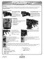
Transmitter
Your Transmitter is an advanced controller designed for the beginner to be easy to use and tune. You will need to
follow the steps below to ensure you prepare the controller correctly for use and understand the adjustment
possibilities available.
Preparing the transmitter
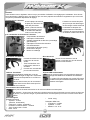
The function switches on the transmitter
Throttle Trigger
Open the battery holding
tray to expose the empty
battery slots.
Insert 4 AA batteries into
the marked spaces. Please
note the correct direction of
the batteries
Incorrect battery insertion could
damage the transmitter
2.4Ghz technology has done
away with the need for long
extendable aerials. The Aerial
on your transmitter is located
internally
1. Steering Trim
2. Power Switch
3. Steering End Point Dial (left/right lock)
4. Steering Reverse Switch
5. Power LED
6. Steering Control
7. Throttle Trigger
8. Bind Button
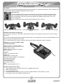
• Pull the trigger to go
forwards and speed up
• Push the trigger forward to
brake
• Push again for reverse
Steering Wheel
Turn the steering wheel to the left or
right to make the vehicle turn left or
right
Reverse Switch
You can reverse the direction travel on the steering by using this switch.
Example: When the car is driving away from you and a left input is made on the Transmitter but the car
steers Right, you can use this switch to reverse the signal to gain the correct steering control.
Dual Rates
The dual rate settings adjust the
maximum degree of movement from the
servo or ESC on that channel.
Clockwise is full movement.
Counter-Clockwise (Zero) is very little
movement.
Power LED’s
The Red LED Light shows if the installed AA
batteries have sufcient charge.
The RED LED will ash if the AA batteries need
replacing.
Specication
Transmitter MTX-249
• System : 2CH
• (Steering, Throttle)
• Frequency : 2.4Ghz - 2.4835Ghz
• Maximum power Output: <100mW
• Radio wave type : FHSS
• Battery : AA x4
• Weight : 227g
Receiver MRX-249
• Frequency : 2.4GHz
• System : 2CH
• Battery : 6.0 - 8.4V

3
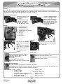
Trim Setup
If the front tyres are not pointing straight forward with the transmitter on, adjust the steering trim. Then if needed, make
ne adjustments with the steering trim whilst driving the vehicle.
Binding the Transmitter and Receiver
You may need to setup your transmitter to ‘bind’ with the receiver if you change to a new receiver or for any reason
lose signal.
Turn on the Transmitter power while holding the “Bind” button on the Transmitter. The LED should start ashing. It will
ash and stay in bind mode for 20 seconds.
Turn on the Reciever/ESC. When the Receiver LED becomes solid the binding process is completed.
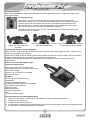
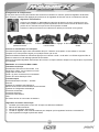
MSRS-249 - 2 in 1 Receiver/ESC 2.4GHz
Technical Information
20A drive FET’s & 15A Reverse FET’s
Case dimensions: 35.1mm*25.3mm*14mm
Silicone Wire 22 Gauge
Weight 7.4g with connectors and switch
BEC Voltage 6.0V
Features
6.0Volt — 8.4Volt Power Input
Waterproof
High Frequency Drive System
Forward, Reverse & Brake Linear Operation
Automatic Setup System
Over Current Protection
Thermal Protection
Low Voltage Protection
LED
20 Turn 370 Brushed Motor Limit
Electronic Speed Control Setup
1. With the speed control switch set to off, plug in a suitable battery pack.
2. Switch the transmitter on
3. Turn on the speed control
4. To indicate the speed control is working correctly its LED will lBlink 3 times and then go solid.
5. Your speed control is fully installed and ready to use.
Steering Trim
When you install a servo or remove the servo horn for any reason, always make sure the servo
is in the neutral position by turing on your car without the servo horn in place. Adjust the Servo
Horn and linkage so they are as close to 90 degrees as possible. Be sure that the “Trim” is in
the central position.
Push forwards to trim to the right and pull backwards to trim to the left.
If the wheels point left, push forwards If wheels point right, pull backwards.
If they point straight no adjustment
required.

4
Sender
Ihr Sender ist ein modernes Steuergerät, dass auch von einem Anfänger leicht zu bedienen und einzustellen ist.
Mit den unten aufgeführten Schritten stellen Sie sicher, dass der Sender für die Verwendung richtig vorbereitet ist und
dass Sie die vorhandenen Einstellmöglichkeiten vollständig verstehen.
Vorbereiten des Senders
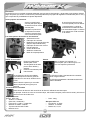
Funktionsschalter am
Sender
Batteriefach öffnen um den
leeren Batterieschacht
freizulegen.
Die 4 AA Batterien in die
markierten Halterungen
einlegen. Dabei auf die
korrekte Richtung achten.
Falsch eingelegte Batterien
können zu Schäden führen.
Mit der 2.4GHz Technik wird
keine lange, ausziehbare
Antenne mehr benötigt. Die
Antenne Ihres Senders ist im
Inneren des Gehäuses
untergebracht.
1. Lenkungstrimmung
2. An/Aus-Schalter
3. Lenkwegbegrenzung
4. Lenkungs-Richtungsschalter
5. Power LEDs
6. Lenkrad
7. Gashebel
8. Bind Button
• Drücken Sie den Gashebel
nach vorne um rückwärts zu
fahren.
• Ziehen Sie den Gashebel
nach hinten um vorwärts zu
fahren und zu beschleuni-
gen
• Für rückwärts erneut
drücken.
Lenkrad
Das Lenkrad nach links oder rechts
drehen, um das Auto nach links bzw.
rechts zu lenken.
Richtungswechsel-Schalter
Mit diesen Schalten können Sie die Lenkrichtung umkehren.
Beispiel: Wenn das Fahrzeug von Ihnen weg fährt, Sie am Sender nach links lenken, das Auto aber nach
rechts fährt, können Sie dies mit diesem Schalter korrigieren.
Endpunkt Einstellknöpfe
Die Dual-Rate Einstellung erlaubt es den
maximalen Weg des Servos oder des
Reglers für diesen Kanal
einzustellen.
Im Uhrzeigersinn für mehr Weg.
Gegen den Uhrzeigersinn (Null) für weniger
Weg.
Power LEDs
Das rote LED Licht zeigt an, ob die eingelegten AA
Batterien ausreichend geladen sind.
Das rote LED Licht blinkt, wenn die AA Batterien
getauscht werden müssen.
Gashebel
Eigenschaften • Gewicht: 227g
Empfänger - MRX-249
• Frequenz: 2.4GHz
• System : 2CH
• Akku : 6.0 - 8.4V
Sender - MTX249
• System: 2 Kanal
• (Lenkung, Gas)
• Frequenz: 2.4Ghz - 2.4835Ghz
• Maximale Leistung Ausgang: <100mW
• Sendemodus: FHSS
• Betriebsspannung: AA x4

5
Lenkungstrimmung
Wenn bei eingeschaltetem Sender die Vorderräder nicht genau geradeaus weisen, korrigieren Sie dies mit der
Lenkungstrimmung.
Verbinden des Senders mit dem Empfänger
Wenn Sie einen neuen Empfänger verwenden oder aus irgendeinem Grund das Signal verlieren, müssen Sie den
Sender und Empfänger neu verbinden.
Halten Sie den “Bind” Knopf am Sender gedrückt und schalten Sie diesen ein. Die LED sollte beginnen zu blinken.
Sobald sie blinkt, bendet sich der Sender für 20 Sekunden im Bind-Modus.
Schalten Sie den Empfänger/Regler ein. Sobald die LED durchgängig leuchtet, ist der Binding-Vorgang
abgeschlossen.
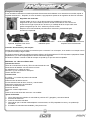
Elektronischer Geschwindigkeitsregler
Technische Informationen
20 A Antrieb FETs & 10 A Rückwärts FETs
Gehäuseabmessungen: 35.1mm*25.3mm*14mm
Silikonkabel 22AWG
Gewicht 7.4g mit Steckern und Schalter
BEC Spannung 6,0 V
Merkmale
6,0Volt — 8,4Volt Speisespannung
Wasserdicht
Hochfrequenz-Antriebssystem
Vorwärts, Rückwärts & Bremse Linear Betrieb
Automatischer Einstellvorgang
Überstromschutz
Überhitzungsschutz
Unterspannungsschutz
LED
13 Turns Motorlimit (370er)
Einstellvorgang des Geschwindigkeitsreglers
1. Stellen Sie den Schalter auf Off-Position und schließen Sie einen geladenen Akkupack an.
2. Schalten Sie den Sender ein.
3. Schalten Sie den Fahrtenregler ein.
4. Um anzuzeigen, dass der Regler korrekt arbeitet, wird seine LED 3 Mal blinken und dann durchgängig leuchten.
5. Ihr Regler ist nun vollständig eingestellt und fahrbereit.
Lenkungstrimmung
Wenn Sie ein neues Servo einbauen oder aus einem anderen Grund das Servohorn
demontieren, achten Sie vor dem Einbau immer darauf das Servo zu zentrieren. Schalten
Sie dazu das Auto bei demontiertem Servohorn ein. Montieren Sie das Servohorn und
das Lenkgestänge so, dass sie möglichst rechtwinklig stehen. Stellen Sie vorher sicher,
dass sich die Trimmung am Sender in der Mittelstellung bendet.
Schieben Sie die Trimmung nach vorne um sie nach rechts zu verstellen und nach hinten
um sie nach links zu verstellen.
Wenn die Räder nach links
zeigen, Trimmung nach vorne
schieben.
Wenn Sie geradeaus zeigen, ist keine
Nachstellung notwendig.
Wenn die Räder nach rechts zeigen,
Trimmung nach hinten schieben.

6
Émetteur
Votre émetteur est un régulateur avancé conçu pour faciliter l’utilisation et le réglage pour le débutant. Vous devrez
suivre les étapes ci-dessous pour vous assurer que vous avez préparé correctement le régulateur et que vous avez
compris les possibilités disponibles de réglage.
Préparation de l’émetteur
Ouvrez la plaque de retenue
des piles pour découvrir les
fentes des piles vides.
Insérez 4 piles AA dans les
espaces marqués à cet ef-
fet. Veuillez faire attention
au sens correct des piles.
L’insertion incorrecte des piles
peut provoquer des dommages.
La technologie 2.4Ghz a éliminé
la nécessité de disposer de
longues antennes extensibles.
L’antenne de votre transmetteur
est située à l’intérieur de celui-ci.
1. Compensateur de direction
2. Interrupteur d’alimentation
3. Cadrans d’extrémité de direction (verrouillage
gauche/droite)
4. Interrupteur marche arrière direction
5. LED d’alimentation
6. Commande de direction (roue)
7. Enclencheur des gaz
8. Bouton de calibrage
• Poussez l’enclencheur vers
l’avant pour la marche
arrière
• Tirez l’enclencheur vers
l’arrière pour avancer et
accélérer
• Poussez une nouvelle fois
pour la marche arrière
Roue directrice
Tournez la roue directrice vers la
gauche ou la droite pour que le véhicule
aille dans cette direction.
Commutateurs de marche arrière
Vous pouvez inverser la direction sur le volant en utilisant cet interrupteur
Par exemple : Vous tournez le volant sur la droite lorsque la voiture s’éloigne et que la voiture se dirige sur
la gauche, vous pouvez corriger ce phénomène avec cet interrupteur pour avoir le contrôle correct de la
voiture.
Cadrans d’extrémité
Les réglages à double taux vous per-
mettent de régler le degré de mouvement
maximum du dispositif servo ou ESC sur
ce canal.
Dans le sens horaire pour le mouvement
entier. Dans le sens anti-horaire pour lim-
iter le mouvement
Voyants LED d’alimentation
Les voyants rouge et vert sont allumés lorsque la
charge des batteries AA installées est sufsante.
Le voyant LED vert clignote et le voyant LED rouge
est éteint lorsque les batteries AA doivent être rem-
placées/ rechargées.
Commande ’accélérateur
Les commandes de fonction de l’émetteur
Caractéristiques
Émetteur MTX-249
• Système : 2 voies
(direction, accélération)
• Fréquence: 2.4Ghz - 2.4835Ghz
• Puissance maximale Sortie: <100mW
• Type d’ondes radio : FHSS
• Piles : AA x4
• Poids : 227g
Récepteur MRX-249
• Fréquence : 2.4GHz
• Système : 2 voies
• Batterie : 6.0 - 8.4V

7
Conguration du compensateur
Si les pneus avant ne sont pas orientés vers l’avant avec l’émetteur en marche, ajustez le régulateur de direction.
Puis au besoin, effectuez des réglages plus précis avec le régulateur de direction tout en conduisant le véhicule.
Associer le transmetteur et le récepteur
Vous devrez peut-être régler votre transmetteur an qu’il ‘s’associe’ au récepteur si vous utilisez un nouveau
récepteur ou si vous perdez le signal, pour quelque raison que ce soit.
Allumez la radiocommande en maintenant appuyer sur le bouton « bind » de la radio. La LED doit clignoter. Elle va
asher et rester en mode calibrage pendant 20 secondes.
Allumez le récepteur/régulateur électronique de la voiture. Lorsque la LED du récepteur ne clignote plus, le processus
est complété.
MSRS-249 - 2 in 1 Receiver/ESC 2.4GHz
Information technique
Entraînement TEC 20 A et TEC Arrière 10 A
Dimensions caisse : 35.1mm*25.3mm*14mm
Jauge à ls en silicone 22
Poids 7.4g avec connecteurs et commutateur
Tension 6V centre électrique à bus
Caractéristiques
Entrée alimentation 6.0 Volts — 8.4Volts
Etanche
Système de conduite haute fréquence
Marche avant, arrière et frein linéaire Fonctionnement
Système de conguration automatique
Protection surintensité
Protection thermique
Protection basse tension
LED
20 Limites de tour du 370 moteur à charbons
Régulateur de vitesse électronique
1. Contrôler que l’interrupteur est sur OFF lorsque vous branchez la batterie
2. Allumez la radiocommande
3. Allumez le régulateur électronique
4. La LED va clignoter 3 fois avant de s’allumer pour indiquer que le régulateur fonctionne correctement.
5. Votre régulateur est réglé et prêt à être utiliser.
Régulateur d’accélérateur
Lorsque vous installez ou désinstallez le palonnier de direction du servo, assurez-vous que
le servo est en position neutre. Ajustez le palonnier de servo et les renvois de direction aussi
proche du 90°. Assurez-vous que le trim est en position centrale.
Poussez en avant pour trimmer sur la droite et en arrière pour trimmer sur la gauche.
Si les roues vont vers la gauche,
poussez en avant.
Si les roues vont vers la droite, tirez en
arrière.
Si elles vont tout droit, aucun réglage
n’est à réaliser.

8
Transmisor
Su transmisor es un regulador avanzado diseñado para que sea de fácil manejo y ajuste para el principiante. Deberá
seguir los pasos que se dan a continuación para asegurarse de que prepara el regulador correctamente para su uso y
que comprende las posibilidades de ajuste disponibles
Cómo preparar el transmisor
Abra el compartimento
para las pilas para dejar a
la vista las ranuras vacías
para las pilas.
Introduzca 4 pilas AA en
los espacios marcados.
Tenga en cuenta la direc-
ción correcta de las pilas.
Si introduce las pilas de forma
incorrecta podría provocar daños.
La tecnología de 2,4 GHz ha
eliminado la necesidad de ante-
nas extensibles largas. La antena
de su transmisor I está colocada
en el interior.
1. Ajuste de dirección
2. Interruptor de corriente
3. Diales de punto nal de dirección
(bloqueo izquierda/derecha)
4. Interruptor de dirección inversa
5. LED de potencia
6. Control de dirección
7. Gatillo de aceleración
8. Botón de emparejamiento
• Empuje el gatillo hacia
delante para invertir
• Tire del gatillo hacia atrás
para ir hacia delante y
acelerar
• Presione nuevamente para
marcha atrás
Volante
Gire el volante a la izquierda y/ o
derecha para que el vehículo gire, a su
vez, a la izquierda y/o derecha.
Conmutadores reversibles
Puede invertir la dirección del recorrido de la dirección utilizando este interruptor.
Por ejemplo: Cuando el coche se encuentra lejos, utilice este interruptor para invertir la señal y así tener el
control correcto de la dirección.
Diales de punto nal
La conguración de dos velocidades
le permite ajustar el máximo grado de
movimiento en ese canal, desde el servo
o ESC.
Hacia la derecha para mayor recorrido.
Hacia la izquierda (Cero) para poco
recorrido
LED de alimentación
El LED Rojo indica si las baterías AA montadas
tienen carga suciente.
El LED Rojo parpadeará si las baterías AA tienen
deben cambiarse.
Los interruptores de función en el transmisor
Gatillo de acelerador
Especicaciones
Emisor MTX-249
• Sistema : 2 Canales
• (Dirección, acelerador)
• Frecuencia : 2,4Ghz - 2,4835 Ghz
• Máxima de salida: <100mW
• Tipo de onda de radio: FHSS
• Batería: AA x4
• Peso : 420g
Receptor MRX-249
• Frecuencia : 2,4GHz
• Sistema : 2 Canales
• Batería: 6,0 - 8,4V

9
Conguración del ajuste
Si los neumáticos delanteros no están apuntando directamente hacia delante con el transmisor encendido, ajuste el
regulador de dirección. Después, en caso necesario, haga pequeños ajustes en el regulador de dirección mientras
conduce el vehículo.
Conexión del transmisor y del receptor
Quizás sea necesario que congure su transmisor para “conectarlo” con el receptor, si se cambia a un receptor nuevo
o si pierde la señal por alguna razón.
Encienda la emisora mientras mantiene apretado el Botón de Emparejamiento. El LED empezará a parpadear. Estará
parpadeando y en modo emparejamiento durante más de 20 segundos.
Encienda el variador. Cuando el LED del receptor se queda jo, el proceso está completado.
MSRS-249- 2 in 1 Receiver/ESC 2.4GHz
Información técnica
TECs de accionamiento de 20 A y TECs de marcha atrás de 10 A
Dimensiones del bastidor: 35.1mm*25.3mm*14mm
22 calibradores con cables de silicio
Peso de 7.4g con conectores e interruptor
Tensión del BEC 6,0 V
Características
6,0 voltios — 8,4 voltios de potencia de entrada
Impermeable
Sistema motor de alta frecuencia
Funcionamiento lineal del freno, avance y marcha atrás
Sistema de conguración de automático
Protección de sobrecorriente
Protección térmica
Protección contra la baja tensión
LED
Límite de 20 revoluciones del 370 motor con ecobillas
Ajuste del Variador
1. Con el interruptor del variador de velocidad en posicion OFF ( apagado ) conecte la bateria
2. Encienda el transmisor
3. Active el control de velocidad
4. Para indicar que el variador está trabajando correctamente, su LED parpadeará 3 veces y se quedará jo
encendido.
5. El variador de velocidad esta instalado y listo para su uso
Regulador del acelerador
Cuando instale un servo o si por alguna razón ha cambiado el horn de servo,
asegúrese de que el servo está en posición neutral al encender el coche sin el horn
de servo en su lugar. Ajuste el horn de servo y el varillaje de tal forma que estén a 90
grados. Asegúrese que el “Trim” está en la posición central.
Desplace el trim hacia delante para trimearlo a la derecha y hacia detrás para
trimearlo a la izquierda.
Si las ruedas apuntan hacia la
izquierda, desplace el trim hacia
delante
Si las ruedas apuntan hacia la derecha,
desplace el trim hacia detrás
Si apuntan derechas no debe
realizarse ajuste.

10
This equipment has been tested and found to comply with the limits for a Class B digital device, pursuant to part 15 of the FCC
Rules. These limits are designed to provide reasonable protection against harmful interference in a residential installation.
This equipment generates, uses, and can radiate radio frequency energy and, if not installed and used in accordance with
the operating instructions, may cause harmful interference to radio communications, however, there is no guarantee that
interference will not occur in a particular installation. If this equipment does cause harmful interference to radio or television
reception, which can be determined by turning the equipment off and in, the user is encouraged to try to correct the
interference by one or more of the following measures:
● Reorient or relocate the receiving antenna.
● Increase the separation between the equipment and the receiver.
● Connect the equipment into an outlet on a circuit different from that to which the receiver is connected.
● Consult the dealer or an experienced technician for help.
This device complies with Part 15 of the FCC Rules and with RSS-210 of lndustry Canada. Operation is subject to the following
two conditions:
1)This device may not cause harmful interference, and….
2)This device must accept any interference received, including interference that may cause undesired operation.
WARNING: Changes or modications made to this equipment not expressly approved by the party responsible for compliance
may void the FCC authorization to operate this equipment.
RF Exposure Statement The MTX-249 transmitter has been tested and meets the FCC RF exposure guidelines when used
with the accessories supplied or designated for this product, and provided at least 20cm separation between the antenna the
user\s body is maintained. Use of other accessories may not ensure compliance with FCC RF exposure guidelines.
FCC COMPLIANCE STATEMENT
The radio equipment type in this product is in compliance with EU Directive 2014/53/EU. The full text of the Declaration of Conformity is
available at www.hpiracing.com/ce
Die Fernsteuerung in diesem Produkt ist in Übereinstimmung mit der EU Direktive 2014/53/EU. Die vollständige Konformitätserklärung ist
erhältlich unter www.hpiracing.com/ce
La radiocommande dans ce produit satisfait aux directives CE 2014/53/EU. La déclaration de conformité complète est disponible sur www.
hpiracing.com/ce
La tipologia di apparecchiature radio in questo prodotto è conforme alla Direttiva 2014/53/EU. dell’Unione Europea. Il testo completo della
Dichiarazione di Conformità è disponibile a sito: www.hpiracing.com/ce
CE COMPLIANCE STATEMENT

11
Notes, Notizen, Notas

12
HPI RACING A/S
Jegindoevej 21
8800 Viborg, Denmark
Tel: +45 89281800
WWW.MAVERICK-RC.COM
-
 1
1
-
 2
2
-
 3
3
-
 4
4
-
 5
5
-
 6
6
-
 7
7
-
 8
8
-
 9
9
-
 10
10
-
 11
11
-
 12
12


HPI Racing MTX-249 - MSRS-249 Benutzerhandbuch
- Kategorie
- Ferngesteuertes Spielzeug
- Typ
- Benutzerhandbuch