Pepperl+Fuchs UB200-12GM-E5-V1 Bedienungsanleitung
- Typ
- Bedienungsanleitung

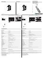
Abmessungen
Elektrischer Anschluss/Kurven/Zusätzliche Informationen Electrical Connection / Curves / Additional Information
Dimensions
Technische Daten
Technical data
UB200-12GM-E5-V1
(Drehmoment)
max. 10 Nm
41
70
LED
17
M12x1
4
6
M12x1
48.4
(Torque)
max. 10 Nm
41
70
LED
17
M12x1
4
6
M12x1
48.4
3 (BU)
1 (BN)
2 (WH)
4 (BK)
U
+ UB
Lerneingang
Schaltausgang
- UB
Adernfarben gemäß EN 60947-5-2.
Normsymbol/Anschluss:
(Version E5, pnp)
1
3
4
2
Abstand X [mm]
Charakteristische Ansprechkurve
Abstand Y [mm]
Kurve 1: ebene Platte 100 mm x 100 mm
Kurve 2: Rundstab, Ø 25 mm
0 50 100 150 200 250 300 350 400
150
100
50
0
-50
-100
-150
1
2
X
Y
Programmierung der Schaltausgänge
1. Fensterbetrieb, Schließerfunktion
A1 < A2:
2. Fensterbetrieb, Öffnerfunktion
A2 < A1:
3. ein Schaltpunkt, Schließerfunktion
A1 -> ∞:
4. ein Schaltpunkt, Öffnerfunktion
A2 -> ∞:
5. A1 -> ∞, A2 -> ∞: Detektion auf Objektanwesenheit
Objekt erkannt: Schaltausgang geschlossen
kein Objekt erkannt: Schaltausgang offen
Objektabstand
A1 A2
A2 A1
A2
A1
Programmable output modes
1. Window mode, normally open mode
A1 < A2:
2. Window mode, normally closed mode
A2 < A1:
3. One switch point, normally open mode
A1 -> ∞:
5. A1 -> ∞, A2 -> ∞: Object presence detection mode
Object detected: Switch output closed
No object detected: Switch output open
4. One switch point, normally closed mode
A2 -> ∞:
object distance
A1 A2
A2 A1
A2
A1
Characteristic response curve
Distance X [mm]
Distance Y [mm]
Curve 1: flat surface 100 mm x 100 mm
Curve 2: round bar, Ø 25 mm
0 50 100 150 200 250 300 350 400
150
100
50
0
-50
-100
-150
1
2
X
Y
3 (BU)
1 (BN)
2 (WH)
4 (BK)
U
+ UB
Teach input
Switch output
- UB
Core colours in accordance with EN 60947-5-2.
Standard symbol/Connections:
(version E5, pnp)
1
3
4
2
Partnummer / Part.
Datum /
182234
07/12/2017 DIN A3 ->
45-1605C
Doc.
1 BN
2 WH
3 BU
4 BK
Wire colors in accordance with EN 60947-5-2
(brown)
(white)
(blue)
(black)
1 BN
2 WH
3 BU
4 BK
Adernfarben gemäß EN 60947-5-2
(braun)
(weiß)
(blau)
(schwarz)
Einstellen der Schaltpunkte
Der Ultraschallsensor verfügt über einen Schaltausgang mit zwei einlernbaren Schaltpunkten. Diese werden durch Anlegen der
Versorgungsspannung -UB bzw. +UB an den Lerneingang eingestellt. Die Versorgungsspannung muss mindestens 1 s am Lerneingang
anliegen. Während des Einlernvorgangs wird mit den LEDs angezeigt, ob der Sensor das Target erkannt hat. Mit -UB wird der Schaltpunkt
A1 und mit +UB der Schaltpunkt A2 eingelernt.
Es sind fünf verschiedene Ausgangsfunktionen einstellbar
1. Fensterbetrieb, Schließerfunktion
2. Fensterbetrieb, Öffnerfunktion
3. ein Schaltpunkt, Schließerfunktion
4. ein Schaltpunkt, Öffnerfunktion
5. Detektion auf Objektanwesenheit
Allgemeine Daten
Erfassungsbereich 15 ... 200 mm
Einstellbereich 20 ... 200 mm
Blindzone 0 ... 15 mm
Normmessplatte 100 mm x 100 mm
Wandlerfrequenz ca. 400 kHz
Ansprechverzug ca. 30 ms
Anzeigen/Bedienelemente
LED gelb Schaltzustandsanzeige
blinkend: Lernfunktion Objekt erkannt
LED rot permanent rot: Störung
rot blinkend: Lernfunktion, Objekt nicht erkannt
Elektrische Daten
Betriebsspannung UB10 ... 30 V DC , Welligkeit 10 %SS
Leerlaufstrom I0≤ 30 mA
Eingang
Eingangstyp 1 Lerneingang
Schaltabstand 1: -UB ... +1 V, Schaltabstand 2: +6 V ... +UB
Eingangsimpedanz: > 4,7 kΩ Lernimpuls: ≥ 1 s
Ausgang
Ausgangstyp 1 Schaltausgang pnp Schließer/Öffner , parametrierbar
Bemessungsbetriebsstrom Ie100 mA , kurzschluss-/überlastfest
Voreinstellung Schaltpunkt A1: 20 mm Schaltpunkt A2: 200 mm
Spannungsfall Ud≤ 3 V
Reproduzierbarkeit ≤ 1 %
Schaltfrequenz f ≤ 13 Hz
Abstandshysterese H 1 % des eingestellten Schaltabstandes
Temperatureinfluss ± 1,5 % vom Endwert
Umgebungsbedingungen
Umgebungstemperatur -25 ... 70 °C (-13 ... 158 °F)
Lagertemperatur -40 ... 85 °C (-40 ... 185 °F)
Mechanische Daten
Anschlussart Gerätestecker M12 x 1 , 4-polig
Schutzart IP67
Material
Gehäuse Messing, vernickelt
Wandler Epoxidharz/Glashohlkugelgemisch; Schaum Polyurethan, Deckel PBT
Masse 25 g
Normen- und Richtlinienkonformität
Normenkonformität
Normen EN 60947-5-2:2007+A1:2012
IEC 60947-5-2:2007 + A1:2012
Zulassungen und Zertifikate
UL-Zulassung cULus Listed, Class 2 Power Source
CCC-Zulassung Produkte, deren max. Betriebsspannung ≤36 V ist, sind nicht zulassungspflichtig und daher nicht
mit einer CCC-Kennzeichnung versehen.
Adjusting the switching points
The ultrasonic sensor features a switch output with two teachable switching points. These are set by applying the supply voltage -UB or +UB
to the TEACH-IN input. The supply voltage must be applied to the TEACH-IN input for at least 1 s. LEDs indicate whether the sensor has
recognised the target during the TEACH-IN procedure. Switching point A1 is taught with -UB, A2 with +UB.
Five different output functions can be set
1. Window mode, normally-open function
2. Window mode, normally-closed function
3. one switching point, normally-open function
4. one switching point, normally-closed function
5. Detection of object presence
General specifications
Sensing range 15 ... 200 mm
Adjustment range 20 ... 200 mm
Dead band 0 ... 15 mm
Standard target plate 100 mm x 100 mm
Transducer frequency approx. 400 kHz
Response delay approx. 30 ms
Indicators/operating means
LED yellow indication of the switching state
flashing: program function object detected
LED red solid red: Error
red, flashing: program function, object not detected
Electrical specifications
Operating voltage UB10 ... 30 V DC , ripple 10 %SS
No-load supply current I0≤ 30 mA
Input
Input type 1 program input
operating distance 1: -UB ... +1 V, operating distance 2: +6 V ... +UB
input impedance: > 4,7 kΩ program pulse: ≥ 1 s
Output
Output type 1 switch output PNP Normally open/closed , programmable
Rated operating current Ie100 mA , short-circuit/overload protected
Default setting Switch point A1: 20 mm Switch point A2: 200 mm
Voltage drop Ud≤ 3 V
Repeat accuracy ≤ 1 %
Switching frequency f ≤ 13 Hz
Range hysteresis H 1 % of the set operating distance
Temperature influence ± 1.5 % of full-scale value
Ambient conditions
Ambient temperature -25 ... 70 °C (-13 ... 158 °F)
Storage temperature -40 ... 85 °C (-40 ... 185 °F)
Mechanical specifications
Connection type Connector M12 x 1 , 4-pin
Degree of protection IP67
Material
Housing brass, nickel-plated
Transducer epoxy resin/hollow glass sphere mixture; foam polyurethane, cover PBT
Mass 25 g
Compliance with standards and directives
Standard conformity
Standards EN 60947-5-2:2007+A1:2012
IEC 60947-5-2:2007 + A1:2012
Approvals and certificates
UL approval cULus Listed, Class 2 Power Source
CCC approval CCC approval / marking not required for products rated ≤36 V
Ultraschallsensor
Ultrasonic sensor
Alle Abmessungen in mm All dimensions im mm

Adressen / Addresses / Adresses / Direcciónes / Indirizzi
Contact Pepperl+Fuchs GmbH · 68301 Mannheim · Germany · Tel. +49 621 776-4411 · Fax +49 621 776-27-4411 · E-mail: fa-info@de.pepperl-fuchs.com
Worldwide Headquarters: Pepperl+Fuchs GmbH · Mannheim · Germany · E-mail: in[email protected]perl-fuchs.com
USA Headquarters: Pepperl+Fuchs Inc. · Twinsburg · USA · E-mail: fa-info@us.pepperl-fuchs.com
Asia Pacific Headquarters: Pepperl+Fuchs Pte Ltd · Singapore · E-mail: fa-inf[email protected]pperl-fuchs.com · Company Registration No. 199003130E
For more contact-adresses refer to the catalogue or internet: http://www.pepperl-fuchs.com
Einlernen Fensterbetrieb, Schließerfunktion
- Target auf nahen Schaltpunkt stellen
- Schaltpunkt A1 mit - UB einlernen
- Target auf fernen Schaltpunkt stellen
- Schaltpunkt A2 mit + UB einlernen
Einlernen Fensterbetrieb, Öffnerfunktion
- Target auf nahen Schaltpunkt stellen
- Schaltpunkt A2 mit + UB einlernen
- Target auf fernen Schaltpunkt stellen
- Schaltpunkt A1 mit - UB einlernen
Einlernen ein Schaltpunkt, Schließerfunktion
- Target auf nahen Schaltpunkt stellen
- Schaltpunkt A2 mit + UB einlernen
- Sensor mit Handfläche abdecken oder alle Objekte aus dem Erfassungsbereich des Sensors entfernen
- Schaltpunkt A1 mit - UB einlernen
Einlernen ein Schaltpunkt, Öffnerfunktion
- Target auf nahen Schaltpunkt stellen
- Schaltpunkt A1 mit - UB einlernen
- Sensor mit Handfläche abdecken oder alle Objekte aus dem Erfassungsbereich des Sensors entfernen
- Schaltpunkt A2 mit + UB einlernen
Einlernen Detektion auf Objektanwesenheit
- Sensor mit Handfläche abdecken oder alle Objekte aus dem Erfassungsbereich des Sensors entfernen
- Schaltpunkt A1 mit - UB einlernen
- Schaltpunkt A2 mit + UB einlernen
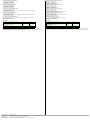
LED-Anzeige
Einbaubedingungen
Bei einem Einbau des Sensors an Orten, an denen die Betriebstemperatur unter 0 °C sinken kann, müssen zur Montage die
Befestigungsflansche BF 12, BF 12-F oder BF 5-30 verwendet werden. Soll der Sensor direkt in einer Durchgangsbohrung montiert
werden, so ist die Befestigung in der Mitte der Sensorhülse vorzunehmen.
Anzeigen in Abhängigkeit des Betriebszustandes LED rot LED gelb
Schaltpunkt einlernen:
Objekt erkannt
kein Objekt erkannt
Objekt unsicher (Einlernen ungültig)
aus
blinkt
ein
blinkt
aus
aus
Normalbetrieb aus Schaltzustand
Störung ein letzter Zustand
TEACH-IN window mode, normally-open function
- Set target to near switching point
- TEACH-IN switching point A1 with -UB
- Set target to far switching point
- TEACH-IN switching point A2 with +UB
TEACH-IN window mode, normally-closed function
- Set target to near switching point
- TEACH-IN switching point A2 with +UB
- Set target to far switching point
- TEACH-IN switching point A1 with -UB
TEACH-IN switching point, normally-open function
- Set target to near switching point
- TEACH-IN switching point A2 with +UB
- Cover sensor with hand or remove all objects from sensing range
- TEACH-IN switching point A1 with -UB
TEACH-IN switching point, normally-closed function
- Set target to near switching point
- TEACH-IN switching point A1 with -UB
- Cover sensor with hand or remove all objects from sensing range
- TEACH-IN switching point A2 with +UB
TEACH-IN detection of objects presence
- Cover sensor with hand or remove all objects from sensing range
- TEACH-IN switching point A1 with -UB
- TEACH-IN switching point A2 with +UB
LED Displays
Installation conditions
If the sensor is installed at places, where the environment temperature can fall below 0 °C, for the sensors fixation, one of the mounting flanges
BF 12, BF 12-F or BF 5-30 must be used. In case of direct mounting of the sensor in a through hole, it has to be fixed at the middle of the housing
thread.
Displays in dependence on operating mode Red LED Yellow LED
TEACH-IN switching point:
Object detected
No object detected
Object uncertain (TEACH-IN invalid)
off
flashes
On
flashes
off
off
Normal operation off Switching state
Fault on Previous state
-
 1
1
-
 2
2


Pepperl+Fuchs UB200-12GM-E5-V1 Bedienungsanleitung
- Typ
- Bedienungsanleitung
in anderen Sprachen
Verwandte Artikel
-
Pepperl+Fuchs UB300-18GM60A-E5-V1-M Bedienungsanleitung
-
-
-
-
-
-
-
-
-