

Danke, dass Sie sich für die EM2GO Ladestation für
Elektrofahrzeuge entschieden haben.
Mit dieser smarten Wallbox haben Sie sich für ein hochpräzises und mit vielen sicherheitsrelevanten
Schutzvorrichtungen ausgestattetes EV-Ladegerät entschieden, welches ein rundum sorgloses Laden
Ihres Fahrzeugs garantiert.
Wichtiger Hinweis:
Dieses Handbuch enthält wichtige Anweisungen und Informationen, die bei der Installation, Betrieb
und Wartung zu beachten sind. Lesen Sie alle Sicherheitsinformationen und Warnhinweise in diesem
Handbuch, um auf mögliche Gefahren aufmerksam zu werden.
Dieses Handbuch richtet sich an das Installations- und Wartungspersonal sowie Endkunden.
Bewahren Sie dieses Benutzerhandbuch auf.
Verwendete Sicherheitszeichen
Die folgenden Warn-, Gebots- und Hinweisschilder werden in diesem Handbuch, an und in der
EV-Ladestation verwendet.
VORSICHT: Warnung vor elektrischen Gefahren.
Dieses Zeichen soll den Benutzer darauf hinweisen, dass es zu schweren Verletzungen
oder erheblichen Sachschäden kommen kann, wenn das Gerät nicht wie vorgeschrieben
bedient wird.
WARNUNG: Warnung vor einer Gefahrenstelle oder gefährlichen Situation.
Dieses Zeichen soll den Benutzer darauf aufmerksam machen, dass leichte Verletzungen
oder Sachschäden die Folge sein können, wenn das Gerät nicht wie vorgeschrieben
bedient wird.
VORSICHT: Nicht mit den Händen berühren, wenn elektrostatische Entladungen
möglich sind. Weist auf die möglichen Folgen des Berührens elektrostatisch gefährdeter
Bauelemente hin.
Wichtiger Hinweis:
Gemäß §19 NAV vom 21.März 2019 muss der Betrieb von Ladeeinrichtungen für Elektrofahrzeugen
vor Gebrauch (ab 11 KW), sowie vor Installation (ab 22 KW) an den zuständigen Netzbetreiber
gemeldet werden. Dies kann auch durch den beauftragten Elektroinstallateur erfolgen.
Bitte Informieren Sie sich diesbezüglich bei Ihrem Stromanbieter telefonisch oder Online.
WARNUNG!
Bei der Verwendung von elektrischen Produkten müssen immer diese grundlegenden
Vorsichtsmaßnahmen beachtet werden.
• Installieren oder verwenden Sie das Ladegerät nicht in der Nähe von explosiven, ätzenden oder
brennbaren Materialien, Chemikalien oder Dämpfen.
• Das Ladegerät darf nur auf nicht brennbaren Untergründen wie Beton, und mindestens 120cm über
dem Boden Installiert werden.
• Das Ladegerät muss sicher geerdet sein.
• Schalten Sie die Stromzufuhr des Ladegeräts ab, bevor Sie das Ladegerät montieren oder warten.
• Das Gerät ist nur für Fahrzeuge konzipiert, die mit der IEC 62196 Norm für Lademodi kompatibel
sind.
• Verwenden Sie das Ladegerät nicht, wenn es defekt ist oder sichtbare Beschädigungen aufweist.
• Versuchen Sie nicht, das Gerät zu önen, zu zerlegen, zu reparieren, zu manipulieren oder zu
modizieren. Bei Fragen oder Reparaturen wenden Sie sich an unseren Kundendienst.
• Verwenden Sie das Ladegerät nicht, wenn Sie sich im Fahrzeug benden.
• Verwenden Sie das Ladegerät nicht, wenn es starkem Regen, Schnee oder Unwetter ausgesetzt ist.
• Gehen Sie beim Transport des Ladegeräts stets vorsichtig vor.
• Berühren Sie die Ladeanschlussklemme nicht mit scharfen metallischen Gegenständen
• Ziehen Sie das Ladekabel nicht mit Gewalt oder über scharfe Gegenstände.
WARNHINWEISE
Das Gerät darf ausschließlich von qualizierten Personen, die mit dem Bau und Betrieb dieser Art von
elektrischen Anlagen vertraut sind, installiert, eingestellt und gewartet werden.
Die Nichtbeachtung dieser Vorsichtsmaßnahme kann zu schweren Verletzungen oder gar zum Tode
führen.
• Eine fehlerhafte Installation und Prüfung des Ladegeräts können möglicherweise zu Schäden führen.
Für die daraus resultierenden Schäden wird nicht gehaftet.
• Stellen Sie sicher, dass das Ladekabel während des Ladevorgangs richtig positioniert ist, nicht
betreten, beschädigt oder belastet werden kann.
• Überprüfen Sie den Drahtdurchmesser gemäß den örtlichen elektrischen Anforderungen.
• Schalten Sie vor Beginn der Installation die entsprechende Stromversorgung aus.
• Das Ladegerät ist vom Fachpersonal zu Installieren und in Betrieb zu nehmen.
• Vor der Installation muss der Versorgungskabel und Hausanschlusswerte geprüft werden.
Abkürzungen:
A | Ampere, Einheit des Stroms
V | Volt, Einheit der Spannung
EV | Elektrofahrzeug
EVSE | Ausrüstung für die Versorgung von EV nach IEC61851-1
RFID | Radiofrequenz Identikationskarte
IP | Schutzklasse
RCMU | Allstromsensitiver Dierenzstromsensor
LS | Leistungsschutzschalter
Technischen Daten:
• Betriebsspannung: 400V AC ±10%, 50-60 Hz, 3-Phasig
• Betriebsstrom: 16A
• Max. Abgabeleistung Typisch 11 kW
• Gehäuse: IP65, Spritzwassergeschützt
• Eingangsklemmen: L1, L2, L3, N, PE
• Anschluss: Typ 2 Stecker
• IEC 61851-1 Lademodus: Mode 3
• Kommunikationsschnittstellen: BT, RFID
• Sicherheitseinrichtungen: Überspannungsschutz, Übertemperatur, Über-/Unterspannung,
Überstrom, Schutz vor Fehlerströmen (RCMU 30mA AC+6mA DC) und Schutzleiterfehlern für
TN-System (TN-C, TN-S und TN-C-S).
• Anzeige: LED
• Aufbau: CE Normen IEC 61851-1 IEC 62196-2:2016, IEC 60364-7-722
• Material: PC+ASA
• Verbindungslänge: Typ 2 Kabel 5 Meter, Zuleitungskabel 60cm (5x4mm²)
• Betriebstemperatur: -30 bis +55 °C
• Abmessungen: 180 mm × 180 mm × 64.5 mm
• Gewicht: 4kg
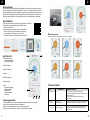
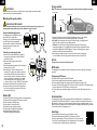
D D
1 2

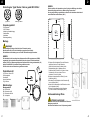
Typ 2 Stecker 3-Phasen Typ 2 Buchse
Abb.2 Abb.3
Abb.4 Abb.5
Abb.6
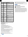
A B C D
Abb.1
200 mm
min
200 mm
min
200 mm
min
1200 - 1400 mm
1
2
3
5
4
Darstellung der Type2 Stecker / Buchse gemäß IEC 62196-2
Verpackungsinhalt:
• EV-Ladestation
• 2x RFID-Karten
• Material zur Wandbefestigung
• Gehäuseöner
• Kabelhaken
• Bedienungsanleitung
Montage
WARNUNG!
Ein beschädigtes EV-Ladegerät darf auf keinen Fall montiert werden.
Bitte informieren Sie im Fall einer Beschädigung umgehend Ihren Händler.
Die Installation und Verkabelung muss von einem Fachbetrieb durchgeführt werden.
HINWEIS:
Die Ladestation ist mit einem integrierten allstromsensitiven Dierenzstromsensor (RCMU)
ausgestattet. Jede Ladestation muss zusätzlich über einen eigenen FI-Fehlerstromschutz-
schalter (RCD) Typ A (Bemessungsfehlerstrom 30mA) und einen Leistungsschutzschalter (LS)
Auslöse-Charakteristik C, Nennstrom 25A angeschlossen werden.
Es dürfen keine anderen Verbraucher angeschlossen werden.
Produktübersicht
1. RFID Leser / Status LED
2. Zuleitungskabel
3. Ladekabel
4. Lade-Kontrolltaste
5. Typ2 Stecker
Wandmontage:
Montagezubehör:
A | 4 x Dübel 6x40
B | 4 x Schrauben 9x38
C | 2 x Schrauben M4 4x8
D | 1 x Halteplatte
HINWEIS:
Es wird empfohlen, die Ladestation an einem Ort mit guter Belüftung, ohne direkter
Sonneneinstrahlung und Schutz vor Wind und Regen zu montieren.
Um eine gute Belüftung zu gewährleisten, sollten Sie die Ladestation vertikal und mit
ausreichend Platz montiert werden (Abb.1).
1. Platzieren Sie die Halteplatte (D) an der Stelle einer
tragfähigen Wand, wo Sie die Ladestation
platzieren möchten. Achten Sie hierbei auf die
Mindestabstände (Abb.1). Markieren Sie die
Bohrlöcher (Abb.2). Bohren Sie 4 Löcher mit einem
Durchmesser von 6 mm und einer Tiefe von
mindestens 50 mm in die Wand.
2. Stecken und versenken Sie die Dübel (A) in den
Bohrlöchern (Abb.3).
3. Schrauben Sie die Halteplatte mit den Schrauben (B)
fest an die Wand (Abb.4).
4. Setzen Sie die Ladestation mit der Rückseite von oben
auf die Halteplatte (Abb.5).
5. Fixieren Sie die Ladestation mit den Schrauben
(C) links und rechts an der Halteplatte (Abb.6).
Gehäuseabdeckung önen
STROMSCHLAGGEFAHR!
Stellen Sie sicher, dass die Ladestation beim Önen der
Abdeckung stromlos ist!
Das Önen des Gehäuses ist nur Fachpersonal gestattet!
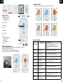
D D
3 4

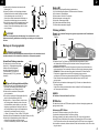
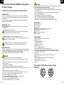
Ladestation
Kabel
Typ 2 Stecker
Ladeanschluss
Abb.7 Abb.8
Abb.10
Abb.9
1
2
2 3
1
4
6
5
1
2
3
1. Entfernen Sie die Schraube auf der Unterseite des
Gerätes (Abb.7/1).
2. Stecken Sie Spitze des im Lieferumfang enthaltenen
Gehäuseöners zwischen beide Geräteteile und hebeln
Sie die Abdeckung nach vorne auf (Abb.7/2).
Gehen Sie wie in Abb.8 beschriebener Reihenfolge vor.
Danach lässt sich Abdeckung nach vorne abnehmen.
3. Zum Schließen setzen Sie die Schutzabdeckung auf das
Gehäuse und drücken Sie, bis die Abdeckung hörbar
einrastet. Fixieren Sie die Abdeckung wieder von unten
mit der Schraube .
ACHTUNG!
Achten Sie unbedingt darauf dass die Abdeckung fest verschlossen ist, um den
Sprtizwasserschutz zu gewährleisten und die Anlage vor eindringen von Feuchtigkeit zu
schützen.
Montage der Versorgungskabel
STROMSCHLAGGEFAHR!
Stellen Sie sicher, dass das Verbindungskabel beim Anschließen an die Ladestation nicht mit
dem Netz verbunden ist! Der Anschluss des Kabels ist nur Fachpersonal gestattet!
Vorinstallierte Zuleitung verwenden:
Die Ladestation ist mit einem 60cm langen
5x4mm² NYY-J Zuleitungskabel ausgestattet.
Schließen Sie das Zuleitungskabel
wie in Abb.9 dargestellt, an einen mit
FI-Schutzschalter (Typ A 30mA) und
Sicherungsautomat (LS C25) gesicherten
Verteiler an.
Eigenes Zuleitungskabel anschließen:
1. Öen Sie wie unter Punkt „Gehäuseabdeckung önen“
beschrieben, die Abdeckung und entfernen Sie das
Flachbandkabel von den Platinen (Abb.10/3).
2. Entfernen Sie das vorhandene Zuleitungskabel
von der Ladestation.
3. Führen Sie das vorbereitete Zuleitungskabel (Abb.10/1)
durch die Gummidurchführung (Abb.10/2).
4. Entfernen Sie ca. 12 mm der Isolation von den Leitern
des Zuleitungskabels. Mehradrige Leiter sollten vorab
mit Aderendhülsen versehen werden, um eine sichere
Verbindung zu gewährleisten. Schließen Sie die Leiter
des Zuleitungskabels wie folgt an die Schraubleiste der
Ladestation an und drehen dieses fest (ca. 4Nm):
L1 Braun | L2 Schwarz | L3 Grau | N Blau | PE Grün-Gelb.
5. Verbinden Sie das Flachbandkabel mit den beiden Platinen (Abb.10/3).
6. Setzen Sie die Schutzabdeckung auf das Gehäuse und
drücken Sie bis die Abdeckung hörbar einrastet.
Fixieren Sie die Abdeckung von unten mit der Schraube.
Status LED
Die Status LED zeigt folgende Zustände der Ladestation an:
1. Rot-Grün-Blau langsamer Wechsel: LED-Selbsttest beim Einschalten
2. Grün konstant an: Standby-Modus
3. Blau konstant an: Mit einem EV verbunden
4. Blau blinkt langsam: Ladevorgang läuft
5. Violett blinkt: Ladevorgang beendet
6. Rot-Gelb blinken abwechselnd: Störung
7. Rot-Blau blinken abwechselnd: Upgrade
Fahrzeug auaden
Hinweis: Das zu ladende Fahrzeug muss geparkt, ausgeschaltet und die Feststellbremse
angezogen sein.
1. Entnehmen Sie den Typ 2 Stecker vom Ladestecker-Halter und schließen Sie ihn an
den Ladeanschluss des Fahrzeugs. Bitte beachten, dass das Fahrzeug auf das Laden
vorbereitet und eingestellt ist.
2. Tastenmodus: Drücken Sie nach dem Einstecken des Steckers die Lade-Kontrolltaste, der
Ladevorgang beginnt. Durch nochmaliges Drücken der Taste wird der Ladevorgang gestoppt.
RFID-Modus: Sie können den Ladevorgang durch Vorhalten der RFID-Karte nach dem
Einstecken des Ladeanschlusses steuern. Der Ladevorgang startet, wenn eine
vorkongurierte RFID Karte den gekennzeichneten Bereich für RFID Anwendung berührt.
Ebenso kann der Ladevorgang durch berühren des Bereiches mit der RFID Karte
gestoppt werden.
3. Entfernen Sie nach beendetem Ladevorgang den Typ 2 Stecker vom Ladeanschluss des
Fahrzeugs entfernen.
Sollten Sie den Stecker nicht herausziehen können, betätigen Sie die Entriegelungstaste
des Fahrzeuges oder Schlüssels.
HINWEIS:
Die Tabelle der Fehlercodes nden Sie auf Seite 8.
RFID-Karten
Die Ladestation wird mit zwei RFID-Karten ausgeliefert, mit denen Ladevorgänge gestartet und
gestoppt werden können.
Anlernen von RFID-Karten
Um weitere RFID-Karten anzulernen, gehen Sie wie folgt vor:
1. Ladestation einschalten und Kabel vom Fahrzeug trennen.
2. Drücken und halten Sie die Lade-Kontrolltaste, bis die LED von grün auf blau wechselt.
3. Neue RFID-Karte (Oine-Betrieb) für mindestens 10 Sekunden an den RFID-Leser halten.
Die LED blinkt und es ertönen sechs akustische Signale. Die RFID-Karte ist nun einsatzbereit.
4. Um den Modus zu beenden, drücken und halten Sie die Lade-Kontrolltaste, bis die LED von blau
auf grün wechselt.
D D
5 6

1
2
3
45 6
7
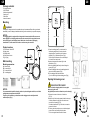
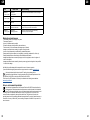
Laden beendet Ladeplan Fehlermedung
Bereit Verbunden Ladevorgang
Status Übersicht
Die aktuellen Zustände der Ladestation werden in der App wie folgt angezeigt:
LED leuchtet nicht - Prüfen Sie, die Stromversorgung und die Verteilung;
- Prüfen Sie die Leistungsschutzschalter und FI-Schutzschalter und
schalten Sie diese ein.
- Prüfen Sie die Elektroverkabelung der Ladestation und
Unterverteilung.
LED blinkt:
1 × rot, 1 × gelb
Störungscode 11:
CP-Spannungsanomalie
- Überprüfen Sie die Verbindung von Ladestecker und EV-Steckdose.
- Ziehen Sie den Ladestecker ab und stecken Sie ihn wieder ein.
LED Fehlercode Fehlerbehandlung
Fehlercode-Tabelle
LED blinkt:
1× rot, 3 × gelb
Störungscode 13:
Unterspannung Eingang
- Prüfen Sie, ob das Eingangskabel zuverlässig angeschlossen ist.
- Stellen Sie sicher, dass die Eingangsspannung der einzelnen
Phasen korrekt ist.
Kommunikation
Die Ladestation verfügt über eine Drahtlose Schnittstelle zu Bluetooth-fahigen Geräten zur Kommuni-
kation in Verbindung mit der EM2GO App „EM2APP“. Die APP ist zur Dateninteraktion über Bluetooth
mit dem Ladegerät verbunden. Sie ermöglicht die Kontrolle des Ladevorgangs und die Einstellung der
Lademethode. Sie können den Status des Ladegerätes und die Echtzeitdaten des Ladevorgangs ver-
folgen und haben die Möglichkeit, Aufzeichnungen, Statistiken über Ladeaufträge usw. einzusehen.
App installieren
1. Aktivieren Sie die Bluetooth-Funktion auf Ihrem Smartphone oder Tablet.
2. Downloaden und installieren Sie die App „EM2APP“ durch
Scannen des QR-Codes.
3. Önen Sie die App und registrieren Sie sich. Klicken Sie auf
das QR-Code Icon der App und scannen Sie den QR Code
auf der Ladestation. Die Ladestation ist nun mit dem
Smart-Gerät verbunden und kann darüber gesteuert werden.
App Übersicht
1. Ladestation Auswahl:
- Ladestation hinzufügen
- Ladestation Auswählen
2. Start/Stop-Button
3. Aktuelle Einstellung
4. Statistik
5. Benachrichtigungen
6. Proleinstellung
7. Menü:
- Reservierung/Ladeplan
- Freigabe-Ladegerät
- Ladedatensatz
- Benutzerverwaltung
- Einstellung
Ladevorgang starten
1. Verbinden Sie den Typ 2 Stecker der Ladestation mit dem Ladeanschluss des Fahrzeugs.
2. Stellen Sie den Ladestrom über den Schieberegler ein.
3. Klicken Sie auf den Start-Button der App, der Ladevorgang startet.
4. Klicken Sie auf den Start-Button der App um den Ladevorgang zu beenden.
D D
7 8

LED blinkt:
1× rot, 5 × gelb
Störungscode 15:
Überhitzungsschutz
- Prüfen Sie, ob die Ladestation abgedeckt oder in einer Umgebung
mit hohen Temperaturen installiert ist.
LED blinkt:
1× rot, 6 × gelb
Störungscode 16:
Energiezähler gestört
- Schalten Sie das Gerät aus und starten Sie es neu.
LED blinkt:
1× rot, 7 × gelb
Störungscode 17:
Fehlerstromerkennung
- Prüfen Sie Ladestecker/Buchse und Kabel auf Beschädigungen und
Feuchtigkeit.
- Ziehen Sie den Ladestecker ab und stecken Sie ihn wieder ein.
LED blinkt:
1× rot, 8 × gelb
Störungscode 18
Leistungsabfall
- Prüfen Sie Ladestecker/Buchse und Kabel auf Beschädigungen.
LED blinkt:
1× rot, 9 × gelb
Störungscode 19
Überstromerkennung
- Prüfen Sie, ob der Ladestecker richtig angeschlossen ist.
- Prüfen Sie die Funktion des On-Board Chargers des Fahrzeugs.
- Prüfen Sie die Einstellung des Ausgangsstroms.
LED blinkt:
2 × rot, 1 × gelb
Störungscode 21
EV-Kommunikation
Zeitüberschreitung
- Ziehen Sie den Ladeanschluss ab und stecken Sie ihn wieder ein.
LED blinkt:
2 × rot, 2 × gelb
Fehlercode 22
EV nicht unterstützt
- Dieses EV entspricht nicht den IEC-Normen und kann nicht
aufgeladen werden.
LED blinkt:
2 × rot, 3 × gelb
Störungscode 23
Reials-Fehler
- Das Gerät ist beschädigt und muss zur Reparatur ins Werk
geschickt werden.
LED blinkt:
2 × rot, 4 × gelb
Störungscode 24:
RCMU-Fehler
- Das Gerät ist beschädigt und muss zur Reparatur ins Werk
geschickt werden.
LED blinkt:
2 × rot, 5 × gelb
Störungscode 25:
Fehler Schutzleiter
- Die Ladestation ist nicht oder nicht korrekt geerdet;
das Eingangsstromkabel muss überprüft werden.
LED blinkt:
2 × rot, 6 × gelb
Störungscode 26:
PEN-Leckageschutz
- Prüfen Sie, ob der Ladestecker und sein Kabel undicht sind.
- Wiederherstellen, nachdem Sie den Adapter herausgezogen haben.
LED Fehlercode Fehlerbehandlung
LED blinkt:
1× rot, 4 × gelb
Störungscode 14:
Überspannung am Eingang
- Prüfen Sie, ob das Eingangskabel zuverlässig angeschlossen ist.
- Stellen Sie sicher, dass die Eingangsspannung der einzelnen
Phasen korrekt ist.
Garantie und Wartung
• Die Garantiezeit für dieses Ladegerät beträgt zwei Jahre.
• Die Garantie verfällt wenn:
• Kein Kaufbeleg vorgelegt werden kann.
• Die vom Hersteller angegebene Garantiezeit überschreiten ist.
• Die Gebrauchs-, Wartungs- und Lagerungsanweisungen nicht befolgt werden.
• Schäden oder Fehlfunktionen durch das Eindringen von Fremdkörpern verursacht werden.
• Bei Reparatur, Demontage oder Modikation durch unbefugte Personen.
• Schäden durch höhere Gewalt (wie Blitzschlag, Überspannung, Erdbeben, Feuer, Überschwemmung
usw.) verursacht wurden.
• Schäden und Funktionsstörungen durch andere vermeidbare äußere Faktoren verursacht werden.
• Schäden und Funktionsstörungen durch unsachgemäßen Gebrauch der Ausrüstung verursacht
werden, wie z.B. das Eindringen von Wasser oder anderen Flüssigkeiten.
• Schäden und Funktionsstörungen durch die Netzstromversorgung und einer Spannung verursacht
werden, die nicht für die Verwendung mit dem Ladegerät speziziert ist.
Bei falscher Bedienung wird keine Haftung für eventuelle Schäden übernommen.
Falls Sie Technischen Support benötigen, kontaktieren Sie bitte unser Support-Team über unsere
Website www.em2go.de.
D D
9 10
Hiermit Erklären wir, dass dieses Gerät die CE Kennzeichnung gemäß den
Bestimmungen und Vorgaben trägt. Es entspricht somit den Grundlegenden Anforderungen
der RED-Richtlinie 2014/53/EU, sowie der RoHS-Richtlinie 2011/65/EU.
Der vollständige Text der EU-Konformitätserklärung ist unter der folgenden Internetadresse verfügbar:
www.em2go/Konfo
Hinweis zum Umweltschutz:
Ab dem Zeitpunkt der Umsetzung der europäischen Richtlinie 2011/65/EU in
nationales Recht gilt folgendes: Elektrische und elektronische Geräte dürfen
nicht mit dem Hausmüll entsorgt werden.
Der Verbraucher ist gesetzlich verpichtet, elektrische und elektronische Geräte am Ende
ihrer Lebensdauer an den dafür eingerichteten, öentlichen Sammelstellen oder an die Verkaufsstelle
zurückzugeben. Einzelheiten dazu regelt das jeweilige Landesrecht. Das Symbol auf dem Produkt, der
Gebrauchsanleitung oder der Verpackung weist auf diese Bestimmungen hin. Mit der Wiederverwer-
tung, der stoichen Verwertung oder anderer Formen der Verwertung von Altgeräten leisten Sie einen
wichtigen Beitrag zum Schutz unserer Umwelt. In Deutschland gelten oben genannte Entsorgungsre-
geln, laut Batterieverordnung, für Batterien und Akkus entsprechend. (EU) 2015/863.

Type 2 Plug 3-Phase Type 2 Socket
Thank you for choosing the EM2GO charging station
for electric vehicles.
With this smart wallbox, you have chosen a high-precision EV charger equipped with many
safetyrelated protection devices, which guarantees all-round carefree charging of your vehicle.
Important Notice:
This manual contains important instructions and information to be observed during installation,
operation and maintenance. Read all safety information and warnings in this manual to be aware of
potential hazards.
This manual is intended for installation and maintenance personnel as well as end customers.
Keepthis user manual in a safe place.
Safety signs used
The following warning, command and information signs are used in this manual, on and in the
EV charging station.
CAUTION: Warning of electrical hazards.
This sign is intended to alert the user that serious injury or substantial property damage
may result if the equipment is not operated as instructed.
WARNING: Warning of a hazardous location or dangerous situation.
This sign is intended to alert the user that minor injury or property damage may result if the
equipment is not operated as instructed.
CAUTION: Do not touch with hands when electrostatic discharge is possible. Indicates
the possible consequences of touching electrostatically sensitive components.
IMPORTANT NOTICE:
According to §19 NAV of March 21, 2019, the operation of charging devices for electric vehicles must
be reported to the responsible grid operator before use (from 11 KW), as well as before installation
(from 22 KW). This can also be done by the commissioned electrical installer.
Please contact your electricity provider by phone or online for more information.
WARNING!
When using electrical products, always observe these basic precautions.
• Do not install or use the charger near explosive, corrosive or ammable materials, chemicals or
vapors.
• The charger may only be installed on non-combustible surfaces such as concrete, and at least
120cm above the oor.
• The charger must be safely grounded.
• Turn o the power to the charger before assembling or servicing the charger.
• The device is designed only for vehicles compatible with the IEC 62196 standard for charging
modes.
• Do not use the charger if it is defective or has visible damage
• Do not attempt to önen, disassemble, repair, tamper with or modify the device. If you have
any questions or need repairs, contact our customer service department.
• Do not use the charger when you are in the vehicle.
• Do not use the charger when exposed to heavy rain, snow or inclement weather.
• Always exercise caution when transporting the charger.
• Do not touch the charging terminal with sharp metallic objects
• Do not pull the charging cable with force or over sharp objects.
WARNING!
The device may only be installed, adjusted and serviced by qualied persons familiar with the cons-
truction and operation of this type of electrical equipment.
Failure to observe this precaution can result in serious injury or even death.
• Incorrect installation and testing of the charger can possibly lead to damage. No liability is accepted
for the resulting damage.
• Ensure that the charging cable is correctly positioned during the charging process and cannot
be stepped on, damaged or stressed.
• Check wire diameter according to local electrical requirements.
• Switch o the corresponding power supply before starting the installation.
• The charger must be installed and commissioned by qualied personnel.
• Before installation, the supply cable and house connection values must be checked.
Abbreviations:
A | ampere, unit of current
V | volt, unit of voltage
EV | electric vehicle
EVSE | Equipment for the supply of EV according to IEC61851-1
RFID | Radio Frequency Identication Card
IP | Protection class
RCMU | Residual current monitoring unit
MCB | Circuit breaker
Technical data:
• Operating voltage: 400V AC ±10%, 50-60 Hz, 3-phase
• Operating current: 16A
• Max. Output power Typically 11 kW
• Housing: IP65, splash-proof
• Input terminals: L1, L2, L3, N, PE
• Connection: Type 2 plug
• IEC 61851-1 Charging mode: Mode 3
• Communication interfaces: Communication interface: BT, RFID
• Safety devices: Overvoltage protection, overtemperature, over/undervoltage, overcurrent,
protection against fault currents (RCMU 30mA AC+6mA DC) and protective conductor faults
for TN system (TN-C, TN-S and TN-C-S).
• Display: LED
• Structure: CE standards IEC 61851-1 IEC 62196-2:2016, IEC 60364-7-722
• Material: PC+ASA
• Connection length: type 2 cable 5 meters, supply cable 60cm (5x4mm²)
• Operating temperature: -30 to +55 °C
• Dimensions: 180 mm × 180 mm × 64.5 mm
• Weight: 4kg
Representation of Type2 plug / socket according to
IEC 62196-2
GB GB
11 12

A B C D
1
2
3
5
4
Fig.1
200 mm
min
200 mm
min
200 mm
min
1200 - 1400 mm
Fig.2 Fig.3
Fig.4 Fig.5
Fig.6
Fig.7 Fig.8
2 3
1
4
6
5
1
2
GB GB
13 14
Package contents:
• EV charging station
• 2x RFID cards
• Wall mounting material
• Opening tool
• Cable hook
• Instruction manual
Mounting
WARNING!
A damaged EV charger must not be mounted under any circumstances.Please inform your dealer
immediately in case of damage. Installation and wiring must be carried out by a specialist company.
NOTICE:
The charging station is equipped with an integrated all-current sensitive dierence current
sensor (RCMU). Each charging station must also be connected via its own residual current
device (RCD) type A (rated residual current 30mA) and a circuit breaker (CB) tripping
characteristic C, rated current 25A. No other consumers may be connected.
Product overview
1. RFID Reader / Status LED
2. Supply cable
3. Charging cable
4. Charge control button
5. Type 2 plug
Wall mounting
Mounting accessories:
A | 4 x dowel 6x40
B | 4 x screws 9x38
C | 2 x screws M4 4x8
D | 1 x retaining plate
NOTICE:
It is recommended to install the charging station in a place with good ventilation, out of direct
sunlight and protected from wind and rain.
To ensure good ventilation, you should mount the charging station vertically and with
sucient space (Fig.1).
1. Place the retaining plate (D) at the location of a
load-bearing wall where you want to place the
charging station. Pay attention to the minimum
distances (Fig.1). Mark the drill holes (Fig.2).
Drill 4 holes with a diameter of 6 mm and a depth
of at least 50 mm into the wall.
2. Insert and countersink the dowels (A) into the
drilled holes (Fig.3).
3. Screw the retaining plate rmly to the wall using the
screws (B) (Fig.4).
4. Place the charging station on the retaining plate with
the rear side facing upwards (Fig.5).
5. Fix the charging station with the screws
(C) on the left and right of the retaining plate (Fig.6).
Opening the housing cover
RISK OF ELECTRIC SHOCK!
Make sure that the charging station is de-energized
when opening the cover!
Only qualied personnel are allowed to open the housing!
1. Remove the screw on the bottom of the device
(Fig.7/1).
2. Insert the tip of the housing opener included in the scope
of delivery between the two parts of the device and
lever the cover forward (Fig.7/2).
Proceed as described in Fig.8. After that, cover can be
removed to the front.
3. To close, place the protective cover on the housing and
press until the cover audibly clicks into place.
Fix the cover again from below with the screw.

Fig.9
Fig.10
1
2
3
Charging station
Cable
Type 2 plug
Charging port
GB GB
15 16
ATTENTION!
Make absolutely sure that the cover is tightly closed to ensure splash water protection and to
protect the system from moisture penetration.
Mounting the supply cables
RISK OF ELECTRIC SHOCK!
Make sure that the connection cable is not connected to the mains when connecting it to the
charging station! Only qualied personnel are allowed to connect the cable!
Use pre-installed supply cable:
The charging station is equipped with a 60cm
long 5x4mm² NYY-J supply cable.
As shown in Fig.9, connect the supply cable
to an RCD (type A 30mA) equipped and
the fuse must be connected to the distribution
board protected by an automatic circuit
breaker (CB C25).
Connect your own supply cable:
1. Open the cover as described under „Opening the
housing cover“ and remove the ribbon cable from
the boards (Fig.10/3).
2. Remove the existing supply cable from the
charging station.
3. Feed the prepared supply cable (Fig.10/1) through the
rubber grommet (Fig.10/2).
4. Remove approx. 12 mm of insulation from the
conductors of the supply cable. Multicore conductors
should be tted with wire end ferrules in advance to
ensure a secure connection. Connect the conductors
of the supply cable to the screw bar of the charging
station as follows and screw it tight (approx. 4Nm):
L1 Brown | L2 Black | L3 Gray | N Blue | PE Green Yellow.
5. Connect the ribbon cable to the two boards (Fig.10/3).
6. Place the protective cover on the housing and press
until the cover audibly clicks into place. Fix the cover
from below with the screw.
Status LED
The status LED indicates the following states of the charging station:
1. Red-green-blue slow change: LED self-test at power-up
2. Green constantly on: Standby mode
3. Blue constant on: Connected to an EV
4. Blue ashes slowly: charging in progress
5. Purple ashing: Charging process completed
6. Red-yellow ashing alternately: Fault
7. Red-blue ashing alternately: Upgrade
Charge vehicle
Note: The vehicle to be charged must be parked, switched o and the parking brake applied.
1. Remove the type 2 plug from the charging plug holder and connect it to the vehicle‘s
charging port. Please note that the vehicle is prepared and set for charging.
2. Key mode: Press the charge control key after inserting the plug, the charging process
starts. Press the key again to stop the charging process.
RFID mode: You can control the charging process by holding the RFID card after
inserting the charging port. The charging process starts when a pre-congured RFID card
touches the designated area for RFID application. Likewise, the charging process can be
stopped by touching the area with the RFID card.
3. After charging is complete, remove the Type 2 plug from the vehicle‘s charging port.
If you are unable to pull out the plug, press the unlock button on the vehicle or key.
NOTICE:
The table of error codes can be found on page 18.
RFID cards
The charging station is supplied with two RFID cards that can be used to start and stop charging
processes.
Programming RFID cards
Proceed as follows to program additional RFID cards:
1. Switch on the charging station and disconnect the cable from the vehicle.
2. Press and hold the charge control button until the LED changes from green to blue.
3. Hold new RFID card (oine mode) to RFID reader for at least 10 seconds. The LED ashes and six
acoustic signals sound. The RFID card is now ready for use.
4. To exit the mode, press and hold the charge control button until the LED changes from blue to
green.
Communication
The charging station has a wireless interface to Bluetooth enabled devices for communication in
conjunction with the EM2GO App „EM2APP“. The app is connected to the charger via Bluetooth for
data interaction. It allows you to control the charging process and set the charging method. You can
follow the status of the charger and the real time data of the charging process and have the possibility
to view records, statistics of charging jobs, etc.
Install app
1. Activate the Bluetooth function on your smartphone or tablet.
2. Download and install the app „EM2APP“ by scanning the QR code.
3. Open the app and register. Click on the QR code icon of the app and scan
the QR code on the charging station. The charging station is now connected
to the Smart device connected and can be controlled via it.

1
2
3
45 6
7
Charging nished Charging schedule Fault
Ready Connected Charging
LED does not light - Check the power supply and distribution;
- Check the circuit breakers and RCDs and turn them on.
- Check the electrical wiring of the charging station and
sub-distribution
LED ashes:
1 × red, 1 × yellow
Fault code 11:
CP voltage anomaly
- Check the connection of the charging plug and EV socket.
- Unplug the charging plug and plug it back in.
LED Error code Error handling
Error code table
LED ashes:
1× red, 3 × yellow
Fault code 13:
Input undervoltage
- Check that the input cable is reliably connected.
- Make sure that the input voltage of each phase is correct.
LED ashes:
1× red, 5 × yellow
Fault code 15:
Overheating protection
- Check if the charging station is covered or installed in an
environment with high temperatures.
LED ashes:
1× red, 6 × yellow
Fault code 16:
Energy meter disturbed
- Switch o the device and restart it.
LED ashes:
1× red, 4 × yellow
Fault code 14:
Input overvoltage
- Check that the input cable is reliably connected.
- Make sure that the input voltage of each phase is correct.
LED ashes:
1× red, 7 × yellow
Fault code 17:
Fault current detection
- Check charging plug/socket and cable for damage and moisture.
- Unplug the charging plug and plug it back in.
LED ashes:
1× red, 8 × yellow
Fault code 18
Power loss
- Check charging plug/socket and cable for damage.
LED ashes:
1× red, 9 × yellow
Fault code 19
Overcurrent detection
- Check that the charging plug is connected correctly.
- Check the function of the vehicle‘s on-board charger.
- Check the setting of the output current.
LED ashes:
2 × red, 1 × yellow
Fault code 21
EV communication timeout
- Unplug the charging connector and plug it back in.
GB GB
17 18
App overview
1. Charging station selection:
- Add charging station
- Select charging station
2. Start/Stop button
3. Current setting
4. Statistics
5. Notications
6. Prole setting
7. Menu:
- Reservation/loading plan
- Release charger
- Load data set
- User management
- Setting
Start charging process
1. Connect the type 2 plug of the charging station to the charging port of the vehicle.
2. Set the charging current via the slider.
3. Click the start button of the app, the loading process starts.
4. Click on the start button of the app to nish the loading process.
Status overview
The current states of the charging station are displayed in the app as follows:

LED ashes:
2 × red, 2 × yellow
Fault code 22
EV not supported
- This EV does not meet IEC standards and cannot be charged.
LED ashes:
2 × red, 3 × yellow
Fault code 23
Relay error
- The device is damaged and must be sent to the factory for repair.
LED ashes:
2 × red, 4 × yellow
Fault code 24:
RCMU error
- The device is damaged and must be sent to the factory for repair.
LED ashes:
2 × red, 5 × yellow
Fault code 25:
Protective conductor fault
- The charging station is not grounded or not grounded
correctly; the input power cable must be checked.
LED ashes:
2 × red, 6 × yellow
Fault code 26:
PEN leakage protection
- Check if the charging plug and its cable are leaking.
- Restore after you pull out the adapter.
LED Error code Error handling
GB GB
19 21
Warranty and maintenance
• The warranty period for this charger is two years.
• The warranty expires if:
• No proof of purchase can be provided.
• Exceed the warranty period specied by the manufacturer.
• The instructions for use, maintenance and storage are not followed.
• damage or malfunctions are caused by the ingress of foreign bodies.
• In case of repair, disassembly or modication by unauthorized persons.
• Damage caused by force majeure (such as lightning, overvoltage, earthquake, re, ood, etc.).
• Damage and malfunctions are caused by other avoidable external factors.
• damage and malfunctions are caused by improper use of the equipment, such as the ingress of
water or other liquids.
• damage and malfunction are caused by the mains power supply and a voltage that is not specied
for use with the charger.
No liability for possible damage will be accepted in the event of incorrect operation.
If you need technical support, please contact our support team via our website www.em2go.de.
We hereby declare that this device has the CE marking in accordance with the
regulations and specications. It therefore complies with the Essential Requirements of the
RED Directive 2014/53/EU, as well as the RoHS Directive 2011/65/EU.
The full text of the EU Declaration of Conformity is available at the following Internet address:
www.em2go.de/Konfo
Note on environmental protection:
From the date of implementation of the European Directive 2011/65/EU into national law, the
following applies: Electrical and electronic equipment must not be disposed of with household
waste. The consumer is obliged by law to return electrical and electronic equipment at the end
of its service life to the öentlich collection points set up for this purpose or to the point of sale.
returned. Details are regulated by the respective national law. The symbol on the product, the
operating instructions or the packaging indicates these regulations. By recycling, material recovery or
other forms of recovery of old devices, you are making an important contribution to the protection of
our environment.

V1_10_2022
Improvement and changes of the technical specications and other data’s could be made without prior notice. Registered trademarks are the property of their respective owners.
EM2GO ist eine Marke der D-Parts GmbH
D-Parts GmbH • Birkenweiher Str. 16 • 63505 Langenselbold, Germany / www.em2go.de
-
 1
1
-
 2
2
-
 3
3
-
 4
4
-
 5
5
-
 6
6
-
 7
7
-
 8
8
-
 9
9
-
 10
10
-
 11
11
-
 12
12


in anderen Sprachen
- English: EM2GO EMB011AC1RW Owner's manual
Verwandte Artikel


Andere Dokumente
-
 PATONA WB1-11 Benutzerhandbuch
-
fontastic EM2GO Benutzerhandbuch
-
 ZAPTEC ZapCharger Pro Benutzerhandbuch
-
VESTEL EVCO4 Series Benutzerhandbuch
-
-
-
-
-
-
 Alfen Eve Single Pro-line DE Benutzerhandbuch


