GOK Operating manuel Adapter Bedienungsanleitung
- Typ
- Bedienungsanleitung

Originalanleitung / Artikel-Nr. 56 080 50 c Ausgabe 07.2023 / Ersatz für Ausgabe 07.2016
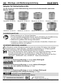
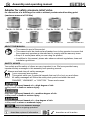
Montage- und Bedienungsanleitung
Adapter für Sicherheitsventile
für den Anschluss einer Abblaseleitung mit und ohne Sollbruchstelle (maximales
Moment 300 Nm)
Bestell-Nr. 56 083 00
Bestell-Nr. 56 086 10
Bestell-Nr. 56 081 10
Bestell-Nr. 56 080 01
Bestell-Nr. 56 080 00
Bestell-Nr. 56 080 10
Bestell-Nr. 56 081 00
Bestell-Nr. 56 086 00
ZU DIESER ANLEITUNG
•Diese Anleitung ist ein Teil des Produktes.
•Für den bestimmungsgemäßen Betrieb und zur Einhaltung der Gewährleistung
ist diese Anleitung zu beachten und dem Betreiber auszuhändigen.
•Während der gesamten Benutzung aufbewahren.
•Zusätzlich zu dieser Anleitung sind die nationalen Vorschriften, Gesetze und
Installationsrichtlinien zu beachten.
SICHERHEITSBEZOGENE HINWEISE
Ihre Sicherheit und die Sicherheit anderer ist uns sehr wichtig. Wir haben viele wichtige
Sicherheitshinweise in dieser Montage- und Bedienungsanleitung zur Verfügung gestellt.
Lesen und beachten Sie alle Sicherheitshinweise sowie Hinweise.
Dies ist das Warnsymbol. Dieses Symbol warnt vor möglichen Gefahren, die den
Tod oder Verletzungen für Sie und andere zur Folge haben können. Alle
Sicherheitshinweise folgen dem Warnsymbol, auf dieses folgt entweder das Wort
„GEFAHR", „WARNUNG" oder „VORSICHT". Diese Worte bedeuten:
bezeichnet eine Personengefährdung mit einem hohen Risikograd.
Hat Tod oder eine schwere Verletzung zur Folge.
bezeichnet eine Personengefährdung mit einem mittleren Risikograd.
Hat Tod oder eine schwere Verletzung zur Folge.
bezeichnet eine Personengefährdung mit einem niedrigen Risikograd.
Hat eine geringfügige oder mäßige Verletzung zur Folge.
bezeichnet einen Sachschaden.
Hat eine Beeinflussung auf den laufenden Betrieb.
bezeichnet eine Information
bezeichnet eine
Handlungsaufforderung

Adapter für Sicherheitsventile
2 / 8
Artikel-Nr. 56 080 50 c
PRODUKTBEZOGENE SICHERHEITSHINWEISE
Ausströmendes Flüssiggas (Kategorie 1):
•ist extrem entzündbar
•kann zu Explosionen führen
•schwere Verbrennungen bei direktem Hautkontakt
Verbindungen regelmäßig auf Dichtheit prüfen!
Bei Gasgeruch und UndichtheitFlüssiggasanlage sofort außer Betrieb nehmen!
Zündquellen oder elektrische Geräte außer Reichweite halten!
Entsprechende Gesetze und Verordnungen beachten!
Bestimmungsgemäße Verwendung in explosionsgefährdeten Bereichen!
Bildung einer gefährlichen explosionsfähigen Atmosphäre kann nicht
ausgeschlossen werden.
Erforderliche Schutzmaßnahmen durchführen nach:
DE: Betriebssicherheitsverordnung (ATEX Betriebsrichtlinie 1999/92/EG).
Wahrscheinlichkeit explosionsfähiger Atmosphäre beurteilen!
Vorhandensein von Zündquellen beurteilen!
Mögliche Auswirkungen von Explosionen beurteilen!
Explosionsgefährdeten Bereiche in Zonen einteilen und Maßnahmen treffen!
Verwendung im explosionsgefährdeten Bereich Ex-Zone 0 nicht zulässig!
Kann zu Explosion oder schweren Verletzungen führen.
Einbau außerhalb der Ex-Zone 0!
Verwendung im explosionsgefährdeten Bereich Ex-Zone 1 oder 2 ist möglich.
Einbau vom Fachbetrieb, der auf dem Gebiet des Explosionsschutzes befähigt ist
(ATEX Betriebsrichtlinie 1999/92/EG).
Einbau innerhalb der festgelegten Ex-Zone 1 oder 2!
BESTIMMUNGSGEMÄSSE VERWENDUNG
Betriebsmedien
•Flüssiggas (Gasphase)
Eine Liste der Betriebsmedien mit Angabe der Bezeichnung,
der Norm und des Verwendungslandes erhalten Sie im Internet unter
www.gok.de/liste-der-betriebsmedien.
Nach TRF Anhang B, müssen die Adapter, die mit einer Sollbruchstelle
versehen sind, ein Moment von maximal 300 Nm übertragen.
MONTAGE
Vor der Montage ist das Produkt auf Transportschäden und Vollständigkeit zu prüfen.
Bei Arbeiten am und um den Behälter, Schutzzone beachten!
Kann zu Explosion oder schweren Verbrennungen führen!
Löten und Bohren nur außerhalb des explosionsgefährdeten Bereichs!
Schrauben innerhalb des explosionsgefährdeten Bereichs, nur mit
Handschraubendreher befestigen!
Die Verbindung zwischen Sicherheitsventil und Adapter muss lösbar sein!
Adapter auf Sicherheitsventil schrauben (ohne Schraubensicherung).

Adapter für Sicherheitsventile
3 / 8
Artikel-Nr. 56 080 50 c
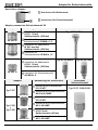
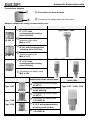
Anschlüsse Adapter
Anschluss für Abblaserohr
Anschluss für Sicherheitsventil
Adapter passend zu Sicherheitsventil SV
Adapter
Abmessung der Anschlüsse
Passendes Sicherheitsventil
56 083 00
Anschluss für Abblaserohr
IG G 1 1/2 mit
Sollbruchstelle (300 Nm)
Typ A8684/ 8684
Anschluss für
Sicherheitsventil IG M48 x 1,5
56 087 20
Anschluss für Abblaserohr
Ø54,3 mm mit
Sollbruchstelle (300 Nm)
Anschluss für
Sicherheitsventil IG M48 x 1,5
56 086 10
Anschluss für Abblaserohr
IG G 1 1/2 mit
Sollbruchstelle (300 Nm)
Typ ATSV-A5005
Typ ATSV 5000
Anschluss für Sicherheitsventil
AG M54 x 2
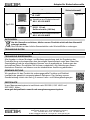
Adapter
Abmessung der Anschlüsse
Passendes
Sicherheitsventil
Typ 3127
56 080 01
Anschluss zum Abblaserohr
IG 1/2 NPT
Typ 3127/ 3128/ 3129/
Anschluss am Sicherheitsventil
AG 3/4-20 UNEF
Typ 3128
+
Typ 3129
56 080 00
Anschluss zum Abblaserohr
IG 1/2 NPT
Anschluss am Sicherheitsventil
AG 1-20 UNEF
56 080 10
Anschluss zum Abblaserohr
IG G 1/2 mit
Sollbruchstelle (90 Nm)
Anschluss am Sicherheitsventil
AG 1-20 UNEF

Adapter für Sicherheitsventile
4 / 8
Artikel-Nr. 56 080 50 c
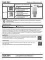
Adapter
Abmessung der Anschlüsse
Passendes
Sicherheitsventil
Typ 3131
56 081 00
Anschluss zum Abblaserohr:
IG 1 NPT
Anschluss am Sicherheitsventil
AG 1 9/16-20 UNEF
56 086 00
Anschluss zum Abblaserohr
IG G 1 1/2 mit
Sollbruchstelle (180 Nm)
Anschluss am Sicherheitsventil
AG 1 9/16-20 UNEF
ENTSORGEN
Um die Umwelt zu schützen, dürfen unsere Produkte nicht mit dem Hausmüll
entsorgt werden.
Das Produkt ist über örtliche Sammelstellen oder Wertstoffhöfe zu entsorgen.
TECHNISCHE DATEN
Gehäusewerkstoff
Messing CW617N
TECHNISCHE ÄNDERUNGEN
Alle Angaben in dieser Montage- und Bedienungsanleitung sind die Ergebnisse der
Produktprüfung und entsprechen dem derzeitigen Kenntnisstand sowie dem Stand der
Gesetzgebung und der einschlägigen Normen zum Ausgabedatum. Änderungen der
technischen Daten, Druckfehler und Irrtümer vorbehalten. Alle Abbildungen dienen
illustrativen Zwecken und können von der tatsächlichen Ausführung abweichen.
GEWÄHRLEISTUNG
Wir gewähren für das Produkt die ordnungsgemäße Funktion und Dichtheit
innerhalb des gesetzlich vorgeschriebenen Zeitraums. Der Umfang unserer
Gewährleistung richtet sich nach § 8 unserer Liefer- und Zahlungsbedingungen.
ZERTIFIKATE
Unser Managementsystem ist zertifiziert nach ISO 9001, ISO 14001 und
ISO 50001, siehe:
www.gok.de/qualitaets-umwelt-und-energiemanagementsystem.
Regler- und Armaturen-Gesellschaft mbH & Co. KG
Obernbreiter Straße 2-18 • 97340 Marktbreit / Germany
Tel.: +49 9332 404-0 • Fax: +49 9332 404-43
E-Mail: info@gok-online.de • www.gok.de • www.gok-blog.de
Typ 3131

5 / 8
Translation of the original operating instructions / Part no. 56 080 50 c Version 07.2023 / Replaces version 07.2016
Adapter for safety pressure relief valve
for connection of a discharge line with or without predetermined breaking point
(maximum moment of 300 Nm)
Part No. 56 083 00
Part No. 56 086 10
Part No. 56 081 10
Part No. 56 080 01
Part No. 56 080 00
Part No. 56 080 10
Part No. 56 081 00
Part No. 56 086 00
ABOUT THE MANUAL
•This manual is part of the product.
•This manual must be observed and handed over to the operator to ensure that
the component operates as intended and to comply with the warranty terms.
•Keep it in a safe place while you are using the product.
•In addition to this manual, please also observe national regulations, laws and
installation guidelines.
SAFETY ADVICE
Your safety and the safety of others are very important to us. We have provided many
important safety messages in this assembly and operating manual.
Always read and obey all safety messages.
This is the safety alert symbol.
This symbol alerts you to potential hazards that can kill or hurt you and others.
All safety messages will follow the safety alert symbol and either the word
“DANGER”, “WARNING”, or “CAUTION”. These words mean:
describes a personal hazard with a high degree of risk.
May result in death or serious injury.
describes a personal hazard with a medium degree of risk.
May result in death or serious injury.
describes a personal hazard with a low degree of risk.
May result in minor or moderate injury.
describes material damage.
Has an effect on ongoing operation.
describes a piece of information describes a call to action
Assembly and operating manual

Adapter für Sicherheitsventile
6 / 8
Artikel-Nr. 56 080 50 c
PRODUCT-RELATED SAFETY ADVICE
Escaping liquid petroleum gas (category 1):
•is highly flammable
•may cause explosions
•severe burns in case of direct skin contact
Regularly check connections for leak-tightness.
If you smell gas or detect a leak, shut the system down immediately.
Keep ignition sources and electrical devices out of reach.
Observe applicable laws and regulations.
Intended use in potentially explosive areas.
The formation of a hazardous explosive atmosphere cannot be ruled out.
Take the required protective measures according to:
GER: Ordinance on Industrial Safety and Health, EC: Directive 1999/92/EC!
Assess the likelihood of explosive atmospheres.
Assess the presence of sources of ignition.
Assess possible impacts of explosions.
Divide potentially explosive areas into zones and take measures.
Must not be used in potentially explosive ex-zone 0!
Can cause an explosion or serious injuries.
Installation outside ex-zone 0.
May be used in potentially explosive ex-zones 1 or 2.
Installation by a company that specialises in explosion protection
(ATEX Directive 1999/92/EC).
Installation within defined ex-zones 1 or 2.
INTENDED USE
Operating media
•LPG (gas phase)
You will find a list of operating media with descriptions, the relevant
standards and the country in which they are used in the Internet at
www.gok.de/liste-der-betriebsmedien.
According to TRF, Appendix B, adapters with a predetermined breaking point
must transmit a maximum moment of 300 Nm.
ASSEMBLY
Before assembly, check that the product is complete and has not suffered any damage during
transport.
Observe the protective zone when working on or near the tank!
Can cause an explosion or serious burns!
Solder and drill only outside the potentially explosive zone!
If screwing within the potentially explosive zone, use only a manual screwdriver!
It must be possible to separate the safety pressure relief valve and the adapter.
Screw the adapter on to the safety pressure relief valve (without locking device).

Adapter für Sicherheitsventile
7 / 8
Artikel-Nr. 56 080 50 c
Connections Adapter
Connection for blow-off pipe
Connection for safety pressure relief valve
Adapter suitable for safety pressure relief valve
Adapter
Dimensions of the connections
Suitable safety pressure relief valve
56 083 00
Connection for blow-off pipe
G 1 1/2 F with
predetermined breaking
point (300 Nm)
Type A8684 / 8684
Connection for safety
pressure relief valve
M48 x 1.5 F
56 087 20
Connection for blow-off pipe
Ø54,3 with predetermined
breaking point (300 Nm)
Connection for safety
pressure relief valve
M48 x 1.5 F
56 086 10
Connection for blow-off pipe
G 1 1/2 F with
predetermined breaking
point (300 Nm)
Type ATSV-A5005
Type ATSV5000
Connection for safety valve
M54 x 2 M
Adapter
Dimensions of the connections
Suitable safety pressure
relief valve
Type 3127
56 080 01
Connection for blow-off pipe
1/2 NPT F
Type 3127 / 3128 / 3129
Connection for safety valve
3/4-20 UNEF M
Type 3128
+
Type 3129
56 080 00
Connection for blow-off pipe
1/2 NPT F
Connection for safety valve
1-20 UNEF M
56 080 10
Connection for blow-off pipe
G 1/2 F with predetermined
breaking point (90 Nm)
Connection for safety valve
1-20 UNEF M

Adapter für Sicherheitsventile
8 / 8
Artikel-Nr. 56 080 50 c
Adapter
Dimensions of the connections
Suitable safety pressure
relief valve
Type 3131
56 081 00
Connection for blow-off pipe:
G1 NPT F
Connection for safety valve
1 9/16-20 UNEF M
56 086 00
Connection for blow-off pipe
G 1 1/2 F with
predetermined breaking
point (180 Nm)
Connection for safety valve
1 9/16-20 UNEF M
DISPOSAL
To protect the environment, our products may not be disposed of along with
household waste.
The product must be disposed of via a local collection station or a recycling station.
TECHNICAL DATA
Housing material
Brass CW617N
TECHNICAL CHANGES
All the information contained in this assembly and operating manual is the result of product
testing and corresponds to the level of knowledge at the time of testing and the relevant
legislation and standards at the time of issue. We reserve the right to make technical changes
without prior notice. Errors and omissions excepted. All figures are for illustration purposes
only and may differ from actual designs.
WARRANTY
We guarantee that the product will function as intended and will not leak during
the legally specified period. The scope of our warranty is based on Section 8 of
our terms and conditions of delivery and payment.
CERTIFICATE
Our management system is certified according to ISO 9001, ISO 14001 and
ISO 50001, see:
www.gok.de/qualitaets-umwelt-und-energiemanagementsystem.
Regler- und Armaturen-Gesellschaft mbH & Co. KG
Obernbreiter Straße 2-18 • 97340 Marktbreit / Germany
Tel.: +49 9332 404-0 • Fax: +49 9332 404-43
E-Mail: info@gok.de • www.gok.de • www.gok-blog.de
Type 3131
-
 1
1
-
 2
2
-
 3
3
-
 4
4
-
 5
5
-
 6
6
-
 7
7
-
 8
8


GOK Operating manuel Adapter Bedienungsanleitung
- Typ
- Bedienungsanleitung
Verwandte Artikel
-
GOK Distributor valve type KSV Bedienungsanleitung
-
-
-
-
-
-
-
-
-
