Corsair ENTHUSIAST TX650W Bedienungsanleitung
- Kategorie
- Netzteile
- Typ
- Bedienungsanleitung

User’s Manual
Manuel d’utilisation • Benutzerhandbuch
Manuale utente • Manual del Usuario
P49-00010 TX Manual.qxd:P49-00010 TX Manual.qxd 8/5/09 5:20 PM Page 2
Seite wird geladen ...
Seite wird geladen ...

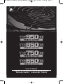
Congratulations on the purchase of your new
Corsair TX650W/TX750W/TX850W/TX950W Power Supply!
T
his User Agreement (the “Agreement”) is a legal agreement between you (“You”), and Corsair
Memory. You are agreeing to be bound by the terms of this agreement, as defined below, by
using the Corsair TX650W/TX750W/TX850W/TX950W power supply (“Product”). If you
h
ave any questions or concerns about the terms of this agreement, please contact us at
http://www.corsairmemory.com. If, prior to using the Product, you decide you are unwilling to
agree to the terms of this agreement, promptly return the Product and the accompanying
i
tems (including written materials and binders or other containers) to Corsair Memory or the
C
orsair Memory authorized distributor from whom you obtained the Product and
accompanying items. If you have already paid for the Product, provide us with your proof of
purchase and we will refund the fees you have paid for these items to you.
Limited Warranty and Limitation of Liability
The Product is guaranteed for sixty (60) months from the date of delivery to the end-user
against defects in materials or workmanship. During this period, the Product will be repaired or
have parts replaced, at our discretion, provided that: (I) the Product is returned to the agent
from whom it was purchased with shipping prepaid; (II) the Product has been purchased by
the end-user and not used for hire purposes; (III) the Product has not been misused, handled
carelessly, or other than in accordance with any instructions provided with respect to its use;
(IV) the Product has not been damaged due to acts of nature, such as lighting, fire, flood, or
earthquake; (V) the warranty stickers have not been removed or tampered with.
Corsair Memory’s warranty on the Product is to the first end user or consumer only, in
accordance with the Corsair Memory’s Limited Warranty. All warranties, express or implied,
including without limitation the implied warranties of merchantability and fitness for a
particular purpose, shall be limited to the duration of the guarantee above. The repair,
replacement, or refund as provided under this express limited warranty is the exclusive
remedy of the consumer, and is provided in lieu of all other warranties, express or implied.
In no event shall Corsair Memory be liable, whether in contract or tort (including negligence)
for damages in excess of the purchase price of the product, or accessory, or for any indirect,
incidental, special or consequential damages of any kind, or loss of revenue or profits, loss of
business, loss of information or data, software or applications or other financial loss arising
out of or in connection with the ability or inability to use the products or accessories to the
full extent these damages may be disclaimed by law.
Corsair Memory’s total liability, whether for breach of contract, warranty, tort (including
negligence), indemnification or otherwise, is limited to the price of the Product sold under
these terms with respect to which losses or damages are claimed. In no event will Corsair
Memory be liable for any loss of use, loss of time, inconvenience, commercial loss, lost profits
or savings or other indirect, incidental, special or consequential damages to the full extent
that may be disclaimed by law. The limitations, exclusions and disclaimers in these terms shall
survive a fundamental breach or breach or the failure of the essential purpose of these terms
or of any remedy contained herein. No action will be brought for any breach of these terms
more than one year after the accrual of such cause of action. For the purpose of this
paragraph, “Corsair Memory” includes its affiliates and its and their respective directors,
officers, employees and agents, each of whom shall be considered as a trust beneficiary.
3
P49-00010 TX Manual.qxd:P49-00010 TX Manual.qxd 8/5/09 5:20 PM Page 3
Seite wird geladen ...
Seite wird geladen ...

6
Installation
Before proceeding with installation, please read this manual in its entirety.
Step A: Replacing your existing power supply
If you are building a new system, skip to Step B.
1
. Disconnect the AC power cord from your wall outlet or UPS and from the existing
power supply.
2. Disconnect all the power cables from your video card, motherboard and all other peripherals.
3
. Follow the direction in your chassis manual and uninstall your existing power supply.
4
. Proceed to Step B.
Step B
1. Make sure the power supply’s AC power cable is not connected.
2. Follow the directions in your chassis manual and install the power supply with the
screws provided.
3. The main 24-pin power cable attached to the power supply has a detachable 4-pin
mechanism in order to support either a 24-pin or a 20-pin socket on the motherboard.
a. If your motherboard has a 24-pin socket, you may connect the 24-pin main power cable
from the TX Series directly to your motherboard.
b. If your motherboard has a 20-pin socket, you must detach the 4-pin cable from the
24-pin connector, and then plug the 20-pin cable onto your motherboard without
connecting the 4-pin connector.
4. The TX Series has an 8-pin +12V; also know as “EPS12V” cable.
a. If your motherboard has an eight-pin +12V socket, connect the eight-pin cable directly
to your motherboard.
b. If your motherboard has a four-pin socket, detach the four-pin from the eight-pin cable,
and then plug the correct 4-pin directly to your motherboard.
WARNING: The detachable 4-pin from the 24-pin main connector is not a “P4” or “+12V”
connector. Serious damage can be caused if you use it in place of a “P4” or “+12V” connector.
5. The TX Series includes two peripheral cables, four PCI-Express cables (two on the TX650W),
and two SATA cables.
a. Connect the peripherals cables to your hard drive and CD-ROM/DVD-ROM
power sockets.
b. Connect the SATA cables to your SATA hard drive’s power sockets.
c. Connect the PCI-Express cables to the power sockets of your PCI-Express video cards
if required
d. Connect the peripheral cables to any peripherals requiring a small 4-pin connector.
e. Make sure all the cables are tightly connected.
6. Connect the AC power cord to the TX Series and turn it on by pushing the switch to
the “I” position.
Congratulations! You have completed installation of your new TX Series power supply and your
system is ready to go!
P49-00010 TX Manual.qxd:P49-00010 TX Manual.qxd 8/5/09 5:20 PM Page 6
Seite wird geladen ...
Seite wird geladen ...
Seite wird geladen ...
Seite wird geladen ...

Installation
Avant de procéder à l'installation, veuillez prendre connaissance du manuel dans son intégralité.
Étape A : Remplacement de l'alimentation existante
Si vous mettez sur pied un nouveau système, passez à l'étape B.
1
. Débranchez le cordon CA de la prise murale, ou de l'alimentation ininterruptible, et de
l'alimentation existante.
2. Débranchez tous les câbles d'alimentation de la carte vidéo, carte mère et autres
p
ériphériques.
3
. Suivez les consignes figurant dans le manuel du châssis et désinstallez l'alimentation existante.
4. Passez à l'étape B.
Étape B
1. Veillez à ce que le câble CA de l'alimentation ne soit pas connecté.
2. Suivez les consignes figurant dans le manuel du châssis et installez l'alimentation au moyen
des vis fournies.
3. Le câble principal à 24 broches connecté à l'alimentation dispose d'un mécanisme amovible
à 4 broches de sorte à pouvoir s'adapter soit à la prise 24 broches, soit à la prise 20 broches
de la carte mère.
a. Si la carte mère dispose d'une prise 24 broches, vous serez en mesure de connecter
directement le câble principal de la série TX.
b. Si la carte mère dispose d'une prise 20 broches, vous devez tout d'abord détacher le
câble à 4 broches du connecteur puis branchez le câble qui n'est désormais muni que
de 20 broches sur la carte mère.
4. La série TX dispose également d'un câble +12V à 8 broches, appelé câble « EPS12V ».
a. Si la carte mère est équipée d'une telle prise, branchez-y directement le câble EPS12V.
b. Si la carte mère dispose d'une prise à 4 broches, détachez les quatre broches du
câble EPS12V puis branchez les quatre broches correspondantes sur la carte mère.
AVERTISSEMENT : Les 4 broches amovibles du connecteur principal à 24 broches ne peuvent
pas tenir lieu de connecteur « P4 » ou « 12V ». Leur utilisation à la place d'un connecteur « P4
» ou « 12V » pourrait entraîner de graves dommages.
5. La série TX comprend deux câbles périphériques, quatre câbles PCI-Express (deux sur le
TX650W) et deux câbles SATA.
a. Branchez les câbles périphériques dans les prises électriques du disque dur et du
CDROM/DVD-ROM.
b. Branchez les câbles SATA dans les prises électriques du disque dur SATA.
c. Branchez les câbles PCI-Express dans les prises électriques des cartes vidéo PCIExpress,
s'il y a lieu.
d. Branchez les câbles périphériques dans les périphériques nécessitant un petit
connecteur à 4 broches.
e. Veillez à ce que tous les câbles soient bien connectés.
6. Branchez le cordon d'alimentation CA à la série TX et allumez en positionnant l'interrupteur
sur position « I ».
Félicitations ! Vous avez terminé l'installation de votre nouvelle alimentation de série TX. Votre
système est prêt !
11
P49-00010 TX Manual.qxd:P49-00010 TX Manual.qxd 8/5/09 5:20 PM Page 11
Seite wird geladen ...

Herzlichen Glückwunsch zum Kauf Ihres neuen
Corsair TX650W/TX750W/TX850W/TX950W Netzteils!
Die vorliegende Benutzervereinbarung (im Folgenden die “Vereinbarung”) ist eine rechtsgültige
V
ereinbarung zwischen Ihnen („Sie“) und Corsair Memory. Durch Ihre Nutzung des Corsair
TX650W/TX750W/TX850W Netzteils (“Produkt”) verpflichten Sie sich zur Einhaltung der im
F
olgenden aufgeführten Bedingungen dieser Vereinbarung. Bei Fragen oder Anliegen
bezüglich dieser Vereinbarung wenden Sie sich bitte unter http://www.corsairmemory.com an
uns. Sollten Sie sich vor Nutzung des Produkts nicht zur Einhaltung dieser
V
ereinbarungsbedingungen bereit erklären, müssen Sie das Produkt und die dazu gehörigen
Komponenten (einschließlich des schriftlichen Materials und aller Beigaben) an Corsair
M
emory oder den Corsair Memory Vertragshändler zurückgeben, von dem Sie das Produkt
und dazu gehörige Komponenten erworben haben. Wenn Sie bereits für das Produkt bezahlt
h
aben, legen Sie Ihren Kaufbeleg bei, damit wir Ihnen den Kaufpreis zurück erstatten können.
Beschränkte Garantie und Haftungsausschluss
Corsair Memory garantiert für sechzig (60) Monate nach dem Lieferdatum an den Endbenutzer,
dass das Produkt frei von Material- und Herstellungsfehlern ist. Während dieser Garantiezeit
ersetzt Corsair Memory das Produkt bzw. defekte Teile nach eigenem Ermessen, vorausgesetzt
dass: (I) das Produkt mit Übernahme der Versandkosten vom Endbenutzer an den Verkäufer
(Corsair Memory oder Fachhändler) zurück gesendet wird; (II) das Produkt vom Endbenutzer
gekauft und nicht für Vermietungszwecke verwendet worden ist; (III) das Produkt entsprechend
der Gebrauchsanweisung verwendet und nicht unsachgemäß behandelt oder missbraucht
worden ist; (IV) das Produkt nicht durch höhere Gewalt wie Blitzschlag, Feuer,
Überschwemmung oder Erdbeben beschädigt worden ist; (V) die Garantieaufkleber nicht
entfernt oder manipuliert worden sind.
Corsair Memorys Garantie auf das Produkt gilt entsprechend der beschränkten Garantie von
Corsair Memory nur für den Erstkäufer. Alle ausdrücklichen und stillschweigenden Garantien,
insbesondere die der Marktgängigkeit und Eignung für einen bestimmten Zweck, sind auf die
Gültigkeitsdauer dieser Garantie beschränkt. Die Reparatur, der Austausch bzw. die
Rückerstattung des Kaufpreises, die im Rahmen dieser ausdrücklichen beschränkten Garantie
angeboten werden, stellen das einzige Rechtsmittel des Käufers dar und treten an Stelle aller
anderen ausdrücklichen oder stillschweigenden Garantien. Corsair Memory lehnt im gesetzlich
zulässigen Umfang jegliche Haftung – gleich aus welchem Rechtsgrund – für Schäden, die
über den Kaufpreis des Produkts bzw. Zubehörteils hinausgehen, oder andere indirekte,
beiläufig entstandene, konkrete oder nachfolgende Schäden jeder Art oder für Einnahme-
oder Gewinneinbußen, Geschäftsverluste, Informations- oder Datenverluste, Verlust von
Software oder Anwendungen oder anderen finanziellen Schäden ab, die aus der Nutzung oder
Unbrauchbarkeit des Produkts bzw. Zubehörteils hervorgehen oder damit in Verbindung
stehen.
Corsair Memorys Gesamthaftung – gleich aus welchem Rechtsgrund – bezüglich der
betroffenen Verluste oder Schäden ist unter diesen Bedingungen auf den Kaufpreis des
Produkts beschränkt. Corsair Memory lehnt im gesetzlich zulässigen Umfang jegliche Haftung
für eingeschränkte Brauchbarkeit, Zeitaufwand, Unannehmlichkeiten, gewerbliche Einbußen,
Gewinn- oder Einsparungseinbußen oder konkrete, indirekte, beiläufig entstandene oder
nachfolgende Schäden ab. Die in diesen Bedingungen definierten Haftungsausschlüsse
bestehen auch im Falle eines wesentlichen Verstoßes gegen diese Bedingungen, einem
Versagen des wesentlichen Zwecks dieser Bedingungen oder eines der darin festgelegten
Rechtsmittel fort. Aufgrund eines Verstoßes gegen diese Bedingungen dürfen nach Ablauf
eines Jahres nach einem derartigen Verstoß keinerlei rechtliche Schritte ergriffen werden. Für
die Auslegung dieses Absatzes umfasst “Corsair Memory” das Unternehmen und verbundene
Unternehmen sowie deren Direktoren, Führungskräfte, Mitarbeiter und Vertreter, die alle als
Begünstigte des Treuhandvermögens gelten.
13
P49-00010 TX Manual.qxd:P49-00010 TX Manual.qxd 8/5/09 5:20 PM Page 13

Einführung
H
erzlichen Glückwunsch zum Kauf Ihres Corsair TX-Netzteils. Die leistungsstarken Netzteile der
TX Reihe nutzen die neuesten Technologien und Komponenten und sind so gebaut, dass sie
viele Jahre zuverlässigen und problemlosen Betrieb liefern. Jedes Corsair TX-Netzteil ist durch
e
ine in der Branche unübertroffene fünfjährige Garantie und einen rund um die Uhr
b
ereitstehenden Kundendienst geschützt.
Vorteile von Corsair
D
ie Corsair TX Reihe basiert auf den neuesten Technologien und modernsten Funktionen:
• Unterstützung für den neuesten ATX12V-Standard (v2.2), abwärtskompatibel mit ATX12V-
Systemen der Version 2.01.
•
Ein extrem leiser, doppelt kugelgelagerter 120-mm-Lüfter (140 mm bei TX750W, TX850W
und TX950W) sorgt für hervorragende Luftströmung bei gleichzeitig außergewöhnlich
geringer Geräuschentwicklung; Die Lüftergeschwindigkeit passt sich der Temperatur an.
• 80% Effizienz bei 20-, 50- und 100-prozentiger Last sorgt für weniger Hitzeentwicklung
und niedrigere Stromrechnungen.
• 99% aktive Leistungsfaktorkorrektur sorgt für saubere und zuverlässige Spannungen.
• Der Universaleingang (AV, 90~264 V) stellt automatisch die richtige Spannung ein. Ein
leidiges Umschalten per Schalter entfällt.
• Die einzelne dedizierte +12-V-Stromschiene ermöglicht größtmögliche Kompatibilität mit
den neuesten Komponenten.
• Schutz vor Überstrom/Überspannung/Stromunterbrechung, Unterspannung- und
Kurzschlussschutz gewährleisten maximale Sicherheit für Ihre wichtigen
Systemkomponenten.
• Hochwertige japanische Kondensatoren bieten kompromisslose Leistung und
Zuverlässigkeit.
• Extra lange, durch Kabeltüllen geschützte Kabel, auch für Tower-Gehäuse geeignet.
• TX650W – Abmessungen:
150 mm (B) x 86 mm (H) x 150 mm (T)
• TX750W/TX850W/TX950W – Abmessungen:
150 mm (B) x 86 mm (H) x 160mm (T)
• Durchschnittliche Lebensdauer: 100.000 Stunden
• 5-jährige Garantie und lebenslanger technischer Support und Kundendienst
14
P49-00010 TX Manual.qxd:P49-00010 TX Manual.qxd 8/5/09 5:20 PM Page 14

Lieferumfang
• Corsair Netzteil TX650W/TX750W/TX850W/TX950W
• Benutzerhandbuch
• AC-Netzkabel
• Kabelbinder
• Befestigungsschrauben
• Corsair Case Badge (Sticker)
Corsair Kabelkonfiguration
• ATX-Netzkabel: 1 x 610 mm (24”), 8Pins
Hinweis: Der ATX-Netzanschluss verfügt über einen abnehmbaren 4-Pin-Mechanismus,
sodass sowohl Motherboard-Sockel mit 24 Pins als auch mit 20 Pins unterstützt werden.
• EPS 12-V-CPU-Kabel: 1 x 610 mm (24”), 8Pins
Hinweis: Der EPS 12-V-Netzanschluss verfügt über einen abnehmbaren
4-Pin-Mechanismus, sodass sowohl Motherboard-Sockel mit 8 Pins als auch mit 4 Pins
(P4/12V) unterstützt werden.
• 4-Pin-Netzkabel:
TX650/750/850W: 2 x 102 mm (4”), 4 Pins (am Ende des Peripheriekabels)
TX950W: 2 x 102 mm (4”), 4-Pin-Adapterkabel
15
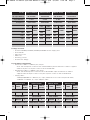
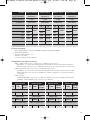
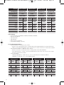
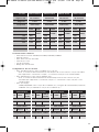
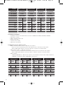
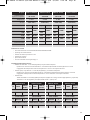
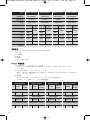
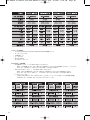
M
odell
A
C-Eingang
Eingangsstrom
Frequenz
DC-Ausgangsnennspannung
+3,3V
+
5V
+
12V
-12V
+5VSB
Gesamtleistung
C
MPSU-650TX
9
0-264V AC
5~12A
47Hz~63Hz
M
aximale
B
elastung
24A
3
0A
5
2A
0,8A
3A
M
aximale
A
usgangsleistung
M
aximale
B
elastung
M
aximale
A
usgangsleistung
M
aximale
B
elastung
M
aximale
A
usgangsleistung
M
aximale
B
elastung
M
aximale
A
usgangsleistung
6
24W
9,6W
15W
650W
170W
C
MPSU-750TX
9
0-264V AC
5~12A
47Hz~63Hz
30A
2
8A
6
0A
0,8A
3A
7
20W
9,6W
15W
750W
180W
C
MPSU-850TX
9
0-264V AC
5~12A
47Hz~63Hz
30A
3
0A
7
0A
0,8A
3A
8
40W
9,6W
15W
850W
180W
C
MPSU-950TX
9
0-264V AC
5~12A
47Hz~63Hz
25A
2
5A
7
8A
0,8A
3A
9
36W
9,6W
15W
950W
150W
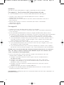
QTY
CMPSU-650TX
LENGTH
CONNECTOR
PER CABLE
PCI-E CABLE
2 610mm 1
SATA CABLE
2 864mm 4
PERIPHERAL CABLE
2 1016mm 5
QTY
CMPSU-750TX
LENGTH
CONNECTOR
PER CABLE
PCI-E CABLE
4 610mm 1
SATA CABLE
2 864mm 4
PERIPHERAL CABLE
2 1016mm 5
QTY
CMPSU-850TX
LENGTH
CONNECTOR
PER CABLE
PCI-E CABLE
4 610mm 1
SATA CABLE
2 864mm 4
PERIPHERAL CABLE
2 1016mm 5
QTY
CMPSU-950TX
LENGTH
CONNECTOR
PER CABLE
PCI-E CABLE
6 610mm 1
SATA CABLE
3 864mm 4
PERIPHERAL CABLE
2 864mm 4
P49-00010 TX Manual.qxd:P49-00010 TX Manual.qxd 8/5/09 5:20 PM Page 15

Installation
Vor Beginn der Installation sollten Sie diese Anleitung vollständig durchlesen.
Schritt A: Austauschen eines vorhandenen Netzteils
Wenn Sie ein neues System bauen, fahren Sie mit Schritt B fort.
1
. Trennen Sie das Netzkabel von der Wandsteckdose oder der USV und dem
vorhandenen Netzteil.
2. Trennen Sie alle weiteren Kabel (Grafikkarte, Mainboard und allen anderen Peripheriegeräte).
3
. Befolgen Sie die Anweisungen im Handbuch, um Ihr vorhandenes Netzteil auszubauen.
4
. Fahren Sie mit Schritt B fort.
Schritt B
1. Vergewissern Sie sich, dass das Netzkabel des Netzteils nicht am Stromnetz angeschlossen ist.
2. Befolgen Sie die Anweisungen Ihres Handbuches, um das Netzteil mit den mitgelieferten
Schrauben zu installieren.
3. Das am Netzteil befestigte 24-Pin-Hauptstromkabel verfügt über einen abnehmbaren
4-Pin-Mechanismus, sodass sowohl Mainboard-Sockel mit 24 Pins als auch mit 20 Pins
unterstützt werden.
a. Wenn Ihr Motherboard einen 24-Pin-Sockel besitzt, können Sie das
24-Pin-Hauptstromkabel der TX Reihe direkt am Motherboard anschließen.
b. Wenn Ihr Motherboard einen 20-Pin-Sockel besitzt, müssen Sie zuerst das 4-Pin-Kabel
vom 24-Pin-Anschluss trennen und dann das 20-Pin-Kabel am Mainboard anschließen;
der 4-Pin-Anschluss wird dabei nicht angeschlossen.
4. Die TX-Reihe besitzt ein 12-V/8-Pin-Kabel, das auch als EPS 12-V-Kabel bezeichnet wird.
a. Wenn Ihr Mainboard einen 8-Pin-Sockel besitzt, können Sie das 8-Pin-Kabel direkt
am Motherboard anschließen.
b. Wenn Ihr Motherboard einen 4-Pin-Sockel besitzt, nehmen Sie das 4-Pin-Kabel vom
8-Pin-Kabel ab und schließen Sie den korrekten 4-Pin-Anschluss direkt am Motherboard an.
WARNUNG: Bei dem vom 24-Pin-Hauptanschluss abnehmbaren 4-Pin-Anschluss handelt es
sich nicht um einen P4- oder 12-V-Anschluss. Wenn Sie diesen Anschluss anstelle eines P4-
oder 12-V-Anschlusses verwenden, kann dies zu schweren Schäden führen!
5. Zur TX-Reihe gehören zwei Peripheriekabel, vier PCI-Express-Kabel (zwei beim TX650W)
sowie zwei SATA-Kabel.
a. Verbinden Sie die Peripheriekabel mit der Festplatte und dem
CD-ROM/DVD-ROM-Laufwerk.
b. Verbinden Sie die SATA-Kabel mit der/den SATA-Festplatte(n).
c. Verbinden Sie ggf. die PCI-Express-Kabel mit der/den PC-Express-Grafikkarte(n).
d. Verbinden Sie die Peripheriekabel mit den Peripheriegeräten, die einen kleinen
4-Pin-Anschluss benötigen.
e. Vergewissern Sie sich, dass alle Kabel fest angeschlossen sind.
6. Verbinden Sie das AC-Netzkabel am TX-Netzteil mit der Steckdose und schalten Sie das
Gerät ein, indem Sie den Schalter in die Position “I” schalten.
Herzlichen Glückwunsch! Sie haben Ihr neues TX-Netzteil installiert und Ihr System
ist jetzt betriebsfähig!
16
P49-00010 TX Manual.qxd:P49-00010 TX Manual.qxd 8/5/09 5:20 PM Page 16

SICHERHEIT UND BEHÖRDLICHE ZULASSUNGEN
CE EN55022:1998/A1:2000/A2:2003 KLASSE B EN 61000-3-2:2000,
E
N 61000-3-3:1995/A1:2001 EN55024:1998/A1:2001/A2:2003
F
CC FCC Teil 15 u. Teil 2 (CISPR 22 KLASSE B)
C-TICK AS/NZS CISPR 22:2002 KLASSE B
UL UL 60950-1
C
SA CSA C22.2 NO. 60950-1
TÜV EN 60950-1
CB IEC 60950-1
W
ARNUNGEN
■ Wegen der Hochspannung im Inneren des Netzteils sollte die Abdeckung des
Netzteils unter keinen Umständen entfernt werden. Das Entfernen der Abdeckung
m
acht die Garantie nichtig.
■ Verwenden Sie das Netzteil ausschließlich in einer sicheren und trockenen Umgebung.
■ Schieben Sie keine Gegenstände in die offenen Lüftungsbereiche oder Lüftergitter
des Netzteils.
■ Bei dem vom 24-Pin-Hauptanschluss abnehmbaren 4-Pin-Anschluss handelt es sich nicht
um einen P4- oder 12-V-Anschluss. Stecken Sie dieses Kabel NICHT mit Gewalt in
den P4- oder ATX 12-V-Sockel auf dem Motherboard.
■ Nicht im Freien verwenden.
17
P49-00010 TX Manual.qxd:P49-00010 TX Manual.qxd 8/5/09 5:20 PM Page 17

Congratulazioni per l’acquisto del nuovo alimentatore
Corsair TX650W/TX750W/TX850W/TX950W!
Q
uesto Contratto con l’utente (“il Contratto”) è un contratto giuridico tra Lei (“Lei”) e Corsair
Memory. Nell’utilizzare l’alimentatore TX650W/TX750W/TX850W/TX950W (“Prodotto”),
accetta di vincolarsi ai termini di questo contratto, come definito sotto. In caso di domande o
d
ubbi relativi alle condizioni stipulate nel presente Contratto, contattarci all’indirizzo
http://www.corsairmemory.com. Se, prima di utilizzare il Prodotto, decide di non accettare le
condizioni del presente Contratto, restituisca immediatamente il Prodotto ed i prodotti
n
onché il relativo materiale di accompagnamento (inclusi i materiali scritti ed i raccoglitori o
a
ltri contenitori) a Corsair Memory o al distributore autorizzato di Corsair Memory dal quale
ha ricevuto il Prodotto ed il relativo materiale di accompagnamento. Se il Prodotto è già stato
pagato, fornire la vostra prova d‘acquisto per ottenere il rimborso di tale pagamento.
Garanzia limitata e limitazione della responsabilità
Il Prodotto è garantito per sessanta (60) mesi a partire dalla data di consegna all’utente finale
per quanto attiene i difetti nei materiali o nell’esecuzione. Durante questo periodo, il Prodotto
verrà riparato o i relativi componenti verranno sostituiti, a discrezione di Corsair Memory, a
condizione che: (i) il Prodotto venga restituito all’agente dal quale è stato acquistato con il
trasporto pagato anticipatamente; (ii) il Prodotto è stato acquistato dall’utente finale e non
utilizzato per scopi di noleggio; (iii) il Prodotto non è stato utilizzato impropriamente,
manipolato con trascuratezza o non conformemente ad alcune istruzioni fornite e relative all’uso;
(iv) il Prodotto non si è danneggiato a causa di eventi naturali, quali fulmini, incendi, inondazioni
o terremoti; (v) gli autoadesivi della garanzia non sono stati rimossi o alterati.
La garanzia di Corsair Memory sul Prodotto è destinata solo al primo utente finale o
consumatore, conformemente alla garanzia limitata di Corsair Memory. Qualsiasi garanzia,
esplicita o implicita, incluse, senza limitazione, eventuali garanzie o condizioni implicite di
commerciabilità o idoneità per uno scopo specifico, saranno limitate alla durata della
garanzia di cui sopra. La riparazione, il rimontaggio o il rimborso previsti da questa garanzia
limitata espressa sono un rimedio esclusivo per il consumatore e vengono forniti al posto di
tutte le altre garanzie, esplicite o implicite. In nessun caso, Corsair Memory potrà essere
ritenuta responsabile, sia ai sensi del contratto o in seguito a dolo (inclusa la negligenza) per
danni il cui importo eccede il prezzo d’acquisto del Prodotto, o degli accessori, o per tutti i
danni indiretti, accidentali, speciali o conseguenti di qualsiasi tipo, o perdita di reddito o
profitti, affari, informazioni o dati, software o applicazioni o altre perdite finanziarie derivanti
o correlate alla possibilità o impossibilità di utilizzare i prodotti nella massima misura in cui
questi danni possono essere risarciti dalla legge.
La responsabilità totale di Corsair Memory, sia per la per la violazione del contratto, della
garanzia, per dolo (inclusa la negligenza), risarcimento o quant’altro, è limitata al Prezzo del
prodotto venduto conformemente a questi termini riguardo ai quali vengono chiesti perdite o
danni. In nessun caso Corsair Memory sarà responsabile per qualsiasi perdita derivante
dall’uso, perdita di tempo, inconvenienti, perdite commerciali, profitti o risparmi persi o altri
danni indiretti, incidentali, speciali o consequenziali nella massima misura prevista dalla
legge. Le limitazioni, le esclusioni e le clausole di esclusione della responsabilità contenute in
queste condizioni resteranno valide anche dopo la violazione o la violazione delle finalità
essenziali di queste condizioni o di qualsiasi rimedio che contengono. Nessun’azione verrà
intentata per qualsiasi violazione di queste condizioni oltre un anno dopo il verificarsi di tale
azione. Per le finalità previste da questo paragrafo, “Corsair Memory“ include le filiali ed i
rispettivi direttori, funzionari, dipendenti ed agenti, ognuno dei quali verrà considerato come
fidecommissario.
18
P49-00010 TX Manual.qxd:P49-00010 TX Manual.qxd 8/5/09 5:20 PM Page 18
Seite wird geladen ...
Seite wird geladen ...

Installazione
Prima di procedere all’installazione, leggere completamente questo manuale.
Passaggio A: Sostituzione dell’alimentatore attuale
Se si sta assemblando un nuovo sistema, andare direttamente al passaggio B.
1
. Staccare il cavo della corrente alternata dalla presa a muro o dall’UPS e
dall’alimentazione esistente.
2. Staccare tutti i cavi elettrici dalla scheda video, dalla scheda madre e da tutte le
a
ltre periferiche.
3
. Attenersi alle istruzioni contenute nel manuale dello chassis e disinstallare
l’alimentazione attuale.
4. Andare al passaggio B.
Passaggio B
1. Verificare che il cavo dell’alimentazione CA non sia collegato.
2. Attenersi alle istruzioni contenute nel manuale dello chassis ed installare l’alimentatore
con le viti fornite.
3. Il cavo principale dell’alimentazione a 24 pin collegato all’alimentatore dispone di un
meccanismo a 4 pin staccabile per supportare il connettore a 24 o 20 pin sulla scheda madre.
a. Se la scheda madre dispone di un connettore a 24 pin, è possibile collegare il cavo
dell’alimentazione principale a 24 pin della serie TX direttamente sulla scheda madre.
b. Se la scheda madre è munita di un connettore a 20 pin, è necessario staccare il cavo a
4 pin dal connettore a 24 pin, e quindi collegare il cavo a 20 pin sulla scheda madre
senza collegare il connettore a 4 pin.
4. La serie TX è munita di un cavo a 8 pin da +12V, noto anche come cavo “EPS12V”
a. Se la scheda madre dispone di un connettore +12V a otto pin, collegare il cavo a otto
pin direttamente sulla scheda madre.
b. Se la scheda madre dispone di un connettore a quattro pin, staccare il cavo a quattro
pin dal cavo a otto pin, quindi collegare il cavo a 4 pin direttamente sulla scheda madre.
AVVISO: Il cavo a 4 pin staccabile dal connettore principale a 24 pin non è un connettore
“P4” o da “+12V”. Se questo connettore viene utilizzato al posto del connettore “P4” o
“+12V”, si potrebbero causare gravi danni.
5. La serie TX include due cavi per periferiche, quattro cavi PCI-Express (due cavi
sull’alimentatore TX650W) e due cavi SATA.
a. Collegare i cavi delle periferiche al disco rigido ed al cavo dell’alimentazione
CD-ROM/DVD-ROM.
b. Collegare i cavi SATA ai connettori dell’alimentazione del disco rigido SATA.
c. Collegare i cavi PCI-Express ai connettori dell’alimentazione delle schede video
PCI-Express video, se necessario.
d. Collegare i cavi delle periferiche a qualsiasi periferica che richiede un piccolo
connettore a 4 pin.
e. Verificare che tutti i cavi siano collegati saldamente.
6. Collegare il cavo dell’alimentazione CA all’alimentatore della serie TX ed accenderlo
portando l’interruttore sulla posizione “I”.
Congratulazioni. L‘installazione del nuovo alimentatore della serie TX è stata completata e si è
pronti per utilizzarlo!
21
P49-00010 TX Manual.qxd:P49-00010 TX Manual.qxd 8/5/09 5:20 PM Page 21
Seite wird geladen ...
Seite wird geladen ...
Seite wird geladen ...
Seite wird geladen ...

Instalación
Antes de continuar con la instalación, lea este manual en su totalidad.
Paso A: Sustitución de la fuente de alimentación existente
Si está configurando un nuevo sistema, vaya al Paso B.
1
. Desconecte el cable de alimentación CA de la toma de corriente de pared o UPS y de la
fuente de alimentación existente.
2. Desconecte todos los cables de alimentación de la tarjeta de vídeo, placa base y otros
p
eriféricos.
3
. Siga las instrucciones del manual de la carcasa y desinstale la fuente de alimentación existente.
4. Siga en el Paso B.
Paso B
1. Asegúrese de que el cable de alimentación CA de la fuente de alimentación no está conectado.
2. Siga las instrucciones del manual de la carcasa e instale la fuente de alimentación con los
tornillos suministrados.
3. El cable de alimentación principal de 24 pines conectado a la fuente de alimentación dispone
de un mecanismo desmontable de 4 pines para admitir conectores de 24 o de 20 pines en la
placa base.
a. Si la placa base tiene un conector de 24 pines, puede conectar el cable de alimentación
principal de 24 pines de la serie TX directamente a la placa base.
b. Si la placa base cuenta con un conector de 20 pines, debe desmontar el cable de
4 pines del conector de 24 pines y, a continuación, conectar el cable de 20 pines a
la placa base sin el cable de 4 pines.
4. La serie TX tiene un cable +12V de 8 pines, también conocido como cable “EPS12V”.
a. Si la placa base dispone de un conector +12V de ocho pines, conecte el cable de
ocho pines directamente a la placa base.
b. Si la placa base dispone de un conector de cuatro pines, desmonte los cuatro pines
del cable de ocho pines y, a continuación, conecte el cable de 4 pines directamente
en la placa base.
ADVERTENCIA: El cable de 4 pines desmontable del conector principal de 24 pines no es un
conector “P4” o “+12V”. Se pueden originar graves daños si se utiliza en lugar de un conector
“P4” o “+12V”.
5. La serie TX incluye dos cables periféricos, cuatro cables PCI-Express (dos en el TX650W)
y dos cables SATA.
a. Conecte los cables periféricos al disco duro y a las tomas de alimentación del
CD-ROM/DVD-ROM.
b. Conecte los cables SATA a las tomas de alimentación del disco duro SATA.
c. Conecte los cables PCI-Express a las tomas de alimentación de las tarjetas de vídeo
PCI-Express, si se precisa.
d. Conecte los cables periféricos a cualquier periférico que requiera un conector
pequeño de 4 pines.
e. Asegúrese de que todos los cables estén firmemente conectados.
6. Conecte el cable de alimentación de CA a la serie TX y enciéndalo pulsando el conmutador
a la posición “I”.
Enhorabuena. Ha finalizado la instalación de su nueva fuente de alimentación de la serie TX
y su sistema está listo para funcionar.
26
P49-00010 TX Manual.qxd:P49-00010 TX Manual.qxd 8/5/09 5:20 PM Page 26
Seite wird geladen ...
Seite wird geladen ...
Seite wird geladen ...
Seite wird geladen ...

Действие А: Замена существующего источника питания
При сборке новой системы перейдите к действию Б.
1
. Отключите шнур питания переменного тока от настенной розетки или источника бесперебойного питания
и от существующего источника питания.
2. Отключите все кабели питания от видеокарты, материнской платы и других периферийных устройств.
3
. Следуя указаниям в руководстве к корпусу, демонтируйте существующий источник питания.
4. Перейдите к действию Б.
Действие Б
1. Убедитесь, что кабель питания переменного тока источника питания не подключен.
2. Следуя указаниям в руководстве к корпусу, установите источник питания с помощью винтов, входящих в
к
омплект поставки.
3. Основной 24-штырьковый кабель питания, подключенный к источнику питания, имеет съемный 4-
штырьковый механизм для обеспечения поддержки 24-штырькового или 20-штырькового сокета на
материнской плате.
а) Если материнская плата имеет 24-штырьковый сокет, можно подключить основной 24-штырьковый
кабель питания напрямую от источника питания TX Series к материнской плате.
б) Если материнская плата имеет 20-штырьковый сокет, необходимо отсоединить 4-штырьковый кабель
от 24-штырькового разъема, а затем подключить 20-штырьковый кабель к материнской плате без
подключения 4-штырькового разъема.
4. Источник питания TX Series имеет 8 штырьков +12 В; также имеется кабель «EPS12V».
а) Если материнская плата имеет 8-штырьковый сокет +12 В, подключите кабель напрямую к материнской
плате.
б) Если материнская плата имеет 4-штырьковый сокет, отсоедините 4 штырька от 8-штырькового кабеля, а
затем подключите соответствующие 4 штырька напрямую к материнской плате.
. 4- , 24- ,
«P4» «+12 ». «P4»
«+12 » .
5. Источник питания TX Series оснащен двумя периферийными кабелями, четырьмя кабелями PCI-Express
(для TX650W — 2 кабеля) и двумя кабелями SATA.
а). Подключите кабели периферийных устройств к жесткому диску и сокетам питания устройств для
чтения компакт-дисков/DVD-дисков.
б). Подключите кабели SATA к сокетам питания жестких дисков SATA.
в). При необходимости подключите кабели PCI-Express к сокетам питания видеокарт PCI-Express
г). Подключите периферийные кабели ко всем периферийным устройствам с малым 4-штырьковым
разъемом.
д). Убедитесь, что все кабели надежно подключены.
6. Подключите шнур питания переменного тока к источнику питания TX Series и включите его с помощью
установки переключателя в положение «I».
Поздравляем Вас! Вы закончили установку нового источника питания TX Series, и Ваша система готова к
работе!
31
P49-00010 TX Manual.qxd:P49-00010 TX Manual.qxd 8/5/09 5:20 PM Page 31
Seite wird geladen ...
Seite wird geladen ...
Seite wird geladen ...
Seite wird geladen ...

安安装装
进行安装之前,请全面阅读本手册。
步骤 A: 更换现有的电源
如果您正在构建一个新的系统,请跳至步骤 B。
1. 从墙壁插座或 UPS 和现有电源中拔出 AC 电源线。
2. 从显卡、主板和所有其他外设中拔出电源线。
3. 遵照机箱手册中的指示卸除现有电源。
4. 继续进行步骤 B。
步骤 B
1. 确保电源的 AC 电源线未连接。
2. 遵照机箱手册中的指示,用附带的螺钉安装电源。
3. 安装在电源上的 24 针主电源线具有可卸除的 4 针结构,以便支持主板上的 24 针或
20 针插座。
a. 如果主板有 24 针插座,您可将 24 针主电源线直接从 TX 系列电源连至主板。
b. 如果主板有 20 针插座,您必须卸除 24 针连接器中的 4 针线缆,然后将
20 针线缆插入主板插座,不连接 4 针连接器。
4. TX 系列电源有一条 8 针 +12V 线缆,即所谓的 “EPS12V” 线缆。
a. 如果您的主板有 8 针 +12V 插座,可将 8 针线缆直接连至主板插座。
b. 如果您的主板有 4 针插座,可从 8 针线缆中卸除 4 个针,然后将正确的
4 针线缆直接插入主板插座。
警警告告:: 从从 2244 针针主主连连接接器器中中卸卸下下的的 44 针针连连接接器器不不是是 ““PP44”” 或或 ““++1122VV”” 连连接接器器。。
如如用用其其替替代代 ““PP44”” 或或 ““++1122VV”” 连连接接器器,,会会造造成成严严重重损损害害。。
5. TX 系列电源有两条外设线缆、四条 PCI-Express 线(TX650W 中为两条)和两条 SATA 线。
a. 将外设线缆连至 CD-ROM/DVD-ROM 电源插座。
b. 将 SATA 线连至 SATA 硬盘电源插座。
c. 视需要将 PCI-Express 线缆连至 PCI-Express 显卡的电源插座。
d. 将外设线缆连至所有需要 4 针小型连接器的外设。
e. 确保所有线缆均已连接稳固。
6. 将 AC 电源线连至 TX 系列电源,将开关推至 “I” 位置,打开电源。
祝祝贺贺!!
您已完成了新的 TX 系列电源的安装,可随时使用系统!
安安规规认认证证
CE EN55022:1998/A1:2000/A2:2003 CLASS B EN 61000-3-2:2000,
EN 61000-3-3:1995/A1:2001 EN55024:1998/A1:2001/A2:2003
FCC FCC 规则第 15 部分和第 2 部分 (CISPR 22 CLASS B)
C-TICK AS/NZS CISPR 22:2002 CLASS B
UL UL 60950-1
CSA CSA C22.2 NO. 60950-1
TUV EN 60950-1
CB IEC 60950-1
警警告告
■
电电源源内内有有高高压压,,任任何何情情况况下下均均不不得得卸卸除除电电源源外外壳壳。。 卸卸除除电电源源罩罩将将使使担担保保失失效效。。
■
请请在在安安全全、、干干燥燥的的适适宜宜环环境境中中使使用用本本电电源源。。
■
切切勿勿将将任任何何物物体体塞塞入入电电源源通通风风口口或或风风扇扇罩罩区区域域。。
■
2244 针针主主电电源源连连接接器器有有可可卸卸式式 44 针针连连接接器器。。 此此 44 针针连连器器并并非非 PP44 或或 AATTXX 1122VV 连连接接器器。。
切切勿勿将将此此线线缆缆强强行行插插入入主主板板上上的的 PP44 或或 AATTXX ++1122VV 插插座座。。
■
仅仅供供室室内内使使用用。。
36
P49-00010 TX Manual.qxd:P49-00010 TX Manual.qxd 8/5/09 5:20 PM Page 36

Corsairの新しい電源ユニット
TX650W/TX750W/TX850W/TX950W
をご購入いただき、ありがとうございます。
このユーザー同意書(以下「本同意書」)は、お客様(以下「お客様」)とCorsairMemory社との間
で
交わされる法的取り決めです。お客様は、CorsairのTX650W/TX750W/TX850W電源ユニット(以
下「本製品」)を使用することにより、本同意書の規約に拘束されることに同意することになります。本同
意書についてご質問や気掛かりな点がある場合は、http://www.corsairmemory.com/company/con
t
acts.aspxから弊社までお問い合わせください。本同意書の規約に同意されない場合は、本製品を使用す
る
前に、Corsair Memory社か本製品および付属品を購入した、Corsair Memory社認定の販売業者店
に本製品および付属品(資料およびバインダーまたはその他の包装箱など)をすみやかに返品してください
。お客様が本製品の代金をすでに支払っている場合は、購入証明書を返品時に添付していただければ、お客
様
に製品の代金を返金いたします。
限定保証および責任の制限
本製品には、エンドユーザーに引き渡された日から60カ月間、材質上および製造上の不良に対する保証が付
きます。当該期間中、本製品は弊社の判断で、修理または部品交換されます。ただし、以下の条件に当ては
まる場合に限ります。(I)本製品が購入者から代理店に元払いで返品されること。(II)本製品がエンドユー
ザーにより購入され、賃貸目的で使用されていないこと。(III)本製品が誤使用されておらず、不注意に扱
われたり、その使用に関して規定されている指示に従わずに扱われていないこと。(IV)本製品が雷、火災、
洪水、または地震などの自然災害により損害を受けていないこと。(V)保証のステッカーが剥がされたり、
改ざんされたりしていないこと。
CorsairMemory社の本製品についての保証は、CorsairMemory社の限定保証に従い、最初のエンドユー
ザーまたはコンシューマのみに適用されます。すべての保証は、明示または黙示にかかわらず、商品性およ
び特定目的への適合性という黙示的な保証も含め、またこれに限らず、上記の保証期間に限定されます。こ
の明示的な限定保証で提供される修理、交換または返金は、コンシューマの唯一の救済手段であり、他の明
示または黙示の保証すべてに代わるものとします。いかなる場合も、Corsair Memory社は、契約の
記述または不法行為(過失を含む)のあるなしを問わず、製品、または付属品の販売価格を超える損害に責
任を持たず、また、製品または付属品の使用の可/不可から生じたか、それらに関連して生じた、あらゆる
種類の間接的、付随的、特別な、結果的な損害、または、収益や利益の損失、取引上の損失、情報やデータ
の紛失、ソフトウェアやアプリケーションもしくはその他の財務上の損失に対して、当該損害が法律により
免責されている限り、責任を持ちません。
損失または損害の主張に関して、契約違反、保証、不法行為(過失を含む)、補償その他に対するCorsair
Memory社の全責任は、これらの規約に基づき販売されている製品の価格に制限されます。いかなる場合
も、Corsair Memory社は、使用不可、時間の損失、不都合、商業的損失、利益もしくは貯蓄の損失、
または、その他の間接的、付随的、特別な、結果的な損害に関し、当該損害が法律により免責されている限
り、責任を持ちません。これらの規約における制限、免責および責任の否認は、根本的違反またはこれらの
規約もしくは本同意書に記載された救済手段の基本目的の違反または不履行後も継続するものとします。こ
れらの規約のいかなる違反に対しても、原因の発生から1年以上経過した場合は訴訟は提起できません。本
項で使用されている「Corsair Memory社」には、その関連会社ならびにその取締役、役員、従業員およ
び代理店が含まれ、それぞれが信託受益者とみなされるものとします。
37
P49-00010 TX Manual.qxd:P49-00010 TX Manual.qxd 8/5/09 5:20 PM Page 37
Seite wird geladen ...
Seite wird geladen ...
Seite wird geladen ...

Corsair
46221 Landing Parkway • Fremont • CA 94538 • USA
Tel: 510 657 8747 • Fax: 510 657 8748
Technical Support/Technischer Support/Support Technique/Assistenza Tecnica/Soporte Técnico
USA and Canada
Tel: 1 800 205 7657
International
Tel: +1 510 657 8747 • Fax: +1 510 657 8748
Forum: www.askthepowerguy.com
Email: powerguy@corsair.com
Web: www.corsair.com
Document Number: P49-00010
©2009 Corsair. The Corsair logo, TX650W Power Supply, TX750W Power Supply, TX850W Power Supply and TX950W Power Supply are
trademarks of Corsair. All other names and products are trademarks and property of their respective owners. Printed in China.
P49-00010 TX Manual.qxd:P49-00010 TX Manual.qxd 8/5/09 5:20 PM Page 1
-
 1
1
-
 2
2
-
 3
3
-
 4
4
-
 5
5
-
 6
6
-
 7
7
-
 8
8
-
 9
9
-
 10
10
-
 11
11
-
 12
12
-
 13
13
-
 14
14
-
 15
15
-
 16
16
-
 17
17
-
 18
18
-
 19
19
-
 20
20
-
 21
21
-
 22
22
-
 23
23
-
 24
24
-
 25
25
-
 26
26
-
 27
27
-
 28
28
-
 29
29
-
 30
30
-
 31
31
-
 32
32
-
 33
33
-
 34
34
-
 35
35
-
 36
36
-
 37
37
-
 38
38
-
 39
39
-
 40
40
-
 41
41
-
 42
42


Corsair ENTHUSIAST TX650W Bedienungsanleitung
- Kategorie
- Netzteile
- Typ
- Bedienungsanleitung
in anderen Sprachen
- English: Corsair ENTHUSIAST TX650W Owner's manual
- français: Corsair ENTHUSIAST TX650W Le manuel du propriétaire
- español: Corsair ENTHUSIAST TX650W El manual del propietario
- italiano: Corsair ENTHUSIAST TX650W Manuale del proprietario
- русский: Corsair ENTHUSIAST TX650W Инструкция по применению
- 日本語: Corsair ENTHUSIAST TX650W 取扱説明書
Verwandte Artikel
-
Corsair CMPSU-450VX Benutzerhandbuch
-
Corsair TX950W Benutzerhandbuch
-
Corsair CMPSU-750TX Benutzerhandbuch
-
-
Corsair ENTHUSIAST TX850 Bedienungsanleitung
-
-
Corsair HX1050W 80PLUS GOLD Bedienungsanleitung
-
-
-
Corsair Marine HX1000W, UK Benutzerhandbuch
