SICK WL24-2Exi Photoelectric Reflex Sensor Bedienungsanleitung
- Kategorie
- Spielzeuge
- Typ
- Bedienungsanleitung

ENGLISH
Photoelectric Reex Sensor
with polarisation lter
Operating instructions
Safety notes
> Marking:
II 2G Ex ia op is IIC T4 Gb.
> It corresponds to the intrinsic safety according to
EN 60079-0 (2012), EN 60079-11 (2012), EN 60079-28 (2007) and
EN 60947-5-6 (2000) (switching output: NAMUR). The intrinsic safety
is only ensured in combination with the corresponding and appropriate
consumable materials and in accordance with the Proof of Intrinsic
Safety. The data and notes of the EC-Declaration of conformity and
national installation directions should be observed.
> Read the operating instructions before starting operation.
> Connection, assembly, and settings only by competent technicians.
> Protect the device against moisture and soiling when operating.
> No safety component in accordance with EU machine guidelines.
Correct use
Directive relevant conformity explosion prevention:
Directive 2014 / 34 / EU.
The devices correspond to the category 2 G and can be used in potentially
explosive atmosphere “zone 1” and “zone 2”.
The WL24-2Exi photoelectric reex sensor is an photo electronic sensor and
is used for optical, non-contact detection of objects, animals; and persons.
A reector is required for operation.
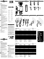
Starting operation
1 Open cover and guard of photoelectric proximity sensor; ensure that
no dirt enters device.
2 With following connectors only:
Equipment plug horizontally (H) and vertically (V) adjustable.
Connect and secure cable receptacle tension-free.
The following apply for connection in B: brn = brown, blu = blue.
Only for versions with terminal chamber:
Disconnect M16 screw xing, remove sealing plugs. Cable outlet can
be swivelled horizontally (H) and vertically (V). Feed tension-free sup-
ply cable through and connect photoelectric proximity sensor as per
connection diagram B and tighten again the M16 screw xing together
with the sealing gasket to ensure the protection class “IP”
of the device.
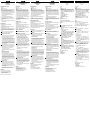
3
Mount suitable reector opposite photoelectric sensor and align roughly.
Adjust for scanning range (see technical data at end of these operating
instructions and see diagram; x = scanning range, y = operating reserve,
y
b
= scanning range, y
g
= limiting scanning distance).
Connect sensor to operating voltage (see type label).
Adjustment of light reception:
Set switch to max.
Determine on / o points of signal strength indicator by swivelling
photoelectric sensor horizontally and vertically. Select middle position
so that red sender beam hits center of reector. With optimum light
reception, signal strength indicator lights up. If it does not light up or if
it is ashing, not enough light is being received: readjust and / or clean
photoelectric sensor and reector.
4 Object detection check:
Move object into the beam; the strength indicator should switch o.
If it does not switch o or continues to blink, reduce the sensitivity
using the switch until it switches o. It should switch on again after the
object is removed. If it does not switch on again, adjust the sensitivity
until the switching threshold is set correctly.
Check sealing faces, seals, and screwed joints, then replace and screw
down cover.
Maintenance
SICK photoelectric sensors are maintenance-free.
We recommend doing the following regularly
- clean the external lens surfaces.
- check the screw connections and plug-in connections.
No modications may be made to devices.
DEUTSCH
Reexions-Lichtschranke
mit Polarisationslter
Betriebsanleitung
Sicherheitshinweise
> Kennzeichnung:
II 2G Ex ia op is IIC T4 Gb.
> Entspricht der Schutzart Eigensicherheit nach EN 60079-0 (2012),
EN 60079-11 (2012), EN 60079-28 (2007) und EN 60947-5-6 (2000)
(Schaltausgang NAMUR). Die Eigensicher heit ist nur in Zusammen-
schaltung mit einem entsprechend zugehörigen Betriebsmittel und
gemäß dem Nachweis der Eigensicherheit gewährleistet. Die in der
EG-Baumusterprüfbescheinigung enthaltenen Daten und Hinweise und
die nationalen Errichterbestimmungen sind zu beachten.
> Vor der Inbetriebnahme die Betriebsanleitung lesen.
> Anschluss, Montage und Einstellung nur durch Fachpersonal.
> Gerät bei Inbetriebnahme vor Feuchte und Verunreinigung schützen.
> Kein Sicherheitsbauteil gemäß EU-Maschinenrichtlinie.
Bestimmungsgemäße Verwendung
Richtlinienkonformität Explosionsschutz: Richtlinie 2014 / 34 / EU.
Die Geräte entsprechen der Kategorie 2 G und können in den explosions-
gefährdeten Bereichen „Zone 1“ und „Zone 2“ eingesetzt werden.
Der Reexions-Lichtschranke WL24-2Exi ist ein photoelektron ischer Sensor
und wird zum optischen, berührungslosen Erfassen von Sachen, Tieren und
Personen eingesetzt.
Inbetriebnahme
1 Deckel und Schutzhaube des Lichttasters önen; darauf achten, dass
kein Schmutz in das Gerät gelangt.
2 Nur bei den Steckerversionen:
Gerätestecker nach horizontal (H) und vertikal (V) schwenkbar.
Leitungsdose spannungsfrei aufstecken und festschrauben.
Für Anschluss in B gilt: brn = braun, blu = blau.
Nur bei Versionen mit Klemmenanschlussraum:
M16-Verschraubung lösen, Dichtungsstopfen entfernen. Leitungsau-
stritt nach horizontal (H) und vertikal (V) schwenkbar. Spannungsfreie
Versorgungsleitung durchführen und Lichtschranke nach Anschlusss
-
chema B anschließen und die M16-Verschraubung mit Dichtung wieder
anziehen, damit die IP-Schutzart des Gerätes sichergestellt wird.
WL24-2Exi
-------------------------------------------------------- 8010640.11K6 0419 COMAT -----------------------------------------------------
B WL24-2X230 WL24-2X430 WL24-2X430S07
A WL24-2X230
WL24-2X430
WL24-2X430S07
3 Geeigneten Reektor gegenüber der Lichtschranke montieren und grob
ausrichten. Dabei Reichweite beachten (s. technische Daten am Ende
dieser Betriebsanleitung und s. Diagramm; x = Reichweite,
y = Funktionsreserve, y
b
= Betriebsreichweite, y
g
= Grenzreichweite).
Sensor an Betriebsspannung legen (s. Typenaufdruck).
Justage Lichtempfang:
Drehknopf auf max. stellen.
Ein- / Ausschaltpunkte der Empfangsanzeige durch horizontales und
vertikales Schwenken der Lichtschranke ermitteln. Mittelstellung so
wählen, dass der rote Sendelichtstrahl in der Reektormitte auftrit.
Bei optimalem Lichtempfang leuchtet die Empfangsanzeige perma-
nent. Leuchtet sie nicht oder blinkt sie, wird kein oder zuwenig Licht
empfangen: Lichtschranke und Reektor neu justieren bzw. reinigen.
4 Kontrolle Objekterfassung:
Objekt in den Strahlengang bringen; die Empfangsanzeige muss
erlöschen. Leuchtet sie weiterhin oder blinkt sie, die Empndlichkeit
am Drehknopf so lange reduzieren, bis sie erlischt. Nach Entfernen des
Objektes muss sie wieder aueuchten; ist dies nicht der Fall, Empnd
-
lichkeit so lange verändern, bis die Schaltschwelle korrekt eingestellt ist.
Dichtächen, Dichtungen und Verschraubungen kontrollieren, dann
Deckel aufsetzen und festschrauben.
Wartung
SICK-Lichtschranken sind wartungsfrei.
Wir empfehlen, in regelmäßigen Abständen
– die optischen Grenzächen zu reinigen,
– Verschraubungen und Steckverbindungen zu überprüfen.
Veränderungen an Geräten dürfen nicht vorgenommen werden.
14
(0.55)
37
(1.46)
max. 32
(1.26)
27
(1.06)
10
(0.39)
M5
87.5 (3.44)
4.7
(0.19)
11.8
(0.46)
30 (1.18)
65 (2.56)
1
2
3
4
6
7
14
(0.55)
6.5
(0.26)
14
(0.55)
17.5
(0.69)
5
+8.2
V
0 V
1
2
Ø 5 ... 10 mm
(0.2 ... 0.39)
3
1 2
4
WL24-2Exi II 2G Ex ia op is IIC T4 Gb
-X230
-X430
X430S07
Sensing range max.
(with reflector PL80A)
Schaltabstand max.
(mit Reflektor PL80A)
Distance de commutation max.
(avec réflecteur PL80A)
Distância de comutação max.
(com refletor PL80A)
0 … 22 m
Light spot diameter / distance Lichtfleckdurchmesser
/ Entfernung Diamètre de la tache lumineuse / distance Diâmetro do ponto de luz / distância
250 mm / 15 m
Supply voltage V
S
Versorgungsspannung U
V
Tension d‘alimentation U
V
Tensão de força U
V
DC 8.2 V (Ri ca. 1 kOhm) (5.0 V … 15.5 V)
1) 2)
Switching frequency max. Schaltfolge max. Le signal max. Sequência do sinal max. 50 / s
3)
Response time Ansprechzeit Temps de réponse Tempo de reação ≥ 10 ms
4)
Switching output Schaltausgang Sortie de commutation Saída de comutação EN 60947-5-6 (2000) (NAMUR)
Enclosure rating Schutzart Type de protection Tipo de proteção IP 67
Protection class Schutzklasse Classe de protection Classe de proteção
5)
Circuit protection Schutzschaltungen Circuits de protection Circuitos protetores A, C
6)
Ambient operating temperature T4 Betriebsumgebungstemperatur T4 Température ambiante T4 Temperatura ambiente de operação T4 –20 °C < TA < +60 °C
EU-type examination certificate EG-Baumusterprüfbescheinigung Certificat d’essai d’homologation CE Certificado de exame CE de tipo PTB 03 ATEX 2105 (www.sick.com)
EU-Declaration of Conformity EG-Konformitätserklärung Déclaration de conformité CE Declaração de conformidade da CE www.sick.com
Voltage U
i
Spannung U
i
Tension U
i
Tensão U
i
15.5 V
Current I
i
Strom I
i
Intensité I
i
Corrente I
i
53 mA
Power P
i
Leistung P
i
Puissance P
i
Potência P
i
100 mW
Effective internal capacity C
i
Wirksame innere Kapazität C
i
Capacité interne efficace C
i
Capacidade interna eficaz C
i
80 nF
Effective internal inductivity L
i
Wirksame innere Induktivität L
i
Inductance interne efficace L
i
Indutância interna eficaz L
i
~0 µH
7)
1)
Provided with isolating switching device EN 2 Ex
2)
Limit values:
Ripple max. 0.4 V
pp
3)
With light / dark ratio 1:1
4)
Signal transit time with resistive load
5)
Reference voltage 50 V DC
6)
A = V
S
connections reversepolarity protected
C = Interference pulse suppression
7)
Negligible small
1)
Versorgung mit Trennschaltgerät EN 2 Ex
2)
Grenzwerte:
Restwelligkeit max. 0,4 V
SS
3)
Mit Hell- / Dunkelverhältnis 1:1
4)
Signallaufzeit bei ohmscher Last
5)
Bemessungsspannung DC 50 V
6)
A = U
V
-Anschlüsse verpolsicher
C = Störimpulsunterdrückung
7)
Vernachlässigbar klein
1)
Alimentation avec sectionneur EN 2 Ex
2)
Valeurs limites:
Ondulation résiduelle max. 0,4 V
SS
3)
Pour un rapport clair / sombre 1:1
4)
Durée du signal en charge ohmique
5)
Tension de calcul 50 V c.c.
6)
A = Raccordements U
V
protégés contre
C = Suppression des impulsions parasites
7)
Négligeable
1)
Alimentação com chave interruptora EN 2 Ex
2)
Valores limite:
Ondulação residual max. 0,4 V
SS
3)
Com uma relação luminoso / escuro de 1:1
4)
Tempo de transição do sinal com carga ôhmica
5)
Tensão de dimensionamento DC 50 V
6)
A = Conexões U
V
protegidas contra inversão de polos
C = Supressão de impulsos parasitas
7)
Negligentemente pequeno
WL24-2Exi II 2G Ex ia op is IIC T4 Gb
-X230
-X430
X430S07
Distanza di commutazione max.
(con riflettore PL80A)
Distancia de conmutación max.
(con reflector PL80A)
检测范围, 最大
(带反射器 PL80A)
スイッチ間隔、最大値
「リフレクタ PL80A 付き」
0 … 22 m
Diametro punto luminoso / distanza Diámetro / distancia de mancha de luz
光点直径 / 距离 スポット径 / 距離
250 mm / 15 m
Tensione di alimentazione U
V
Tensión de alimentación U
V
电源电压U
V
供給電圧 U
V
DC 8.2 V (Ri ca. 1 kOhm) (5.0 V … 15.5 V)
1) 2)
Sequenza signali max. Secuencia de señales max.
最小信号序列 max. 最小信号シーケンス max. 50 / s
3)
Tempo di risposta Tiempo de reacción
触发时间 応答時間
≥ 10 ms
4)
Uscita di commutazione Salida de conexión
开关输出端 スイッチング出力
EN 60947-5-6 (2000) (NAMUR)
Tipo di protezione Tipo de protección
保护种类 保護等級
IP 67
Classe di protezione Protección clase
保护级别 保護クラス
5)
Commutazioni di protezione Circuitos de protección
保护电路 保護回路
A, C
6)
Temperatura ambiente circostante T4 Temperatura ambiente de servicio T4 工作环境-温度 T4 使用周囲温度 T4 –20 °C < TA < +60 °C
Attestato di certificazione CEE Certificado de homologación de tipo CE
欧盟型式检验证书 EU 型式検定合格証 PTB 03 ATEX 2105 (www.sick.com)
Dichiarazione di conformità CEE Declaración de conformidad de la CE
欧盟一致性声明
EU 適合宣言書 www.sick.com
Tensione U
i
Tensión U
i
电压 U
i
電圧 U
i
15.5 V
Corrente I
i
Corriente I
i
电流 I
i
電流 I
i
53 mA
Potenza P
i
Potencia P
i
功率 P
i
出力 P
i
100 mW
Capacità interna efficace C
i
Capacidad interna efectiva C
i
内部有效电容 C
i
効果的な内部キャパシタンス C
i
80 nF
Induttività interna efficace L
i
Inductividad interna efectiva L
i
内部有效电感 L
i
効果的な内部インダクタンス L
i
~0 µH
7)
1)
Oggetto 90 %, remissione sec. DIN 5033
2)
Alimentazione con separatore EN 2 Ex
3)
Valori limite:
Ondulazione residua max. 0,4 V
SS
4)
Con relatio chiaro / scuro 1:1
5)
Tempo di continuare de segnale a resistenza ohmica
6)
Tensione di taratura DC 50 V
7)
A = U
V
-collegamenti con protez. contro inversione di
poli
C = Soppressione impulsi di disturbo
1)
Objeto 90 % de remission en base a DIN 5033
2)
Alimentación con seccionador EN 2 Ex
3)
Valores límite:
Ondulación residual max. 0,4 V
SS
4)
Con una relación claro / oscuro de 1:1
5)
Duración de la señal con carga óhmica
6)
Tensión tolerable DC 50 V
7)
A = Conexiones U
V
a prueba de inversión de polaridad
C = Represión de impulso de interferencia
1)
絶縁スイッチング装置 EN 2 Ex 装備
2)
操作电流:
极限值剩余波纹度 max. 0,4 V
SS
3)
亮 / 暗比 1:1
4)
电阻性负载时,传感器检测到变化
时输出信号的转换时间
5)
限定电压DC 50 V
6)
A = U
V
-
接头防反接
C = 消除干扰脉冲
7)
几乎可以忽略
1)
配备有隔离开关装置 EN 2 Ex
2)
限界値:
最大 0,4 V
SS
3)
明暗比率 1:1の場合
4)
抵抗負荷における信号遷移時間
5)
定格電圧 DC 50 V
6)
A = U
V
接続 逆接保護
C = 干渉パルス制御
7)
無視できるほど小さい
4
(0.16)
8
(0.31)
12
(0.47)
16
(0.63)
20
(0.79)
24
(0.94)
100
10
y
b
y
g
PL 80A
PL 20A
PL 30A
PL 40A / PL 50A
% of sensing distance
Distance in mm (inch)
1
1
2
2
+8.2 V
0 V
4
4
NC
brn
wht
3
NC
blu
3
1
1
2
2
+8.2 V
0 V
4
4
NC
brn
wht
3
0 V
blu
3
BZ int48
Please find detailed addresses and further locations in all major industrial
nations at www.sick.com
Australia
Phone +61 (3) 9457 0600
Austria
Phone +43 (0) 2236 62288-0
Belgium/Luxembourg
Phone +32 (0) 2 466 55 66
Brazil
Phone +55 11 3215-4900
Canada
Phone +1 905.771.1444
Czech Republic
Phone +420 2 57 91 18 50
Chile
Phone +56 (2) 2274 7430
China
Phone +86 20 2882 3600
Denmark
Phone +45 45 82 64 00
Finland
Phone +358-9-25 15 800
France
Phone +33 1 64 62 35 00
Germany
Phone +49 (0) 2 11 53 01
Hong Kong
Phone +852 2153 6300
Hungary
Phone +36 1 371 2680
India
Phone +91-22-6119 8900
Israel
Phone +972-4-6881000
Italy
Phone +39 02 27 43 41
Japan
Phone +81 3 5309 2112
Malaysia
Phone +603-8080 7425
Mexico
Phone +52 (472) 748 9451
Netherlands
Phone +31 (0) 30 229 25 44
New Zealand
Phone +64 9 415 0459
Norway
Phone +47 67 81 50 00
Poland
Phone +48 22 539 41 00
Romania
Phone +40 356-17 11 20
Russia
Phone +7 495 283 09 90
Singapore
Phone +65 6744 3732
Slovakia
Phone +421 482 901 201
Slovenia
Phone +386 591 78849
South Africa
Phone +27 (0)11 472 3733
South Korea
Phone +82 2 786 6321
Spain
Phone +34 93 480 31 00
Sweden
Phone +46 10 110 10 00
Switzerland
Phone +41 41 619 29 39
Taiwan
Phone +886-2-2375-6288
Thailand
Phone +66 2 645 0009
Turkey
Phone +90 (216) 528 50 00
United Arab Emirates
Phone +971 (0) 4 88 65 878
United Kingdom
Phone +44 (0)17278 31121
USA
Phone +1 800.325.7425
Vietnam
Phone +65 6744 3732
SICK AG, Erwin-Sick-Strasse 1, D-79183 Waldkirch
More representatives and agencies at www.sick.com ∙ Subject to change
without notice ∙ The specied product features and technical data do not
represent any guarantee.
Weitere Niederlassungen nden Sie unter www.sick.com ∙ Irrtümer
und Änderungen vorbehalten ∙ Angegebene Produkteigenschaften und
technische Daten stellen keine Garantieerklärung dar.
Plus de représentations et d’agences à l’adresse www.sick.com ∙ Sujet à
modication sans préavis ∙ Les caractéristiques de produit et techniques
indiquées ne constituent pas de déclaration de garantie.
Para mais representantes e agências, consulte www.sick.com ∙ Alterações
poderão ser feitas sem prévio aviso ∙ As características do produto e os
dados técnicos apresentados não constituem declaração de garantia.
Altri rappresentanti ed agenzie si trovano su www.sick.com ∙ Contenuti
soggetti a modiche senza preavviso ∙ Le caratteristiche del prodotto e i
dati tecnici non rappresentano una dichiarazione di garanzia.
Más representantes y agencias en www.sick.com ∙ Sujeto a cambio sin
previo aviso ∙ Las características y los datos técnicos especicados no
constituyen ninguna declaración de garantía.
欲了解更多代表机构和代理商信息,请登录 www.sick.com ∙
如有更改, 不另行通知 ∙ 对所给出的产品特性和技术参数
的正确性不予保证。
その他の営業所はwww.sick.com よりご覧ください ・ 予告な
しに変更されることがあります ・ 記載されている製品機能
および技術データは保証を明示するものではありません。
2006/42/EC
NO
SAFETY
Seite wird geladen ...
-
 1
1
-
 2
2


SICK WL24-2Exi Photoelectric Reflex Sensor Bedienungsanleitung
- Kategorie
- Spielzeuge
- Typ
- Bedienungsanleitung
in anderen Sprachen
- English: SICK WL24-2Exi Photoelectric Reflex Sensor Operating instructions
- français: SICK WL24-2Exi Photoelectric Reflex Sensor Mode d'emploi
- español: SICK WL24-2Exi Photoelectric Reflex Sensor Instrucciones de operación
- italiano: SICK WL24-2Exi Photoelectric Reflex Sensor Istruzioni per l'uso
- português: SICK WL24-2Exi Photoelectric Reflex Sensor Instruções de operação
- 日本語: SICK WL24-2Exi Photoelectric Reflex Sensor 取扱説明書
Verwandte Artikel
-
SICK WLL24-2Exi Bedienungsanleitung
-
-
-
-
-
-
-
-
-