Tripp Lite DDR1323S Full Motion Flat Screen Desk Mount Bedienungsanleitung
- Kategorie
- Flachbildschirm-Schreibtischhalterungen
- Typ
- Bedienungsanleitung

1
Owner’s Manual
WARRANTY
REGISTRATION
Register online today for a
chance to win a FREE Tripp Lite
product! www.tripplite.com/warranty
Full Motion
Flat Screen Desk Mount
MODEL: DDR1323S
CAUTION: DO NOT EXCEED MAXIMUM LISTED WEIGHT CAPACITY. SERIOUS INJURY OR
PROPERTY DAMAGE MAY OCCUR!
1111 W. 35th Street, Chicago, IL 60609 USA • www.tripplite.com/support
Copyright © 2013 Tripp Lite. All rights reserved.
75x75
100x100
23”
MAX
9kg
(19.8lbs)
MAX
Español 11 • Français 21 • Русский 31 • Deutsch 41
13-04-174-93329B.indb 1 5/14/2013 1:30:18 PM

2
NOTE: Read the entire instruction manual before you start installation and assembly.
Warranty & Warranty Registration
WARNING
• Do not begin the installation until you have read and understood the instructions
and warnings contained in this manual. If you have any questions regarding any
of the instructions or warnings, please visit www.tripplite.com/support.
• This mounting bracket was designed to be installed and utilized ONLY as
specified in this manual. Improper installation of this product may cause damage
or serious injury.
• Make sure that the supporting surface will safely support the combined load of
the equipment and all attached hardware and components.
• Always use an assistant or mechanical lifting equipment to safely lift and position
equipment.
• Tighten screws rmly, but do not over tighten. Over tightening can damage the
items, greatly reducing their holding power.
• This product is intended for indoor use only. Using this product outdoors could
lead to product failure and personal injury.
5-Year Limited Warrant
Seller warrants this product, if used in accordance with all applicable instructions, to be free from original defects
in material and workmanship for a period of 5 years from the date of initial purchase. If the product should
prove defective in material or workmanship within that period, Seller will repair or replace the product, in its sole
discretion.
THIS WARRANTY DOES NOT APPLY TO NORMAL WEAR OR TO DAMAGE RESULTING FROM ACCIDENT, MISUSE,
ABUSE OR NEGLECT. SELLER MAKES NO EXPRESS WARRANTIES OTHER THAN THE WARRANTY EXPRESSLY
SET FORTH HEREIN. EXCEPT TO THE EXTENT PROHIBITED BY APPLICABLE LAW, ALL IMPLIED WARRANTIES,
INCLUDING ALL WARRANTIES OF MERCHANTABILITY OR FITNESS, ARE LIMITED IN DURATION TO THE WARRANTY
PERIOD SET FORTH ABOVE; AND THIS WARRANTY EXPRESSLY EXCLUDES ALL INCIDENTAL AND CONSEQUENTIAL
DAMAGES. (Some states do not allow limitations on how long an implied warranty lasts, and some states do not
allow the exclusion or limitation of incidental or consequential damages, so the above limitations or exclusions
may not apply to you. This warranty gives you specific legal rights, and you may have other rights which vary from
jurisdiction to jurisdiction).
WARNING: The individual user should take care to determine prior to use whether this device is suitable, adequate
or safe for the use intended. Since individual applications are subject to great variation, the manufacturer makes
no representation or warranty as to the suitability or fitness of these devices for any specific application.
WARRANTY REGISTRATION
Visit www.tripplite.com/warranty today to register the warranty for your new Tripp Lite product. You’ll be
automatically entered into a drawing for a chance to win a FREE Tripp Lite product!*
* No purchase necessary. Void where prohibited. Some restrictions apply. See website for details.
Tripp Lite has a policy of continuous improvement. Specifications are subject to change without notice.
13-04-174-93329B.indb 2 5/14/2013 1:30:18 PM

3
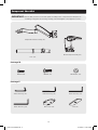
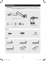
Component Checklist
IMPORTANT: Ensure that you have received all parts according to the component checklist prior to
installing. If any parts are missing or faulty, visit www.tripplite.com/support for service.
Pole (x1)
Desk Clamp Assembly (x1)
M4X14 (x4) M5X14 (x4) D5 Washer (x4)
Package M
Package P
Adapter Bracket Assembly (x1)
3mm Allen Key (x1)
6mm Allen Key (x1)
4mm Allen Key (x1)
Base Plate (x1)
5mm Allen Key (x1)
Pad (x1)
13-04-174-93329B.indb 3 5/14/2013 1:30:18 PM

4
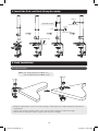
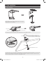
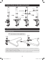
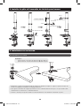
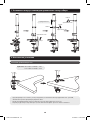
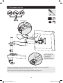
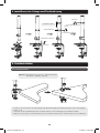
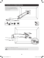
1. Install the Pole and Desk Clamp Assembly
2. Desk Installation
• Determine approximate location for mount, keeping in mind display size, height adjustment and pitch/roll
requirements.
• Slip the desk mount assembly over the edge of desk so that clamp fully contacts desk edge.
• Turn the knob to adjust the clamp to edge of desk and secure it tightly.
Note: min. desktop thickness=10mm (.4”)
max. desktop thickness=90mm (3.5”)
2a. Edge Installation
tighten
loosen
collar
tighten
tighten
3mm Allen Key
3mm Allen Key
3mm Allen Key
adjustable height
13-04-174-93329B.indb 4 5/14/2013 1:30:18 PM

5
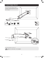
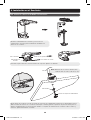
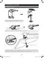
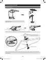
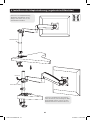
2. Desk Installation
Disassemble the desk clamp assembly and select the right
components for hole installation.
Re-install the base plate with three retained attachment screws. Tighten securely.
From below the desk, insert retained clamp adjustment screw through pad and up through the hole in the desk.
Thread screw by turning the knob into base plate but do not tighten completely at this time. Center the desk
mount assembly over the hole and then securely tighten screw.
Note: min. hole diameter =10mm (.4”)
max. hole diameter =70mm (2.75”)
2b. Hole Installation
Pad
Clamp Adjustment Screw
Base Plate
Rubber Pad
Attachment Screw
4mm Allen Key
13-04-174-93329B.indb 5 5/14/2013 1:30:18 PM

6
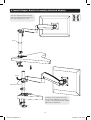
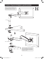
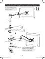
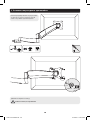
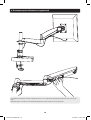
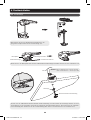
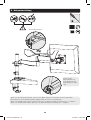
3. Install Adapter Bracket
Pick up and orient the adapter bracket
assembly so that the mounting holes in the
assembly are aligned with the holes in the
back of display.
TV
TV
TV
Screw the VESA plate onto the TV.
Tighten all screws but do not over tighten.
D5 Washer
M4X14
M5X14
13-04-174-93329B.indb 6 5/14/2013 1:30:18 PM

7
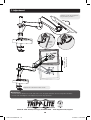
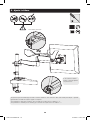
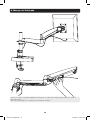
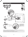
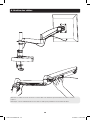
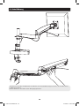
4. Install Adapter Bracket Assembly (attached display)
Slide the adapter bracket assembly
(with the display attached) down the
pole until it touches the collar.
Pulling up on the handle allows the
arm to rotate 360 degrees in either
direction. Releasing the handle enables
tightening or adjustment.
tighten
Collar
Adjustable Handle
13-04-174-93329B.indb 7 5/14/2013 1:30:18 PM

8
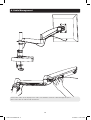
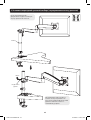
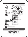
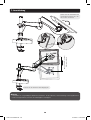
5. Height Adjustment
Please tighten socket
set screw if the joints
make popping sounds
in use.
Please keep the forearm level when adjusting pressure. Use a proper Allen key to slightly loosen or tighten the
adjustment screw as necessary.
If display settles on its own, rotate adjustment screw towards the “+” symbol.
If display rises on its own, rotate adjustment screw towards the “-” symbol.
6mm Allen Key
13-04-174-93329B.indb 8 5/14/2013 1:30:19 PM

9
6. Cable Management
FOLD 3
DUSTCATCHER
Connect the cables to the display. Press cable cover inward to route the cables through the space.
Note: Leave slack in cable for arm movement.
13-04-174-93329B.indb 9 5/14/2013 1:30:19 PM

10
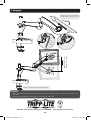
360°
7. Adjustment
Tighten screws by using Allen
key to x the position
Adjust to the desired location or tilt.
+90°
-40°
Max 335mm (13”)
Height Adjustment
Maintenance
• Check that the bracket is secure and safe to use at regular intervals (at least every three months).
• Please visit www.tripplite.com/support if you have any questions.
360°
5mm
Allen
Key
1111 W. 35th Street, Chicago, IL 60609 USA • www.tripplite.com/support
13-04-174-93329B.indb 10 5/14/2013 1:30:20 PM

11
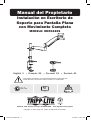
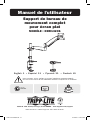
Manual del Propietario
Instalación en Escritorio de
Soporte para Pantalla Plana
con Movimiento Completo
MODELO: DDR1323S
PRECAUCIÓN: NO EXCEDA LA CAPACIDAD MÁXIMA DE CARGA INDICADA.
¡PUEDE OCURRIR UNA LESIÓN SEVERA O DAÑO A LA PROPIEDAD!
1111 W. 35th Street, Chicago, IL 60609 USA • www.tripplite.com/support
Copyright © 2013 Tripp Lite. Todos los derechos reservados.
75 x 75
100 x 100
23”
MÁX
9 kg
(19.8 lbs)
MÁX
English 1 • Français 21 • Русский 31 • Deutsch 41
13-04-174-93329B.indb 11 5/14/2013 1:30:21 PM

12
NOTA: Lea completo el manual de instrucciones antes de iniciar la instalación y ensamble.
Garantía y Registro de Garantía
ADVERTENCIA
• No inicie la instalación hasta que haya leído y entendido las instrucciones y
advertencias contenidas en este manual. Si tiene alguna pregunta con respecto
a alguna de las instrucciones o advertencias, visite por favor www.tripplite.com/
support.
• El soporte de instalación fue diseñado para instalarse y usarse SOLAMENTE
como se especifica en este manual. La instalación incorrecta de este producto
puede causar daños o lesiones severas.
• Cerciórese de que la supercie de apoyo soporte con seguridad la carga
combinada del equipo y los accesorios y componentes agregados.
• Utilice siempre un ayudante o equipo de elevación mecánico para levantar y
colocar el equipo con seguridad.
• Apriete los tornillos rmemente pero no en exceso. Apretar en exceso puede
dañar los artículos, reduciendo grandemente su capacidad de soporte.
• Este producto está diseñado para usarse sólo en interiores. El utilizar este
producto en exteriores podría conducir a fallas del producto y lesiones
personales.
Garantía Limitada por 5 Años
El vendedor garantiza este producto, si se usa de acuerdo con todas las instrucciones aplicables, de que está
libre de defectos en material y mano de obra por un período de 5 años a partir de la fecha de compra inicial. Si
el producto prueba ser defectuoso en material o mano de obra dentro de ese período, el vendedor reparará o
reemplazará el producto a su entera discreción.
ESTA GARANTÍA NO APLICA AL DESGASTE NORMAL O A DAÑOS RESULTANTES DE ACCIDENTES, MAL USO,
ABUSO O NEGLIGENCIA. EL VENDEDOR NO OTORGA GARANTÍAS EXPRESAS DISTINTAS DE LA ESTIPULADA AQUÍ.
EXCEPTO A LA EXTENSIÓN PROHIBIDA POR LA LEY APLICABLE, TODAS LAS GARANTÍAS IMPLÍCITAS, INCLUYENDO
TODAS LAS GARANTÍAS DE COMERCIALIZACIÓN O IDONEIDAD, ESTÁN LIMITADAS EN DURACIÓN AL PERÍODO
DE GARANTÍA ESTABLECIDO; Y ESTA GARANTÍA EXCLUYE EXPRESAMENTE TODOS LOS DAÑOS INCIDENTALES Y
CONSECUENCIALES. (Algunos estados no permiten limitaciones en cuanto dura una garantía y algunos estados
no permiten la exclusión de limitación de daños incidentales o consecuenciales, de modo que las limitaciones
anteriores pueden no aplicar para usted. Esta garantía le otorga derechos legales especícos y usted puede tener
otros derechos que pueden variar de una jurisdicción a otra).
ADVERTENCIA: Antes de usarlo, cada usuario debe debe tener cuidado al determinar si este dispositivo es
adecuado o seguro para el uso previsto. Ya que las aplicaciones individuales están sujetas a gran variación, el
fabricante no garantiza la adecuación de estos dispositivos para alguna aplicación especíca.
Tripp Lite tiene una política de mejora continua. Las especicaciones están sujetas a cambio sin previo aviso.
13-04-174-93329B.indb 12 5/14/2013 1:30:21 PM

13
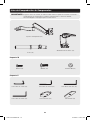
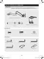
Lista de Comprobación de Componentes
IMPORTANTE:
Asegúrese antes de instalar, de haber recibido todas las partes de acuerdo a la lista de
comprobación de componentes. Si faltase cualquier parte o estuviese dañada,
visite www.tripplite.com/support para solicitar servicio.
Poste (x1)
Abrazadera de Escritorio (x1)
M4X14 (x4) M5X14 (x4) Arandela D5 (x4)
Paquete M
Paquete P
Soporte de Adaptador (x1)
Llave Allen de 3 mm (x1)
Llave Allen de 6 mm (x1)
Llave Allen de 4 mm (x1)
Placa de Base (x1)
Llave Allen de 5 mm (x1)
Almohadilla (x1)
13-04-174-93329B.indb 13 5/14/2013 1:30:21 PM

14
1. Instale el Poste y la Abrazadera de Escritorio
2. Instalación en el Escritorio
• Determine la ubicación aproximada para instalación, teniendo en cuenta los requerimientos de tamaño de
pantalla, ajuste de altura e inclinación/giro.
• Deslice el conjunto de instalación de escritorio sobre el borde del escritorio de modo que la abrazadera haga
contacto completo con el borde del escritorio.
• Gire la perilla para ajustar la abrazadera al borde del escritorio y asegúrela rmemente.
Nota: Espesor mínimo de escritorio=10 mm (0.4”)
Espesor máximo de escritorio=90 mm (3.5”)
Instalación del 2o. Borde
apretar
aflojar
collarín
apretar
apretar
Llave Allen de 3 mm
Llave Allen de 3 mm
Llave Allen de 3 mm
altura ajustable
13-04-174-93329B.indb 14 5/14/2013 1:30:21 PM

15
2. Instalación en el Escritorio
Desarme la abrazadera de escritorio y seleccione los
componentes correctos para la instalación mediante un
orificio en el escritorio.
Reinstale la placa de base con tres tornillos de sujeción. Apriete con rmeza.
Desde abajo del escritorio, inserte el tornillo de sujeción de la abrazadera a través de la almohadilla y hacia
arriba a través del oricio en el escritorio. Enrosque el tornillo girando la perilla en la placa de base pero no
apriete completamente en este momento. Centre el conjunto de instalación en escritorio sobre el orificio y
entonces apriete firmemente el tornillo.
Nota: Diámetro mín. de oricio=10 mm (0.4”)
Diámetro máx. de oricio=70 mm (2.75”)
2b. Instalación a Través de un Oricio en el Escritorio
Almohadilla
Tornillo de Ajuste de Abrazadera
Placa de Base
Almohadilla de
Caucho
Tornillo de Acoplamiento
Llave Allen de 4 mm
13-04-174-93329B.indb 15 5/14/2013 1:30:21 PM

16
3. Instale el Soporte del Adaptador
Tome y oriente de soporte del adaptador de
modo que los oricios de instalación estén
alineados con los orificios en el respaldo e
la pantalla.
TV
TV
TV
Atornille la placa VESA en la TV.
Apriete todos los tornillos pero no en exceso.
Arandela D5
M4X14
M5X14
13-04-174-93329B.indb 16 5/14/2013 1:30:21 PM

17
4. Instale el Soporte del Adaptador (pantalla instalada)
Deslice el soporte del adaptador (con
la pantalla instalada) hacia abajo del
poste hasta que toque el collarín.
Jalar hacia arriba la manija permite al
brazo girar 360 grados en cualquier
dirección. El soltar la manija permite
el apriete o ajuste.
apretar
Collarín
Manija Ajustable
13-04-174-93329B.indb 17 5/14/2013 1:30:21 PM

18
5. Ajuste la Altura
Si las uniones emiten
ruidos o truenan apriete
los prisioneros.
Al ajustar la presión mantenga nivelado el brazo delantero. Use una llave Allen adecuada para aojar o apretar
ligeramente el tornillo de ajuste según se requiera.
Si la pantalla se baja por sí misma, gire el tornillo de ajuste hacia el símbolo “+”.
Si la pantalla se levanta por sí misma, gire el tornillo de ajuste hacia el símbolo “-”.
Llave Allen de 6 mm
13-04-174-93329B.indb 18 5/14/2013 1:30:21 PM

19
6. Manejo del Cableado
FOLD 3
DUSTCATCHER
Conecte los cables a la pantalla. Oprima la cubierta de los cables hacia adentro para conducir los cables a
través del espacio.
Nota: Deje una holgura en el cable para el movimiento del brazo.
13-04-174-93329B.indb 19 5/14/2013 1:30:21 PM

20
360°
7. Ajuste
Apriete los tornillos usando la
llave Allen para fijar la posición.
Ajuste a la posición o inclinación deseada.
+90°
-40°
Ajuste de Altura Máx. 335 mm
(13”)
Mantenimiento
• Compruebe a intervalos regulares (al menos cada tres meses) que el soporte esté seguro para usarse.
• Si tiene alguna pregunta, visite por favor a www.tripplite.com/support.
360°
Llave
Allen de
5 mm
1111 W. 35th Street, Chicago, IL 60609 USA • www.tripplite.com/support
13-04-174-93329B.indb 20 5/14/2013 1:30:23 PM
Seite laden ...
Seite laden ...
Seite laden ...
Seite laden ...
Seite laden ...
Seite laden ...
Seite laden ...
Seite laden ...
Seite laden ...
Seite laden ...
Seite laden ...
Seite laden ...
Seite laden ...
Seite laden ...
Seite laden ...
Seite laden ...
Seite laden ...
Seite laden ...
Seite laden ...
Seite laden ...
Seite laden ...
Seite laden ...
Seite laden ...
Seite laden ...
Seite laden ...
Seite laden ...
Seite laden ...
Seite laden ...
Seite laden ...
Seite laden ...
Seite laden ...
Seite laden ...
-
 1
1
-
 2
2
-
 3
3
-
 4
4
-
 5
5
-
 6
6
-
 7
7
-
 8
8
-
 9
9
-
 10
10
-
 11
11
-
 12
12
-
 13
13
-
 14
14
-
 15
15
-
 16
16
-
 17
17
-
 18
18
-
 19
19
-
 20
20
-
 21
21
-
 22
22
-
 23
23
-
 24
24
-
 25
25
-
 26
26
-
 27
27
-
 28
28
-
 29
29
-
 30
30
-
 31
31
-
 32
32
-
 33
33
-
 34
34
-
 35
35
-
 36
36
-
 37
37
-
 38
38
-
 39
39
-
 40
40
-
 41
41
-
 42
42
-
 43
43
-
 44
44
-
 45
45
-
 46
46
-
 47
47
-
 48
48
-
 49
49
-
 50
50
-
 51
51
-
 52
52


Tripp Lite DDR1323S Full Motion Flat Screen Desk Mount Bedienungsanleitung
- Kategorie
- Flachbildschirm-Schreibtischhalterungen
- Typ
- Bedienungsanleitung
in anderen Sprachen
Verwandte Papiere
-
Tripp Lite DDR1327S Bedienungsanleitung
-
-
-
-
-
Tripp Lite DDR1026SD Bedienungsanleitung
-
Tripp-Lite DWM1323SP Bedienungsanleitung
-
-
-
Tripp Lite CPU Holder Bedienungsanleitung
