Baumer GNAMG Installation and Operating Instructions
- Typ
- Installation and Operating Instructions

2 3 4
6 7 85
1 2 3
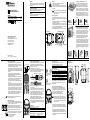
Anzugsdrehmoment
Klemmleiste/Schraubklemme max. 0,4 Nm
(empfohlenes Anzugsdrehmoment 0,3 Nm)
Verschraubung Bushaube max. 0,9 Nm
Anschlussbelegung
5-pol. Stecker (Datenleitung)
Pin 2 A Negative serielle Datenleitung
Pin 4 B Positive serielle Datenleitung
4-pol. Stecker (Betriebsspannung)
Pin 1 UB Betriebsspannung 10...30 VDC
Pin 3 GND Masseanschluss für UB
Klemmen mit gleicher Bezeichnung sind intern verbunden
und funktionsidentisch. Diese internen Klemmverbin-
dungen UB-UB und GND-GND dürfen mit max. je 1 A
belastet werden.
Anschluss – M12-Stecker (Bushaube)
Montageanleitung des Steckerlieferanten beachten.
- Steckverbinder auf Geräte-Stecker leicht andrücken.
- Steckverbinder vorsichtig drehen bis der Codiersteg in
die Codiernut der Steckerbuchse einrastet.
- Buchseneinsatz vollständig einführen.
- Überwurfmutter bis zum Anschlag anziehen.
Drehgeber-Gehäuse und Schirmgeecht des
Anschlusskabels sind nur dann optimal verbun-
den, wenn das Schirmgeecht grossächig im
Steckverbinder auiegt und die Überwurfmutter
fest angezogen ist.
- Bushaube vorsichtig auf die Grundplatte aufstecken,
dann über den Dichtgummi drücken und nicht verkan-
ten. Bushaube muss vollständig an Grundplatte anlie-
gen.
- Befestigungsschrauben gleichsinnig fest anziehen.
- Neigungssensorgehäuse und Schirmgeecht des An-
schlusskabels sind nur dann optimal verbunden, wenn
die Bushaube vollständig auf der Grundplatte auiegt
(Formschluss).
Anschluss – Kabelverschraubung
- Hutmutter der Kabelverschraubung lösen. Hutmutter
und Dichteinsatz auf den Kabelmantel schieben.
- Kabelmantel und Adern abisolieren, Schirmfolie, falls
vorhanden, kürzen (s. Bild).
- Schirmgeecht um ca. 90° umbiegen.
- Dichteinsatz bis an das Schirmgeecht schieben. Dicht-
einsatz und Kabel bündig in die Kabelverschraubung
einführen und Hutmutter fest verschrauben.
- Klemmen mit gleicher Bezeichnung sind intern mitein-
ander verbunden.
- Für die Betriebsspannung ausschliesslich Kabelver-
schraubung 3 verwenden. Für die Busleitungen können
frei wählbar Kabelverschraubung 1 oder 2 verwendet-
werden. Zulässige Kabelquerschnitte beachten.
- Adern auf dem kürzesten Weg in die Klemmleiste
einführen, zulässiger Adernquerschnitt beachten, bei
exiblen Adern Aderendhülsen verwenden.
- Überkreuzungen der Datenleitungen mit den Leitungen
der Betriebsspannung muss vermieden werden.
- Nicht benützte Kabelverschraubung mit Verschlussbol-
zen verschliessen (Lieferumfang). Die Hutmutter muss
fest verschraubt sein.
Aderquerschnitt
Eindrahtig (starr) Max. 1,5 mm
2
Feindrahtig (exibel) Max. 1,0 mm
2
Feindrahtig (exibel) Mit Aderendhülse max. 0,75 mm
2
Kabeldurchmesser
Kabelverschraubung 1, 2 8...10 mm (-40...+85 °C)
5...9 mm (-25...+85 °C)
Kabelverschraubung 3 4,5...6 mm
Printed in Germany
03.20 · 178.51.191/7 · 81005096
Baumer IVO GmbH & Co. KG
Dauchinger Strasse 58-62
DE-78056 Villingen-Schwenningen
Phone +49 7720 942-0
Fax +49 7720 942-900
www.baumer.com
GNAMG
Neigungssensor – Probus 2-8
Inclination sensor – Probus 9-16
Montageanleitung
Assembly Instructions
DE
EN
Elektrische Inbetriebnahme
- Neigungssensor elektrisch nicht verändern und keine
Verdrahtungsarbeiten unter Spannung vornehmen.
- Der elektrische Anschluss darf unter Spannung nicht
aufgesteckt oder abgenommen werden.
- Bei Verbrauchern mit hohen Störpegeln separate Span-
nungsversorgung für den Neigungssensor bereitstellen.
- Neigungssenor-Gehäuse und Anschlusskabel vollständig
schirmen.
- Die gesamte Anlage EMV gerecht installieren.
Einbauumgebung und Verkabelung beeinussen die
EMV des Neigungssensors.
- Neigungssensor und Zuleitungen räumlich getrennt oder
in grossem Abstand zu Leitungen mit hohem Störpegel
(Frequenzumrichter, Schütze usw.) verlegen.
- Sensorgehäuse und die Anschlusskabel vollständig-
schirmen.
- Neigungssensor an Schutzerde (PE) anschliessen. Ge-
schirmte Kabel verwenden. Schirmgeecht muss mit der
Kabelverschraubung oder Stecker verbunden sein. An-
zustreben ist ein beidseitiger Anschluss an Schutzerde
(PE). Gehäuse über den mechanischen Anbau erden,
bei elektrisch isoliertem Anbau zusätzliche Verbindung
herstellen. Kabelschirm über die nachfolgenden an-
geschlossenen Geräte erden. Bei Problemen mit Erd-
schleifen mindestens eine einseitige Erdung.
Bei Nichtbeachtung kann es zu Fehlfunktionen, Sach-
und Personenschäden kommen.
Elektrischer Anschluss
Bushaube ausschliesslich im ESD Beutel lagern und
transportieren. Bushaube muss vollständig an Grundplat-
te anliegen und fest verschraubt sein.
- Beide Befestigungsschrauben der Bushaube lösen
- Bushaube vorsichtig lockern und axial abziehen.
- Teilnehmeradresse an beiden dezimalen Drehschalter
einstellen. Teilnehmeradresse zum Beispiel 23.
- Abschlusswiderstände müssen beim letzten Teilnehmer
mit dem 2-poligen DIP Schalter auf „ON“ geschaltet
werden (Werkseinstellung OFF).
ON = Letzter Teilnehmer
OFF = Teilnehmer X
Montage
- Schläge oder Schocks auf Gehäuse vermeiden.
- Gehäuse nicht verspannen.
- Toleranzen bei der Montage von Bushaube und Grund-
platte können sich auf den absoluten Neigungswinkel
auswirken.
Gehäuse oder elektronische Teile können beschä-
digt werden. Die sichere Funktion ist dann nicht
mehr gewährleistet.
Mechanischer Anbau
- Beide Befestigungsschrauben der Bushaube lösen.
- Baushaube vorsichtig lockern und axial von Grundplatte
abziehen.
- Grundplatte des Neigungssensors an den Befestigungs-
bohrungen fest montieren.
- Bushaube muss plan über gesamten Umfang auf die
Grundplatte montiert werden. Toleranzen bei der Monta-
ge von Bushaube und Grundplatte können sich auf den
absoluten Neigungswinkel auswirken.
- Koordinatenausrichtung (y-/y+/x-/x+) siehe Zeichnung.
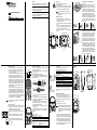
Einbaulage - Messbereich 15°, 30°, 60°
Der zweidimensionalen Neigungssensor für 15°,
30°, 60° muss so montiert werden, dass die
Grundplatte waagrecht, also parallel zur Hori-
zontalen, ausgerichtet ist. Der Neigungssensor
kann auch auf dem Kopf, d.h. um 180° gedreht,
eingebaut werden.Der Sensor kann gleichzeitig
in der X- und Y-Achse geneigt werden. Für beide
Achsen steht ein getrennter Messwert an. Im
Auslieferungszustand misst der Sensor in beiden
Achsen den gewählten Messbereich, z.B. ±15°,
wobei der Nulldurchgang genau in der Waagrech-
ten liegt.
Einbaulage - Messbereich 360°
Der 360º Neigungssensor muss so angebracht
werden, dass die auf dem Bild eingezeichnete
X-Achse parallel zur Erdanziehungskraft aus-
gerichtet ist. Die Auslenkung darf nicht mehr als
±3º betragen. Weiterhin ist zu beachten, dass
der Neigungssensor plan anliegt und während
der Neigung/Drehung keine Neigung in X- oder
Y-Richtung erfährt, da dies einen unmittelbaren
Einuss auf die Messgenauigkeit hat.
Im Auslieferungszustand des 360º Sensors ist die
0º Lage wie im folgenden Bild eingestellt, kann
aber mittels der Presetfunktion beliebig verändert
werden. Mittels Invertierung kann die Messrich-
tung umgekehrt werden. Im Auslieferungszustand
misst der Sensor im Uhrzeigersinn von 0...360º,
bei aktivierter Invertierung gegen den Uhrzeiger-
sinn.
Abmessungen
Kabelverschraubung
Stecker M12
Auslieferungszustand 0º gemessene Neigung 30º Auslieferungszustand 0º gemessene Neigung 30º
Auslieferungszustand 0º gemessene Neigung 45º gemessene Neigung 135º gemessene Neigung 180º
Y
X
Z
+
12 Kabel
Ader
Schirmgeflecht
5 18
Ader
Schirmfolie
Dichteinsatz
Schirmgeflecht KabelHutmutter
A
B
UB
GND
A
B
UB
GND
A
B
UB
GND
A
B
UB
GND
[
\
\±
[
[±
63
60
1
2
3
4
5
6
7
8
9
0
1
2
3
4
5
6
7
8
9
0
ON
12
1
3
4
5
2
4
3
5
1
2
1
3
4
2
M12-Stecker (Stift/
Buchse) für serielle Da-
tenleitung
M12-Stecker (Stift) für
Betriebsspannung
Allgemein
Bestimmungsgemässer Gebrauch, Inbetriebnahme, Mon-
tage, Entsorgung siehe Beileger «Allgemeine Hinweise»
(11042373).
Zusätzliche Informationen
Diese Montageanleitung ist eine produktspezische Er-
gänzung zu den allgemeinen Dokumenten.
Wartung
Der Sensor ist wartungsfrei und darf nicht mechanisch
oder elektrisch verändert werden.
y+
y–
x+
x–
Befestigungsbohrungen
Befestigungs-
schrauben
GrundplatteBushaube
Montagevariante

2 3 4
6 7 85
Locking torque
Terminal strip/screwing terminal max. 0.4 Nm
(recommended locking torque 0.3 Nm)
Connection bus cover max. 0.9 Nm
Pin assignment
5-pin connector (data line)
Pin 2 A Negative serial data line
Pin 4 B Positive serial data line
4-pin connector (supply voltage)
Pin 1 UB Supply voltage 10...30 VDC
Pin 3 GND Ground connection relating to UB
Terminals of the same signicance are internally con-
nected and identical in their functions. Max. load on the
internal terminal connections UB-UB and GND-GND is
1 A each.
Assignment – M12 connector
Follow also the instructions of the respective supplier.
- Press mating connector softly into the plug.
- Turn mating connector carefully until the code mark is
interlocking the corresponding space provided by the
plug.
- Insert bushing completely.
- Tighten the nut as far as possible.
An optimized connection between encoder case
and the braided shield of the connection cable is
only achieved by the braided shield being placed
generously onto the connector and the nut being
secured rmly.
- Plug the bus cover carefully onto the base plate, then
push it over the rubber seal. Avoid the case getting
wedged. The bus cover has to t tightly the base plate.
- Tighten both xing screws rmly and conformable.
- An optimized connection between inclination sensor
case and the braiding shield of the supply cable is only
achieved by a complete and close t of the bus cover
onto the base plate (interlock).
Connection – cable gland
- Unscrew cap nut of cable gland. Push cap nut and seal
insertion onto the cable coat.
- Strip isolation of cable coat and cores and cut shielding
foil, if any (picture).
- Bend the braided shield for about 90°.
- Push seal insertion to the braided shield. Insert seal
and cable ush into the cable gland. Secure by carefully
tightening the cap nut.
- Terminals of the same designation are internally con-
nected to each other.
- Use cable gland no. 3 for supply only. Cable glands No.
1 and 2 are for optional use as bus lines. Consider the
permitted cable cross-section.
- Use the shortest way to insert the cores into the termi-
nals and mind the maximum core cross-section. Use
core tip sleeves with exible cores.
- There must not be any crossing of data lines with lines
for power supply.
- Any cable gland not used has to be sealed by blind
plug (included into delivery). The cap nut must be rmly
tightened.
Core cross-section
Single wire (rigid) Max. 1.5 mm
2
Fine wire (exible) Max. 1.0 mm
2
Fine wire (exible) With ferrule max. 0.75 mm
2
Cable diameter
Cable gland 1, 2 8...10 mm (-40...+85 °C)
5...9 mm (-25...+85 °C)
Cable gland 3 4.5...6 mm
cablecap nut
wire
screen film
seal
screen
Assembly
- Avoid punches or shocks on the housing.
- Avoid case distortion.
- The bus cover must fully and evenly rest on the base
plate. Any tolerances in mounting the bus cover to the
base plate may affect the absolute slope angle.
Housing or electronic components might be
damaged and a secure operation is no longer
guaranteed.
Mechanical mounting
- Release both fastening screws of the bus cover.
- Carefully loosen the bus cover from the base plate and
lift off in the axial direction.
- Firmly screw the base plate in place using the fastening
holes.
- The bus cover must fully rest against the base plate.
Any tolerances in mounting the bus cover to the base
- plate might affect the absolute slope angle.
- Alignment of coordinates (y- / y+ / x- / x+) see following
diagram:
GNAMG
Inclination sensor – Probus 9-16
Assembly Instructions
EN
Installation position - Measuring range
15°, 30°, 60°
The two-dimensional inclination sensor featuring
a sensing range of 15°, 30° and 60° must be
installed with the base plate in horizontal position,
i.e. parallel to the horizontal line. The inclination
sensor may also be installed upside down, i.e.
turned by 180°. The sensor can be inclined both in
lateral (X-axis) and longitudinal (Y-axis) direc-
tion at the same time. For each axis a separate
measured value is provided. As default parameter
the inclination sensor will apply the selected sen-
sing range to both the X and Y- axis, for example
±15° with the zero passage being precisely in the
horizontal line.
Installation position - Measuring range 360°
The inclination sensor featuring a 360º sensing
range must be installed in a way that the X-axis
as in the illustration is in parallel alignment with
gravity. The deection may not be more than
±3°. Please note that the inclination sensor must
fully and evenly rest on the contact surface and
whilst inclination/rotation must not be subject to
any misalignment in the X- or Y-direction since
this would affect the sensing accuracy. The 360°
inclination sensor default position is 0° as shown
in the following illustration but may be optionally
congured by help of the preset function. The
measuring direction may also be inverted. Default
parameter of the inclination sensor´s sensing
direction is clockwise from 0...360°, in case of ac
tive inversion counter-clockwise.
Default 0º Measured inclination 30º Default 0º Measured inclination 30º
Default 0º Measured inclination 45º Default 135º Measured inclination 180º
Y
X
Z
+
Dimensions
Cable gland
Connector M12
[
\
\±
[
[±
63
60
Electrical installation
- Do not modify inclination sensor in any electrical way
and carry out any wiring work under power supply.
- Any electrical connection and plugging-on whilst under
power supply is not permitted.
- A separate inclination sensor supply has to be provided
with consumers with high interference emission.
- Installation of the whole system has to be according to
EMC standards. Installation environment as well as wi-
ring have an impact on the inclination sensor’s EMC. In-
clination sensor and supplying lines are to be in separa-
ted locations or remote from lines with high interference
emission (frequency transformers, protections, etc.).
- Inclination sensor case and supply cable have to be
completely screened.
- Ground (PE) inclination sensor by using screened ca-
bles. The braided shield has to be connected to cable
gland or plug. Grounding (PE) on both sides is recom-
mended. Ground the case by the mechanical assembly,
if latter is electrically isolated a second connection has
to be provided. Ground cable screen by the subsequent-
ly connected devices. In case of ground loop problems
at least grounding on one side is imperative.
Any disregard may lead to malfunctions, material damage
and personal injury.
Electrical connection
The bus cover is to be stored and transported whilst in the
ESD bag only. The bus cover has to t the base plate ti-
ghtly and has to be rmly secured by screws.
- Unscrew both xing screws of the bus cover.
- Loosen bus cover carefully and remove it in axial direc-
tion.
- Adjust participant address at the two decimal rotary
switches. The participant’s address for example 23.
- For the last participant the terminators are to be swit-
ched “ON” by means of the 2-pin Dip switch (default
OFF).
ON = nal user
OFF = user X
1
2
3
4
5
6
7
8
9
0
1
2
3
4
5
6
7
8
9
0
12 Cable
Wire
Screen
5 18
ON
12
1
3
4
5
2
4
3
5
1
2
1
3
4
2
M12 connector (male/
female) for data line
M12 connector (male)
for supply voltage
A
B
UB
GND
A
B
UB
GND
A
B
UB
GND
A
B
UB
GND
1 2 3
General
Instructions for appropriate use, set-up, installation, dispo-
sal see insert «General Information» (11042373).
Additional informations
These assembly instructions are a product-specic sup-
plement to the general documents.
Maintenance
The sensor is maintenance-free and must not be mecha-
nically or electronically modied.
y+
y–
x+
x–
fastening holes
fastening
screws
base platebus cover
Mounting version
-
 1
1
-
 2
2


Baumer GNAMG Installation and Operating Instructions
- Typ
- Installation and Operating Instructions
in anderen Sprachen
- English: Baumer GNAMG
Verwandte Artikel
-
Baumer GNAMG Installation and Operating Instructions
-
-
-
Baumer GBAMS Installation and Operating Instructions
-
-
Baumer GBMMH Installation and Operating Instructions
-
-
-
-