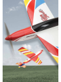
Ripmax Easy Street 2 Benutzerhandbuch
- Kategorie
- Ferngesteuertes Spielzeug
- Typ
- Benutzerhandbuch

Instruction Manual
Bauanleitung
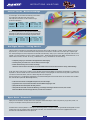
Specification:
Wingspan: 1120mm (44”)
Length: 970mm (38”)
Flying weight: 1170-1280g (2.6-2.8Ibs)
Radio: 4-5 Channel* Servos: 4x Mini*
*
(Recommendation, not included)
Technische Daten:
Spannweite: 1120mm
Länge: 970mm
Fluggewicht: ca. 1170-1280g
Fernsteuerung: 4...5-Kanal* Servos: 4x Mini*
*
(empfohlen aber nicht enthalten)
A-ARTF6730


CONTENTS INHALT PAGE / SEITE
General Notices Wichtige Hinweise 2 / 3
Contents
Required to Complete
Inhalt
erforderliches Zubehör
4
4
Stages Schritte 5 - 19
Completed Model
Balancing
Fertiges Modell
Schwerpunkt
19
19
Control Throws
Pre-Flight Checks
Spare Parts
Ruderausschläge
Vorflug Checks
Ersatzteile
20
20
20
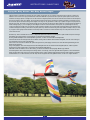
Flying the Easy Street 2 Den Easy Street 2 Fliegen 21

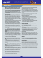
General Notices
INSTRUCTIONS / ANLEITUNG
2
Make sure you read this safety information and the instructions
before building your model. Follow exactly the recommended
procedures and settings given in the instructions.
If you are operating a radio-controlled model aircraft, helicopter,
car, multicopter or boat for the first time, we recommend that you
enlist the help of an experienced modeller to guide you. There
are also special clubs or modeling associations that offer training
services and assistance.
Safety Information
Radio-controlled models are not toys in the usual sense, and
young people under 14 years of age should not operate them
unless supervised by an experienced adult. It is advised not to
operate model multicopters, model helicopters, model aircraft or
model boats commercially without official permission. But you
are allowed to operate them for sports and recreational purposes,
sometimes authorisation from the local council may be required
to use a model in certain locations
The building and operating of models requires technical expertise,
manual skill, a careful attitude and use of safety-conscious
behavior. Errors, negligence and omissions in building or flying
these models can result in serious personal injury or damage
to property. Changes to the construction and deviating from the
operating manual will invalidate any warranty or liability claims.
Since the manufacturers and vendors of the equipment have
no means of checking that your models are built and operated
correctly, we explicitly bring your attention to these risks and deny
all further liability.
A properly constructed model may still be dangerous if
used incorrectly. Never reach into rotating propellers /
blades or other moving parts as this may cause serious
injuries. Note that motors, controllers and exhaust systems can
reach high temperatures during operation. Avoid all contact with
such parts.
The tools needed for assembly can also cause injuries. Even
metal or plastic parts which are broken or untrimmed can cause
injuries. Adhesives and paints may contain hazardous substances
like solvents etc. Please observe the manufacturer's information
and wear safety equipment (goggles, gloves etc.) when necessary.
Rubber parts (e.g. rubber bands) may become old and brittle and
fail. Such parts have to be checked before use.
Keep well clear of the electric motors and all moving
components when the battery is connected. Mistakes
happen and in spite of all safety precautions and there is
always a risk of damage and injury from parts such as propellers
or rotors. For example, by you may unintentionally move the
throttle stick on the transmitter during setup. Also ensure that
other hazards such as pets are not able to come in contact with
moving parts!
Never y a model aircraft, helicopter or multicopter at eye
level directly in line with other people/animals as this
will increase the risk of injury. Always keep yourself at a
safe distance from your model and pay particular attention while
take-off and landing for obstacles.
Observe the instructions of the battery and charger manufacturer.
Use only recommended battery chargers and recharge your battery
only until the specied charging time/level. Excess or incorrect
charging methods can lead to the battery exploding. Pay extra
attention to ensure correct polarity.
Protect your equipment from dust, dirt and moisture. Do not
expose the device to excessive heat, cold or vibration. The remote
control operation may be performed only within the specied
temperature range, avoid unusually hot/cold days.
Check your equipment regularly for damage and always replace
damaged components with original spare parts.
Don't re-use any equipment or devices which have been subject
to crash or water damage. Either return to the Service Department
for repair or replace. Hidden problems may occur after crash or
water damage which can lead to problems or total failure later in
operation.
Use only recommended components and accessories. On remote
control systems no changes may be made.
Routine Pre-Flight Checks
• Before switching on the receiver, ensure that the throttle
control on the transmitter is in the motor stop position.
• Always switch on the transmitter first and then the receiver.
• Always switch off the receiver first, then the transmitter.
• Before use perform a range test.
• Check if the correct model memory is selected.
• Perform a function test before each use, ensuring to check the
direction of travel, movement and all other functions including
mixing functions and default switch positions.
• Ensure all batteries are fully charged.
Operating the Model
• Never fly over or towards spectators or other pilots and
maintain a safe distance at all times.
• Never endanger people or animals!
• Never fly close to high-tension overhead cables or populated
areas.
• Do not operate your model in the vicinity of canals, locks or
open waterways.
• Do not operate your model from public roads, motorways, paths
and squares etc. Only at authorised spaces.
• Do not operate your models in thunderstorms as they could
interfere with the radio remote control systems.
Aerial Position
Never “point” the transmitter aerial straight at the model when
in operation. The signal generated by the transmitter is at its
weakest in an imaginary line extending straight from the aerial. It
is always best for the pilot to stand in a position where the long
side of the aerial points towards the model.
Insurance
Ground-based models are usually covered by standard personal
third-party insurance policies. For flying models additional
insurance is recommended. Check your insurance policy that you
are suitably covered and abode by its guidelines.
Liability Exclusion:
We have no control over the use of this product outside of the
parameters of the instructions, regarding methods of assembly/
installation, operation, misuse and poor maintenance of the
product or it’s components. Therefore, we assume no liability for
any loss, damage or costs arising from the improper use/operation.
Ripmax shall not be liable for any loss, consequential loss, damage
or expense arising from the improper use or operation in anyway.
In as far as legally permitted, compensation shall be limited to
the invoice value of the Ripmax products directly involved in the
damage-causing event. This does not affect your statutory rights.

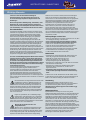
Wichtige Hinweise
INSTRUCTIONS / ANLEITUNG
3
Lesen Sie vor dem Bau Ihres Modells unbedingt die
Sicherheitshinweise genau durch. Halten Sie sich stets an
die in den Anleitungen empfohlenen Vorgehensweisen und
Einstellungen.
Wenn Sie ferngesteuerte Modellfugzeuge, -hubschrauber, -autos
Multikopter oder -schiffe erstmalig betreiben, empfehlen wir
Ihnen, einen erfahrenen Modellpiloten um Hilfe zu bitten. Vereine
oder die Modellflug- oder Carverbände können diese vermitteln.
Sicherheitshinweise
Ferngesteuerte Modelle sind kein Spielzeug im üblichen Sinne
und dürfen von Jugendlichen unter 14 Jahren nur unter Aufsicht
von Erwachsenen eingesetzt und betrieben werden. Modell-
Multicopter, Modell-Hubschrauber, Flug- oder Schiffsmodelle
dürfen ohne entsprechende Genehmigung nicht gewerblich
eingesetzt werden, nur zum Zweck des Sports und der
Freizeitgestaltung. Einzelgenehmigungen erteilt das für das
Fluggebiet zuständige Regierungspräsidium. Der Bau und Betrieb
erfordert technisches Verständnis, handwerkliche Sorgfalt und
sicherheitsbewusstes Verhalten. Fehler oder Nachlässigkeiten
beim Bau, Fliegen oder Fahren können erhebliche Sach- oder
Personenschäden zur Folge haben. Änderungen des Aufbaus und
Nichteinhalten der Betriebsanleitung führen zum Verlust jeglicher
Gewährleistungs-oder Haftungsansprüche. Da Hersteller und
Verkäufer keinen Einfluss auf den ordnungsgemäßen Bau und
Betrieb der Modelle haben, wird ausdrücklich auf diese Gefahren
hingewiesen und jegliche Haftung ausgeschlossen.
Auch vom vorschriftsmäßig aufgebauten Modell können Gefahren
ausgehen. Greifen Sie niemals in sich drehende Luftschrauben/
Rotorblätter oder sonstige, offenliegende, sich bewegende Teile,
da ansonsten schwerwiegende Verletzungen entstehen können.
Beachten Sie, dass Motoren, Regler und Auspuffanlagen im Betrieb
hohe Temperaturen erreichen können. Vermeiden Sie unbedingt
eine Berührung solcher Teile.
Von den für den Zusammenbau notwendigen Werkzeugen
kann Verletzungsgefahr ausgehen. Ebenfalls besteht
Verletzungsgefahr bei abgebrochenen oder nicht entgrateten
Metall- oder Plastikteilen. Klebstoffe und Lacke können
gesundheitsgefährdende Substanzen wie Lösungsmittel usw.
enthalten. Beachten Sie die Herstellerhinweise und tragen Sie
ggfls. eine Schutzbrille. Gummiteile wie z. B. Gummiringe können
altern, spröde und unbrauchbar werden und müssen vor Gebrauch
getestet werden.
Bei Elektromotoren mit angeschlossenem Antriebs- oder
Empfängerakku niemals im Gefährdungsbereich von
Luftschrauben oder rotierenden Teilen aufhalten. Es
könnte trotz aller Sicherheitsvorkehrungen zum Anlaufen von
Propeller oder Rotoren kommen, z.B. durch unbeabsichtigtem
Verstellen des Leistungs/Gasknüppels am Fernsteuersender.
Achten Sie ebenfalls darauf, dass keine sonstigen Gegenstände
mit sich drehenden Teilen in Berührung kommen! Denken Sie
auch an Ihre Haustiere!
Fliegen Sie grundsätzlich, ob mit Modellflugzeugen-,
Hubschraubern- oder Multicoptern, nie in Augenhöhe
direkt auf sich oder andere Personen oder Tiere zu, es
besteht erhebliche Verletzungsgefahr. Halten auch Sie selber
immer einen ausreichenden Sicherheitsabstand zu Ihrem Modell.
Achten Sie auf freie Start- und Landeflächen.
Beachten Sie die Hinweise der Akku- und
Ladegerätehersteller.
Benutzen Sie nur empfohlene Ladegeräte und laden
Sie Ihre Akkus nur bis zur angegebenen Ladezeit. Über- oder
Falschladungen können zur Explosion der Akkus führen. Achten
Sie auf richtige Polung. Über- oder Falschladungen können zur
Explosion der Akkus führen. Achten Sie auf richtige Polung.
Schützen Sie Ihre Geräte vor Staub, Schmutz und Feuchtigkeit.
Setzen Sie die Geräte keiner übermäßigen Hitze, Kälte oder
Vibrationen aus. Der Fernsteuerbetrieb darf nur im angegebenen
Temperaturbereich durchgeführt werden. Überprüfen Sie Ihre
Geräte stets auf Beschädigungen und erneuern Sie defekte
Komponenten mit Original-Ersatzteilen. Durch Absturz
beschädigte oder nass gewordene Geräte, selbst wenn sie
wieder trocken sind, nicht mehr verwenden! Entweder im
Service überprüfen lassen oder ersetzen. Durch Nässe oder
Absturz können versteckte Fehler entstehen, welche nach kurzer
Betriebszeit zu einem Funktionsausfall führen. Es dürfen nur die
von uns empfohlenen Komponenten und Zubehörteile eingesetzt
werden. An Fernsteueranlagen dürfen keinerlei Veränderungen
vorgenommen werden.
Routineprüfungen vor dem Start
• Bevor Sie den Empfänger einschalten vergewissern Sie sich, dass
der Gasknüppel auf Stopp / Leerlauf steht.
• Immer zuerst den Sender, dann den Empfänger einschalten.
• Immer zuerst den Empfänger, dann den Sender ausschalten.
• Führen Sie vor dem Start einen Reichweitentest durch.
• Prüfen Sie, ob der korrekte Modellspeicher ausgewählt ist.
• Führen Sie einen Funktionstest durch. Prüfen Sie die
Laufrichtung und die Ausschläge aller Funktionen am Modell.
• Sind Mischfunktionen und Schalter richtig eingestellt?
• Ist der Ladezustand der Akkus ausreichend?
Modellbetrieb
• Überfliegen Sie niemals Zuschauer oder andere Piloten und
halten Sie genügend Sicherheitsabstand zu Ihrem Modell.
• Gefährden Sie niemals Menschen oder Tiere.
• Fliegen oder fahren Sie nie in der Nähe von
Hochspannungsleitungen oder Wohngebieten.
• Betreiben Sie Ihr Modell auch nicht in der Nähe von Schleusen
und öffentlichem Schiffsverkehr.
• Betreiben Sie Ihr Modell nicht auf öffentlichen Straßen,
Autobahnen, Wegen und Plätzen etc., sondern nur an
zugelassenen Orten.
• Bei Gewittern dürfen Flugmodelle generell nicht betrieben
werden, Gewitterspannungen könnten die Funkfernsteuerung
stören.
Im Betrieb nicht mit der Senderantenne auf das Modell ‘zielen’.
In dieser Richtung hat der Sender die geringste Abstrahlung. Am
Besten ist die seitliche Stellung der Antenne zum Modell.
Versicherung
Bodengebundene Modelle sind üblicherweise in einer
Privathaftpflichtversicherung mitversichert. Für Flugmodelle ist
eine Zusatzversicherung oder Erweiterung erforderlich.
Überprüfen Sie Ihre Versicherungspolice und schließen sie ggf.
eine Versicherung ab.
Haftungsausschluss:
Ripmax Produkte sind häufig nur ein Teil einer ganzen
Funktionskette. Diese Funktionskette, wie auch die Einhaltung der
Montage und Betriebsanleitung als auch die Bedingungen und
Methoden bei Installation, Betrieb, Verwendung und Wartung der
Modellbaukomponenten können von Ripmax nicht überwacht
werden. Dafür ist immer der Pilot alleine verantwortlich. Daher
übernehmen wir keinerlei Haftung für Verluste, Schäden oder
Kosten, die sich aus fehlerhafter Verwendung und Betrieb ergeben
oder in irgendeiner Weise damit zusammenhängen. Soweit
gesetzlich zulässig ist die Verpflichtung zur Schadenersatzleistung,
gleich aus welchen Rechtsgründen, auf den Rechnungswert der an
dem schadensstiftenden Ereignis unmittelbar beteiligten Ripmax-
Produkte begrenzt. Dies gilt nicht, soweit nach zwingenden
gesetzlichen Vorschriften wegen Vorsatzes oder grober
Fahrlässigkeit unbeschränkt gehaftet werden muss.

Recommended
Empfohlen
1
5
3
4
7
8
6
9
10
2
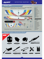
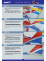
Parts List:
1
Wings.
2
Fuselage.
3
Tailplane.
4
Fin and Rudder.
5
Canopy.
6
Fibreglass cowl.
7
Wing spar.
8
Spinner.
9
Control rods.
10
Accessories.
Teileliste:
1
Tragfläche
2
Rumpf
3
Höhenleitwerk
4
Seitenleitwerk
5
Kabinenhaube
6
GFK Motorhaube
7
Steckungsrohr
8
Spinner
9
Anlenkungen
10
Kleinteile
Contents / Inhalt
Required to Complete / Erforderliches Zubehör
INSTRUCTIONS / ANLEITUNG
4
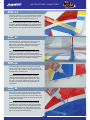
Take a moment to identify each of the parts supplied and read through these
instructions before commencing assembly.
Prüfen Sie die Teile vor dem Zusammenbau und lesen Sie die Bauanleitung.
Radio: 4-6 channel
1
Fernsteuerung:
4...5 Kanal
Servos: 4 x New Power
17 (P- XLD-17MB)
2
Servos: 4 x New Power
17 (P- XLD-17MB)
Li-po Battery: 3S1P or 4S1P
2200mAh to 3000mAh 30C
5
LiPo Akku: 3S1P oder 4S1P
2200 bis 3000mAh 30C
Extension lead: 2 x
200mm (AILERONS)
7
Verlängerungskabel: 2x
200mm (f. Querruder)
Various hand tools
8
Diverse
Handwerkzeuge
Cyano and Epoxy glue
9
Sekundenkleber und
Epoxy
EP Motor: Quantum II 25S
(M-Q2-25S)
3
EP Motor: Quantum II 25S
(M-Q2-25S)
Speed Controller: Quantum 60 AMPS with
5V BEC (P-QESC60S)
4
Regler: Quantum 60A mit 5V BEC
(P-QESC60S)
Propeller: 3S = APC 10x7” EP
(E-LP10070E)
4S = APC 9x7.5” EP (E-LP09075E)
6
Propeller: 3S = APC 10x7” EP
(E-LP10070E)
4S = APC 9x7.5” EP (E-LP09075E)

Stage
Schritt
2
Stage
Schritt
1
Stage
Schritt
3
INSTRUCTIONS / ANLEITUNG
5
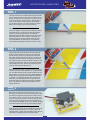
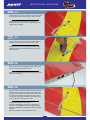
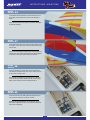
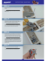
Remove the covering in the servo plate for the servo arm, and
then install one of the aileron servos to the mounting plate, using
the wooden mounting blocks, making sure that the servo output
arm is central in the slot, as shown. This can be a bit tight in the
servo box in the wing, so take care to make sure that it is square
on the servo plate. Screw the aileron servos into position using
the mounting screws supplied with your servo. Note that the output
arms face towards the rear of the wing and towards the wingtip.
Entfernen Sie die Folie über den Ausschnitten für die Servoarme.
Schrauben Sie die Querruderservos in Position, so dass die
Servohebel mittig im Schlitz sitzen. Beachten Sie dabei, dass die
Servohebel zur Flügelhinterseite und nach außen zeigen.
Carefully slide each aileron into position, ensuring a gap-free
hinge line. Make sure that each aileron lines up with the wing
tips and that they are free to move through their entire travel.
Centre each aileron between the root and tip so that there is an
equal gap at both ends. Minimise any hinge gap, then carefully
add a couple of drops of thin cyano to the top and bottom of each
hinge ensuring that the glue does not run through the hinge line
onto the bottom of the wing. Turn the wing over and drop more
cyano onto each hinge from the other side.
Schieben Sie jedes Querruder vorsichtig in Position, und stellen
Sie sicher, dass diese spaltfrei eingebaut sind. Vergewissern Sie
sich, dass jedes Querruder korrekt zwischen der Wurzel und der
Spitze zentriert wird, und dass sich diese zu jedem Zeitpunkt frei
bewegen können. Fügen Sie ein paar Tropfen Sekundenkleber
auf die Ober - und Unterseite der Scharniere, und achten Sie
dabei darauf, dass der Klebstoff nicht in den Spalt an der Un-
terseite des Flügels läuft. Drehen Sie den Flügel anschließend
herum, und tropfen Sie nochmals Sekundenkleber auf diese
Seite der Scharniere.
The wings and ailerons are supplied with the hinges loose fitted,
ready for installation. Remove both ailerons and ensure that the
hinges are inserted mid-way in their slots. Using thin cyano, pour
a drop onto each hinge – above and below – ensuring the glue
soaks into the hinge and surrounding wood on both ailerons.
(Top Tip) When using thin cyano (super glue) little and often is
better as this will stop any cyano runs on the airframe.
Die Flügel und die Querruder werden mit lose montierten
Scharnieren geliefert, und sind fertig für die Montage. Entfernen
Sie beide Querruder, und achten darauf, dass die Scharniere
mittig in den Schlitzen ausgerichtet sind. Verwenden Sie
dünnflüssigen Sekundenkleber. Kleben Sie mit ein paar Tropfen
Kleber jedes Scharnier, -oben und unten- in die Fläche, und
stellen Sie sicher, dass sich der Klebstoff mit dem Scharnier
und demumgebenden Holz verbunden hat. (Tipp) Wenn Sie
dünnflüssigen Sekundenkleber verwenden, ist dies von Vorteil.

Stage
Schritt
7
Stage
Schritt
6
Stage
Schritt
5
Stage
Schritt
4
6
INSTRUCTIONS / ANLEITUNG
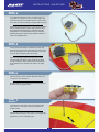
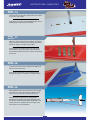
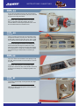
Install the aileron servo hatch using 4 screws supplied taking
care to ensure it is fitted on the correct side and the colour
scheme matches.
Nun befestigen Sie den Servodeckel mit den vier mitgelieferten
Schrauben. Achten Sie darauf, dass dieser an der richtigen Seite
angebracht ist, und zum Farbschema passt.
Check that the servo arm is centred at 90 degrees to the servo
case with your radio switched on.
Mit eingeschaltetem Sender, überprüfen Sie ob der Servoarm im
90° Winkel zum Servogehäuse steht.
Carefully pull the lead through to the centre of the wing using
the string. Pull out the servo connector through to the hole in the
bottom of the wing then retain the servo lead with a short length
of tape to stop the lead pulling back into the wing.
Ziehen Sie vorsichtig die Kabel durch die Mitte des Flügels,
unter Verwendung des Fadens. Heben Sie den Servo Stecker
aus dem Loch heraus, dann umwickeln Sie das Servokabel mit
etwas Klebeband, damit das Kabel nicht wieder in den Flügel
rutscht.
Fit suitable 200mm extension leads to your aileron servo. It is
a good idea to use a lead-lock, a turn of insulation tape or heat
shrink tube over the joint for additional security. Carefully tie the
end of each servo lead to the length of string installed in the wing.
Bereiten Sie Ihre Querruder Servos vor, indem Sie ein passendes
200mm Verlängerungskabel mit jedem Servo verbinden. Es ist
eine gute Idee eine Steckersicherung, Isolierband oder einen
Schrumpfschlauch zur zusätzlichen Sicherung zu verwenden.
Befestigen Sie an jedem Querruder Servokabel den Faden, der
schon in der Flügelhälfte liegt.

Stage
Schritt
11
Stage
Schritt
10
Stage
Schritt
9
Stage
Schritt
8
7
INSTRUCTIONS / ANLEITUNG
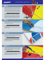
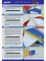
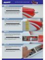
Locate a threaded wire aileron pushrod and attach a nylon clevis
to the end. Connect it to the aileron horn and mark the position
the control rod passes over the servo’s output arm. Bend the
pushrod up at 90° at this point.
Nehmen Sie das Querrudergestänge mit Gewinde und befestigen
am Ende einen Kunststoff Gabelkopf. Verbinden Sie diesen mit
dem Ruderhorn und markieren Sie die Position des Servohebels.
Biegen Sie das Gestänge an diesem Punkt um 90°.
Use a small length of tape to hold each of the ailerons in their
neutral position while you complete the aileron linkages. Ensure
that both aileron servos are still centred.
Verwenden Sie etwas Klebeband, um jedes Querruder in
ihrer Neutralposition zu halten, während Sie die Querruder
Anlenkungen vervollständigen. Vergewissern Sie sich, dass
beide Querruder zentriert sind.
Do not overtighten the control horn mounting screws as you don’t
want to crush the aileron. Turn the model over and trim off any
excess thread using side cutters.
Nicht die Ruderhornschrauben überdrehen - Sie möchten
ja nicht das Querruder zerdrücken. Drehen Sie das Modell
herum, und schneiden das überschüssige Gewinde mit einem
Seitenschneider ab.
Locate the aileron control horns and screws. They are screwed
into position on the ailerons inline with the aileron servos output
arm through the hardwood block. Align the row of holes in the
horn with the hinge line. Mark and pilot drill two mounting holes
then screw the horn to the aileron. The screws thread into the
moulded horn plate positioned on the top surface of the wing.
Nehmen Sie die Ruderhörner. Diese werden in einer Linie mit
dem Servoabtrieb durch den Hartholzblock festgeschraubt.
Richten Sie die Löcher im Ruderhorn mit der Scharnierlinie
aus. Markieren und Bohren Sie zwei Löcher und schrauben
diese dann am Querruder fest. Die Schrauben werden in die
Trägerplatte auf der Oberseite des Ruders eingeschraubt.

Stage
Schritt
15
Stage
Schritt
14
Stage
Schritt
13
Stage
Schritt
12
INSTRUCTIONS / ANLEITUNG
8
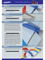
Adjust the pushrods to ensure that the ailerons are centred with
the aileron servos at their neutral position. Test to ensure that
both ailerons move freely across their entire throw. Note that we
have fitted short lengths of fuel tube over the clevis to ensure
it cannot open under flight loads. Repeat the procedure for the
second wing in exactly the same way as shown.
Stellen Sie die Gestänge so ein, dass die
Querruder in Neutralposition zentriert sind. Testen Sie die
Querruder auf freie Beweglichkeit über den kompletten Weg.
Sichern Sie die Gabelköpfe, wie gezeigt, mit einem kurzen Stück
Schlauch.
Wiederholen Sie dies auch für das zweite Querruder.
Now locate the wing anti-rotation pegs and epoxy these into the
front and rear of each wing panel as shown.
Kleben Sie die Verdrehsicherungen wie gezeigt mit Epoxy vorne
und hinten in die Flächen.
Trim off the excess pushrod wire using side cutters. Repeat the
procedure for the second aileron in exactly the same way.
Schneiden Sie das überschüssige Gestänge mit einem Seiten-
schneider ab. Wiederholen Sie dieses Verfahren auch für das
zweite Querruder
Slide the aileron servo horn over the wire, re-fit to the servo and
snap a moulded keeper onto the pushrod to retain it as shown.
Schieben Sie das Querruder Servohorn über den Draht,
befestigen Sie dies wieder am Servo, und befestigen Sie einen
Sicherungsclip, wie gezeigt.

Stage
Schritt
19
Stage
Schritt
18
Stage
Schritt
17
Stage
Schritt
16
INSTRUCTIONS / ANLEITUNG
9
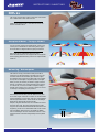
Slide the tailplane into its precut slot in the rear of the fuselage.
Ensure that it is square to the fuselage and centred in its slot
using a long ruler or string as shown in the diagram right.
Schieben Sie das Heckleitwerk in die vorgeschnittenen
Steckplatz an der Rückseite des Rumpfes. Stellen Sie sicher,
dass dieses im rechten Winkel zum Rumpf ausgerichtet ist, und
mittig im Schlitz sitzt. Verwenden Sie dazu ein langes Lineal,
oder eine Schnur, wie in dem Diagramm.
Locate the slots at the rear of the fuselage for the tailplane and
carefully trim the covering away.
Finden Sie die Einbauschlitze für das Höhenleitwerk an der
Rückseite des Rumpfes und schneiden vorsichtig die Folie ab.
There are a series of cooling holes in underside of the fuselage.
Using a knife remove the film from these openings to aid airflow
through the cowling over the battery and out again.
Auf der Unterseite des Rumpfes befinden sich einige Entlüf-
tungsöffnungen. Entfernen Sie die Folie, sodass die Kühlluft
durch die Motorhaube über den Akku und wieder aus dem Rumpf
strömen kann.
Cut the film away from the wing mounting holes and the bolt hole
on both sides of the fuselage.
Entfernen Sie die Folie über den Flächenbefestigungen sowie für
die Befestigung auf beiden Seiten des Rumpfes.

Stage
Schritt
23
Stage
Schritt
22
Stage
Schritt
21
Stage
Schritt
20
INSTRUCTIONS / ANLEITUNG
10
Insert two hinges in each elevator half, ensuring they are located
mid-way in their slots. Using thin cyano, pour a couple of drops
onto each hinge - above and below - ensuring the glue soaks into
the hinge and the surrounding wood.
Schieben sie zwei Scharniere in jede Höhenruderhälfte, und
stellen Sie sicher, dass diese bis zur Hälfte hinein geschoben
sind. Verwenden Sie dünnflüssigen Sekundenkleber, und kleben
mit ein paar Tropfen Sekundenkleber jedes Scharnier - oben und
unten - in den Schlitz. Stellen Sie sicher, dass sich der Klebstoff
mit dem Scharnier und dem umgebenden Holz verbunden hat.
Roughen the wire elevator joiner to increase the bond strength
in the next step. Now loosely position the joiner at the rear of the
tailplane slot. Using epoxy applied to the exposed wood, glue
the tailplane into its slot. Check that the tailplane is correctly
aligned and square to the fuselage. Use masking tape to protect
the covering whilst you do this (removing it as soon as you are
satisfied with the alignment and before the epoxy cures). Any
excess epoxy can be wiped from the model before it cures using
methylated spirit or methanol.
Rauen Sie den Höhenruderstift an, um die Haftfestigkeit im
nächsten Schritt zu erhöhen. Nun schieben Sie den Stift
lose in die Rückseite des Leitwerkschlitzes. Bestreichen Sie
das freiliegende Holz mit Epoxidharz Kleber, und kleben das
Höhenleitwerk in seinen Schlitz. Überprüfen Sie, dass das
Leitwerk korrekt angeglichen wurde, und im rechten Winkel
zum Rumpf steht.Verwenden Sie Abdeckband, um die Folie zu
schützen, während Sie dieses machen. Entfernen Sie das Band,
bevor das Harz aushärtet. Den überschüssigen Kleber auf dem
Modell kann man mit Methanol oder Spiritus entfernen.
Remove the tailplane and cut away the covering from just inside
the marked lines to give a film-free surface for the glue to bond.
IMPORTANT: Ensure that only the film is cut - not the tailplane
as this will seriously weaken the structure.
Nehmen Sie das Heckleitwerk wieder heraus, und schneiden
die Folie an der Innenseite der markierten Linie mit einem
Messer weg, um eine saubere Fläche für die Verklebung zu
schaffen. WICHTIG: Vergewissern Sie sich, dass nur die Folie
durchgeschnitten ist – nicht das Leitwerk- da dieses die Stabilität
ernsthaft schwächt.
Mark the tailplane on the top and bottom where it enters the
fuselage using a soft, water- soluble pen.
Markieren Sie mit einem wasserlöslichen Stift das Heckleitwerk
auf der Ober- und Unterseite, wo es in den Rumpf geht.

Stage
Schritt
27
Stage
Schritt
26
Stage
Schritt
25
Stage
Schritt
24
INSTRUCTIONS / ANLEITUNG
11
Repeat the procedure for the second elevator half and tape into
position, ensuring that both elevator halves are level with each
other
Wiederholen Sie die Schritte für das zweite Höhenruder.
Protecting the rear of the tailplane with a strip of masking tape,
apply epoxy to one half of the wire elevator joiner and force
it into the corresponding slot and hole in the elevator half.
Now slide the first elevator into position ensuring that the joinr
and both hinges enter their pre-cut slots/hole in the tailplane/
elevator. Ensuring a gap-free hinge line and a 1mm gap between
the elevator and tip, add a couple of drops of thin cyano to the
top and bottom of each hinge. Make sure that the glue does not
run through the hinge line onto the bottom of the tail. Turn the
model over and drop more cyano onto each hinge from the other
side.
Verwenden Sie einige Streifen Abklebeband, um die Rückseite
des Rumpfes zu schützen. Bestreichen Sie die eine Hälfte des
Höhenruder Verbinder mit Epoxidharz ein, und drücken diesen
in das Loch in der Höhenruderhälfte ein. Nun schieben Sie
das erste Höhenruder in Position, und vergewissern sich, dass
der Verbinder und beide Scharniere in ihren vorgeschnittenen
Schlitze/Löcher im Leitwerk/Höhenruder hinein geschoben sind.
Stellen Sie sicher, dass diese spaltfrei und 1mm zwischen dem
Höhenruder und der Spitze hinein geschoben sind. Fügen Sie
ein paar Tropfen dünn fließenden Sekundenkleber auf die Ober -
und Unterseite beider Scharniere, und achten dabei darauf, dass
der Klebstoff nicht in den Spalt an der Unterseite des Hecks
läuft. Drehen Sie das Modell um, und tropfen Sie nochmals
Sekundenkleber auf diese Seite der Scharniere. Wiederholen Sie
dieses auch für die zweite Höhenruderhälfte.
Add some slow setting epoxy to the elevator slots and proceed
to the next step before it sets.
Geben Sie etwas langsam härtendes Epoxydharz in
dieHöhenruderschlitze und gehen Sie zum nächsten Schritt.
Cut the film from the elevators for the elevator joiner. Test fit the
elevator’s and ensure that the joiner and hinges are a snug fit.
Entfernen Sie die Folie am Leitwerk für den Ruderverbinder.
Prüfen Sie, ob die Ruder gut passen.

Stage
Schritt
31
Stage
Schritt
30
Stage
Schritt
29
Stage
Schritt
28
INSTRUCTIONS / ANLEITUNG
12
Remove the fin and cut away the covering from just below the
marked lines to give a film-free surface for the glue to bond.
IMPORTANT NOTE: Ensure that only the film is cut - not the fin
– as this will seriously weaken the structure.
Entfernen Sie die Finne, schneiden die Folie an der Innenseite
der markierten Linie aus, um eine saubere Fläche für die
Verklebung zu schaffen. Hinweis: Vergewissern Sie sich, dass
nur die Folie durchgeschnitten ist - nicht die Finne - da dieses
die Stabilität ernsthaft schwächt.
Slide the fin into its pre-cut slot in the top of the fuselage.
Ensure that it is pushed down far enough to touch the top of the
tailplane. Mark the fin on both sides where it enters the fuselage
using a soft, water-soluble pen.
Schieben Sie die Finne in den vorgeschnittenen Schlitz in die
Oberseite des Rumpfes. Stellen Sie sicher, dass diese weit
genug herunter gedrückt wird, damit diese die Oberseite des
Höhenleitwerks berührt. Markieren Sie die Finne an beiden
Seiten mit einem weichen, wasserlöslichen Stift, an dem die
Finne sich mit dem Rumpf trifft.
Using thin cyano, pour a couple of drops onto each hinge - above
and below - ensuring the glue soaks into the hinge and the
surrounding wood.
Geben Sie etwas Sekundenkleber auf jedes Scharnier – oben
und unten - und stellen Sie sicher, dass dieser vom Scharnier
und dem umgebenden Holz aufgesogen wird.
Using a sharp knife, carefully remove the film from the fuselage
from just in front and behind the fin mounting slot as shown so
that the fin has a completely film-free surface to bond to.
Verwenden Sie ein scharfes Messer, und ziehen Sie vorsichtig
die Folie vom Einbauschlitz im Rumpf ab, aber nur so weit, damit
die Finne, für eine bessere Haftung, eine folienfreie Oberfläche
hat, wie gezeigt.

Stage
Schritt
35
Stage
Schritt
34
Stage
Schritt
33
Stage
Schritt
32
INSTRUCTIONS / ANLEITUNG
13
Using epoxy, glue the fin in its slot. Use masking tape to protect
the covering whilst you do this (removing it as soon as you are
satisfied with the alignment and before the epoxy cures).
Verwenden Sie Epoxidharz Kleber, um die Finne in dem Schlitz
einzukleben. Benutzen Sie Abdeckband, um die Bespannfolie zu
schützen (ziehen Sie das Abdeckband rechtzeitig ab, bevor der
Klebstoff anzieht , wenn Sie mit der Ausrichtung zufrieden sind.)
Before the glue cures, check that the fin is pushed down fully
into its slot in the top of the fuselage and ensure that it is
perpendicular to the tailplane using a set square. Any excess
epoxy can be wiped from the model before it cures using
methylated spirit or methanol.
Bevor der Klebstoff aushärtet, überprüfen Sie, dass die Finne
vollständig in seinem Schlitz in die Oberseite des Rumpfes
geschoben ist, und stellen sicher, dass es im rechten Winkel zum
Höhenleitwerk und Rumpf steht.Den überschüssigen Epoxidharz
Klebstoff am Modell kann man mit Methanol oder Spiritus
entfernen.
Insert three hinges into the rudder, ensuring they are located
mid-way in their slots. Using thin cyano, pour a couple of drops
onto each hinge - above and below - ensuring the glue soaks into
the hinge and the surrounding wood.
Schieben Sie drei Scharniere bis zur Hälfte in das Ruder.
Verwenden Sie dünnflüssigen Sekundenkleber, und kleben
mit ein paar Tropfen Sekundenkleber jedes Scharnier - oben
und unten - in den Schlitz. Vergewissern Sie sich, dass sich
der Klebstoff mit dem Scharnier und dem umgebenden Holz
verbunden hat.
Ensure that the rudder is aligned to the top of the fin and there
is free movement left and right plus a gap-free hinge line. Now
apply a couple of drops of thin cyano to each side of each hinge
taking care not to allow the adhesive to run through the gap onto
the other side of the model.
Stellen Sie sicher, dass das Ruder zur Oberseite der Finne
angeglichen ist, und sich dieses nach rechts und frei bewegen
kann, und dass es spaltfrei montiert wurde.Fügen Sie ein paar
Tropfen Sekundenkleber auf die andere Seite der Scharniere,
und achten Sie dabei darauf, dass der Klebstoff nicht durch den
Spalt auf die andere Seite des Modells läuft.

Stage
Schritt
39
Stage
Schritt
38
Stage
Schritt
37
Stage
Schritt
36
INSTRUCTIONS / ANLEITUNG
14
Fit the brass ferrules and rubber grommets supplied with your
servos, and then screw them in position as shown.
Befestigen Sie die Messinghülsen, und Gummiösen, die bei
Ihren Servos mitgeliefert wurden, dann schrauben Sie diese an
ihre Position, wie gezeigt.
Install your elevator and rudder servos in the pre-fitted servo
tray. Note the orientation of the servo outputs. Pilot drill the tray
for your servo mounting screws.
Montieren Sie Ihre Höhenruder und Ruder Servos in dem Aus-
schnitt auf dem Servoträger. Beachten Sie den Servoausgang.
Bohren Sie die Löcher für die Servohalteschrauben vor.
Locate the pushrod exit slots on each side of the fuselage under
the tailplane. Use a sharp knife to carefully remove the covering
from the slots.
Suchen Sie die Gestängeaustrittsöffnungen auf jeder Seite des
Rumpfes unter dem Leitwerk. Benutzen Sie ein scharfes Messer,
um die Folie vorsichtig von den Öffnungen zu entfernen.
Locate the tail skid and the holes for the tail skid at the rear of
the fuselage, and then glue the tail skid into the fuselage as
shown.
Kleben Sie den Hecksporn wie gezeigt in die beiden Bohrungen
am Ende des Rumpfes.

Stage
Schritt
43
Stage
Schritt
42
Stage
Schritt
41
Stage
Schritt
40
INSTRUCTIONS / ANLEITUNG
15
With the elevator and elevator servo centred, mark the point that
the pushrod passes the servo output arm.
Mit dem ausgemittelten Höhenruder und Servo markieren Sie
die Position des Gestänges an dem Punkt, wo es den Servoarm
passiert
Screw a clevis onto the threaded end of the elevator pushrod
so that the rod goes through the clevis by 2mm. Slide on a tube
retainer and connect the clevis to the elevator horn as shown.
Schrauben Sie einen Gabelkopf auf das Gewindeende des
Höhenrudergestänges, so dass das Gestänge 2mm durch den
Gabelkopf geht. Schieben Sie einen Sicherungsschlauch darüber
und verbinden den Gabelkopf mit dem Höhenruderhorn, wie
gezeigt.
Bolt the horn through the elevator into the moulded retaining
plate on other side.
Schrauben Sie das Horn durch das Höhenruder in die
Trägerplatte auf der anderen Seite.
Now locate the elevator control horn. Using the elevator push rod
as a guide slide it down the tube in the fuselage from the
elevator position on the top of the left hand side. (Looking from
the rear) mark and pilot drill its mounting holes position. The
holes in the control horn must be aligned with the hinge line as
shown in the diagram right.
Nehmen Sie die Höhenruderhörner. Verwenden Sie das
Höhenrudergestänge als Führungshilfe, um dieses nach unten
in das Rohr im Rumpf und aus der Höhenruderposition an der
linken Oberseite heraus zuschieben. (Wenn Sie von hinten
darauf sehen) markieren und bohren Sie die Montagelöcher.
Die Löcher des Ruderhorns müssen in einer Linie mit der
Scharnierlinie sein, wie rechts im Diagramm gezeigt.

Stage
Schritt
47
Stage
Schritt
46
Stage
Schritt
45
Stage
Schritt
44
INSTRUCTIONS / ANLEITUNG
16
Bolt your electric motor to the motor mounting plate.
Schrauben Sie Ihren Elektromotor am Motorträger fest.
In exactly the same way as the elevator now fit the rudder horn
and pushrod then connects it to the rudder servo. Ensure all
controls move freely through the entire range of travel without
binding. Screw the horns to the servo outputs when completed.
Auf die gleiche Weise, wie Sie das Höhenruder befestigt haben,
montieren Sie das Seitenruderhorn und befestigen dann das
Gestänge am Seitenruderservo. Vergewissern Sie sich dass alle
Ruderbewegungen, über den gesamten Ruderweg frei beweglich
sind. Wenn Sie alles abgeschlossen haben, schrauben Sie die
Servohörner fest.
Slide the servo horn down the bent pushrod and clip on a
moulded swing-in keeper. Now trim off the excess length of wire,
refit the horn and test the operation of the elevator.
Schieben Sie das gebogene Gestänge von unten in den Ser-
voarm und montieren Sicherungsclip. Dann befestigen Sie das
Horn und überprüfen die Funktion des Höhenruders.
Form a 90° bend in the pushrod at this marked point using a pair
of pliers.
Biegen Sie das Gestänge mit einer Zange an der markierten
Position um 90°.

Stage
Schritt
49
Stage
Schritt
50
Stage
Schritt
51
Stage
Schritt
48
INSTRUCTIONS / ANLEITUNG
17
Locate the two cowl mounting rails and glue them the fuselage
sides as shown.
Kleben Sie die beiden Befestigungsleisten für die Motorhaube
wie gezeigt an den Rumpf.
Plug in your receiver and mount either in foam packing or using
foam tape. Secure the aerials and add an extension / Y-lead for
the ailerons.
Schließen Sie Ihren Empfänger an, und befestigen diesen
eingewickelt in Schaumstoff, oder Schaumstoffband. Sichern Sie
die Antennen und befestigen ein Y-Verlängerungskabel für die
Querruder.
Connect your ESC to the motor and mount to the bottom of the
fuselage under the battery tray using velcro. Take care to keep
the ESC open to airflow and never pack in foam. This is a good
time to check the motor direction and swap two wires if needed.
Verbinden Sie den Regler mit dem Motor und befestigen Sie
diesen unterhalb des Akkuträgers mit Klettband am Rumpf.
Achten Sie auf offenen Luftschacht und packen Sie den Regler
nicht in Schaumstoff o.ä. Testen Sie nun die Motorlaufrichtung
und tauschen Sie ggf. zwei Motorkabel, um die Richtung zu
ändern.
Fit your choice of brushless outrunner motor using the screws
supplied into the captive nuts pre-fitted in the motor mount. Feed
the motor wires through the bulkhead.
Montieren Sie Ihren ausgewählten Brushless Aussenläufer
Motor, und verwenden dafür die Schrauben, die mit den
montierten Muttern am Motorträger mitgeliefert wurden. Schie-
ben Sie die Motorkabeln durch den Motorschott.

Stage
Schritt
55
Stage
Schritt
54
Stage
Schritt
53
Stage
Schritt
52
INSTRUCTIONS / ANLEITUNG
18
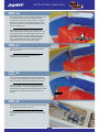
The wings slide into position over a carbon tube and are secured
in place with two plastic thumb screws. Take care not to trap the
servo leads when securing.
Schieben Sie die Tragflächen über das Karbonrohr und sichern
Sie diese mit den Kunststoffschrauben. Achten Sie darauf, dass
die Servokabel nicht eingeklemmt werden.
The battery is retained using a hook & loop strap. Each strap
is made by overlapping one end of each type by 30mm and run
some thin cyano in the joint. Then feed the straps through the
slots ready to secure the battery.
Befestigen Sie den Akku sorgfältig mit Klettband, wie rechts
gezeigt. Die Überlappung sollte min. 3cm betragen. Sichern Sie
das Band mit Sekundenkleber am Holzspant.
Drill and screw the cowling in position using two screws on each
side. Use masking tape to position and mark screw points. When
in position remove backplate spacers and attach the spinner.
Bohren und befestigen Sie die Motorhaube mit zwei Schrauben
auf jeder Seite. Nutzen Sie Maskierungsband, um die Bohrungen
anzuzeichnen. Montieren Sie anschließend den Spinner.
To set the cowl/spinner clearance, attach some foam tape to the
back of the back plate to act as a spacer. Position the cowl and
bolt on the spinner back plate to get the clearance correct.
Zum Einstellen des Abstandes der Motorhaube und des Spinners
befestigen Sie einige Schaumstoffbänder an der Rückseite
der Spinnerplatte. Diese dienen so als Abstandshalter für das
richtige Spaltmaß. Diese bitte am Ende wieder entfernen.
Seite wird geladen ...
Seite wird geladen ...
Seite wird geladen ...
Seite wird geladen ...
-
 1
1
-
 2
2
-
 3
3
-
 4
4
-
 5
5
-
 6
6
-
 7
7
-
 8
8
-
 9
9
-
 10
10
-
 11
11
-
 12
12
-
 13
13
-
 14
14
-
 15
15
-
 16
16
-
 17
17
-
 18
18
-
 19
19
-
 20
20
-
 21
21
-
 22
22
-
 23
23
-
 24
24


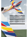
Ripmax Easy Street 2 Benutzerhandbuch
- Kategorie
- Ferngesteuertes Spielzeug
- Typ
- Benutzerhandbuch
in anderen Sprachen
- English: Ripmax Easy Street 2 User manual
Verwandte Artikel
-
Ripmax Phase 5 E Benutzerhandbuch
-
-
Ripmax WOT4-E Benutzerhandbuch
-
-
-
-
Ripmax A-CF010 Benutzerhandbuch
-
-
-
