
1 EN ML30 Instruction Manual DC Power Supply
2 DE ML30 Bedienungsanleitung DC Stromversorgung
3 FR ML30 Manual d'instructions DC Alimentation d'Énergie
4 ES ML30 Manual de instrucciones DC Fuente De Alimentación
5 IT ML30 Manuale di Istruzione DC Gruppo di alimentazione
6 PT ML30 Manual de Instruções DC Fonte De Alimentação
MiniLine
PSDR030W
ML30.241
012314
Read this first! English
1
Before operating this unit please read this manual thoroughly and retain this manual for future reference! This device may only be installed and put into operation by qualified personnel. If damage or
malfunction should occur during operation, immediately turn power off and send unit to the factory for inspection. The unit does not contain serviceable parts. The tripping of an internal fuse (if
included) is caused by an internal defect. The information presented in this document is believed to be accurate and reliable and may change without notice. For any clarifications the English
translation will be used.
Intended Use: This device is designed for installation in an enclosure and is intended for general use such as in industrial control, office, communication, and instrumentation equipment. Do not use
this device in equipment, where malfunction may cause severe personal injury or threaten human life.
WARNING
CAUTION
Risk of electrical shock, fire, personal injury or death.
1) Do not use the power supply without proper grounding (Protective Earth).
2) Turn power off before working on the device. Protect against inadvertent re-powering.
3) Make sure that the wiring is correct by following all local and national codes.
4) Do not modify or repair the unit.
5) Do not open the unit as high voltages are present inside.
6) Use caution to prevent any foreign objects from entering the housing.
7) Do not use in wet locations or in areas where moisture or condensation can be expected.
8) Do not touch during power-on, and immediately after power-off. Hot surfaces may cause burns.
Reduction of output current may be necessary when:
1) Minimum installation clearance can not be met.
2) Altitude is higher than 2000m.
3) Device is used above +60°C ambient.
4) Mounting orientation is other than the standard mounting orientation.
5) Airflow for convection cooling is obstructed.
Vor Inbetriebnahme lesen! Deutsch
2
Bitte lesen Sie diese Warnungen und Hinweise sorgfältig durch, bevor Sie das Gerät in Betrieb nehmen. Bewahren Sie die Anleitung zum Nachlesen auf. Das Gerät darf nur durch fachkundiges und
qualifiziertes Personal installiert werden. Bei Funktionsstörungen oder Beschädigungen schalten Sie sofort die Versorgungsspannung ab und senden das Gerät zur Überprüfung ins Werk. Das Gerät
beinhaltet keine Servicebauteile. Interne Sicherungen (falls vorhanden) lösen nur bei Gerätedefekt aus. Die angegebenen Daten dienen allein der Produktbeschreibung und sind nicht als
zugesicherte Eigenschaften im Rechtssinne aufzufassen. Im Zweifelsfall gilt der englische Text.
Bestimmungsgemäßer Gebrauch: Diese Gerät ist für den Einbau in ein Gehäuse konzipiert und zur Verwendung für allgemeine elektronische Geräte, wie z.B. Industriesteuerungen, Bürogeräte,
Kommunikationsgeräte oder Messgeräte geeignet. Benutzen Sie dieses Gerät nicht in Steuerungsanlagen, in denen eine Funktionsstörung zu schweren Verletzungen führen oder Lebensgefahr
bedeuten kann.
WARNUNG
VORSICHT
Missachtung nachfolgender Punkte kann einen elektrischen Schlag, Brände, schwere Unfälle oder Tod zur Folge
haben.
1) Betreiben Sie die Stromversorgung nie ohne Schutzleiter.
2) Schalten Sie die Eingangsspannung vor Installations-, Wartungs- oder Änderungsarbeiten ab und sichern Sie
diese gegen unbeabsichtigtes Wiedereinschalten.
3) Sorgen Sie für eine ordnungsgemäße und fachgerechte Verdrahtung.
4) Führen Sie keine Änderungen oder Reparaturversuche am Gerät durch.
5) Gerät niemals öffnen. Im Inneren befinden sich gefährliche Spannungen.
6) Verhindern Sie das Eindringen von Fremdkörpern, wie z.B. Büroklammern und Metallteilen.
7) Betreiben Sie das Gerät nicht in feuchter Umgebung oder in einer Umgebung mit Betauung
8) Gehäuse nicht während des Betriebes oder kurz nach dem Abschalten berühren. Heiße Oberflächen können
Verletzungen verursachen.
Rücknahme der Ausgangsleistung kann erforderlich sein:
1) Wenn die minimalen Einbauabstände nicht eingehalten werden können.
2) Bei Aufstellhöhen über 2000m.
3) Betrieb bei Umgebungstemperaturen über +60°C.
4) Bei Einbaulagen abweichend von der Standardeinbaulage.
5) Bei behinderter Luftzirkulation.
A lire avant mise sous tension! Français
3
Merci de lire ces instructions de montage et d'entretien avant de mettre l'alimentation sous tension. Conservez ce manuel qui vous sera toujours utile. Cette alimentation doit être installée par du
personnel qualifié et compétent. Le déclenchement du fusible interne traduit très probablement un défaut au niveau de l'appareil. Si un défaut quelconque apparaît en cours de fonctionnement,
débrancher au plus vite l'alimentation. Dans ce deux cas de figure, il convient de faire contrôler l'alimentation en usine! Les données indiquées dans ce document servent uniquement à donner une
description du produit et n'ont aucune valeur juridique. En cas de divergences, le texte anglais fait foi.
Utilisation: Cet appareil est conçu pour être installé dans une armoire et pour tous les équipements électroniques, tel que l'équipement industriel de commande, l'équipement de bureau, le matériel
de communication et les instruments de mesures. N'utilisez pas cet appareil sur des installations dans lesquels un problème de fonctionnement de l'alimentation pourrait causer des blessures graves
ou menacer la vie humaine.
AVERTISSEMENT
ATTENTION
Prendre en compte les points suivants, afin d'éviter toute détérioration électrique, incendie, dommage aux
personnes ou mort.
1) ne jamais faire fonctionner l'alimentation sans raccordement à la terre !
2) débrancher l'installation avant toute intervention sur l'alimentation (ou démontage) et s'assurer qu'il n'y a pas
risque de redémarrage
3) s'assurer que le câblage a été fait selon les prescriptions
4) ne pas effectuer de réparations ou modifications sur l'alimentation
5) ne pas ouvrir l'appareil. Des tensions importantes passent à l'intérieur
6) veiller à ce qu'aucun objet ne rentre en contact avec l'intérieur de l'alimentation (trombones, pièces
métalliques)
7) ne pas faire fonctionner l'appareil dans un environnement humide ou à l'extérieur, non protégé. Ne pas utiliser
l'appareil dans un environnement où il peut y avoir de la condensation
8) ne pas toucher le carter pendant le fonctionnement ou après la mise sous tension. Surface chaude risquant
d’entraîner des blessures
Des limitations de puissance de sortie peuvent apparaître si :
1) les distances d'installation mini. ne peuvent être observées
2) installation à une altitude > 2000m
3) pour des fonctionnements en charge et avec une température ambiante > 60°C
4) pour des positions de montage différentes de la préconisation standard
5) lorsque la circulation d'air est gênée
Seite wird geladen ...

ML30 Instruction Manual for Power Supplies
ML30 Bedienungsanleitung für Stromversorgung
Technical
Data
1)
Technische Daten
1)
PSDR030W / ML30.241
Output Voltage Ausgangsspannung nom.
DC 24-28V
Factory Setting at Full Load Werkseinstellung bei Nennlast typ.
Output Current
Ausgangsstrom nom.
Output P
ower Ausgangsleistung nom.
Output Ripple & Noi
se Voltage
2)
Ausgangswelligkeit
2
) max.
24.5
V
1.3A at
24V
1.1A at
28V
30W
50mVp
p
AC Input Voltage AC Eingangsspannung nom.
Input Frequen
cy Eingangsfrequenz
nom.
A
C Input Current
3)
AC Eingangsstrom
3)
ty
p.
P
ower Factor
3)
Leistungsfaktor
3)
ty
p.
DC Input Voltage
13)
DC Eingangsspannung
13)
min.
A
llowed Voltage L or N to Earth Erlaubte Spannung L oder N zu Erde max.
AC 100-240V
-15%/+10%
50-60Hz
0.54A / 0.3A
0.52 / 0.49
DC 110-300V
-20%/+25%
264Vac / 375Vdc
Input Inrush Current
4)
Einschaltspitzenstrom
4)
typ.
18A / 35A
Hold-up Time
3)
Pufferzeit
3)
typ.
31ms / 141ms
Efficiency
3)
Wirkungsgrad
3)
typ.
P
ower Losses
3)
Verlustleistung
3)
typ.
88.5% / 89.4%
4.1W / 3.7W
Operational Temperature Range Betriebstemperaturbereich nom.
Output Derating
Leistungsrücknahme +60°C to +7
0°C
Storage Tem
perature Range Lagertemperaturbereich nom.
-10°C - +70°C
0.8W/°C
-40°C - +85°C
Humidity
5)
Feuchte
5)
IEC 60068-2-30
5 - 95% r.H.
Vibration Schwingen IEC 60068-2-6
Shock
Schocken IEC 60068-2-27
2g
30g 6ms, 20g 11ms
Degree of Pollution (non-conductive) Verschmutzungsgrad (nicht leitend) EN 50178, IEC 62103
Degree of Prot
ection Schutzart EN 60529
Class of
Protection Schutzklasse IEC 61140
O
ver-temperature Protection Übertemperaturschutz OTP
Output
Over-voltage Protection Überspannungsschutz am Ausgang OVP, max.
2
IP20
I
6)
No
/ Nein
37Vdc
Leaka
ge Current
7)
TN/TT-mains PE- Ableitstrom
7)
TN/TT- Netze max.
IT-mains IT- Netze
Return
Voltage Resistance
8)
Rückspeisefestigkeit
8)
max.
0.3mA / 0.54mA
0.66mA / 1.08mA
35Vdc
Parallel Use
11)
Parallelschaltbar
11)
-
Seri
al Use
12)
Serienschaltbar
12)
-
Yes / Ja
Yes / Ja
Dimensions
9)
(WxHxD
) Abmessungen
9)
(BxHxT) nom.
W
eight Gewicht max.
22.5x75x91mm
140g / 0.31lb
Approvals Zulassungen -
10)
Limited Warranty Gewährleistung Years / Jahre
3
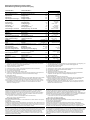
1) All parameters are specified at 230Vac input voltage, nominal output current, 25°C ambient
and after a 5 minutes run-in time unless otherwise noted.
2) 50-Ohm measurement, bandwidth 20MHz
3) at 120Vac, 60Hz / 230Vac 50Hz
4) Peak value at 120Vac / 230Vac, at an ambient temperature of 40°C and cold start.
5) Do not energize while condensation is present.
6) PE connection required (Ground).
7) Leakage current at 132Vac, 60Hz / 264Vac, 50Hz
8) Loads such as decelerating motors and inductors can feed voltage back to the output of the
power supply. The figure represents the maximum allowed feed back voltage
9) Depth without DIN-rail.
10) See datasheet or markings on the unit.
11) No current share between the units. Allowed up to 45°C ambient temperature. A fuse or diode
on the output of each unit is required if more than three units are connected in parallel.
12) Use only power supplies of the same type. The total output voltage should not be >150Vdc.
13) Use a battery or a similar DC source. Connect +pole to L and –pole to N. A supply from the
intermediate DC-bus of a frequency converter is not recommended and can cause a
malfunction or damage the unit.
1) Alle Werte gelten bei 230Vac Eingangsspannung, Nennausgangsstrom, 25°C Umgebung und
nach einer Aufwärmzeit von 5 Minuten, wenn nichts anderes angegeben ist.
2) 50-Ohm Messung, Bandbreite 20MHz
3) bei 120Vac, 60Hz / 230Vac, 50Hz
4) Spitzenstrom bei 120Vac / 230Vac, einer Umgebungstemperatur von 40°C und Kaltstart.
5) Nicht betreiben, solange das Gerät Kondensation aufweist.
6) PE Verbindung erforderlich.
7) Ableitstrom bei 132Vac, 60Hz / 264Vac, 50Hz
8) Bremsende Motoren oder Induktivitäten können Spannung zum Ausgang des Netzteils
rückspeisen. Der Wert gibt die max. zulässige Rückspeisespannung an.
9) Tiefe ohne DIN-Schiene
10) Siehe Datenblatt oder Prüfzeichen auf dem Gerät.
11) Keine Stromaufteilung zwischen den Geräten. Erlaubt bis max. 45°C. Eine Sicherung oder
Diode je Ausgang ist erforderlich wenn mehr als 3 Geräte parallel geschaltet werden.
12) Nur gleiche Geräte bis zu einer Gesamtspannung von 150Vdc
13) Geeignet sind Batterien oder ähnliche Quellen. Den +Pol an L und –Pol an N anschließen.
Ein Betrieb am Zwischenkreis von Frequenzumrichtern wird nicht empfohlen und kann zu
Defekten oder Fehlfunktionen führen.
Installation
Use DIN-rails according to EN 60715 or EN 50022 with a height of 7.5 or 15mm. Mounting
orientation must be output terminals on top and input terminals on the bottom. For other
orientations see datasheet. Do not obstruct air flow as the unit is convection cooled. Ventilation
grid must be kept free of any obstructions. The following installation clearances must be kept
when power supplies are permanently fully loaded:
Left / right: 0mm (or 15mm in case the adjacent device is a heat source)
40mm on top, 20mm on the bottom of the unit.
Use in hazardous location areas
Units which are marked with "Class I Div 2" are suitable for use in Class I Division 2 Groups A, B,
C, D locations.
WARNING EXPLOSION HAZARDS!
Substitution of components may impair suitability for this environment. Do not disconnect the unit
or operate the voltage adjustment unless power has been switched off or the area is known to be
non-hazardous. A suitable enclosure must be provided for the end product which has a minimum
protection of IP54 and fulfils the requirements of the EN 60079-15:2010.
Input Fuses
Internal input fuse included, not user accessible. The unit is tested and approved for branch circuits
up to 20A. An external protection is only required if the supplying branch has an ampacity greater
than this, however, in some countries local regulations might apply. Check local codes and
requirements. If an external fuse is necessary or utilized, minimum requirements need to be
considered to avoid nuisance tripping of the circuit breaker. A minimum value of 6A B- or 3A C-
Characteristic breaker should be used.
Installation
Geeignet für DIN-Schienen entsprechend EN 60715 oder EN 50022 mit einer Höhe von 7,5 oder
15mm. Der Einbau hat so zu erfolgen, dass sich die Eingangsklemmen unten und die
Ausgangsklemmen oben befinden. Für andere Einbaulagen siehe Datenblatt. Luftzirkulation nicht
behindern! Das Gerät ist für Konvektionskühlung ausgelegt. Es ist für ungehinderte Luftzirkulation
zu sorgen. Folgende Einbauabstände sind bei dauerhafter Volllast einzuhalten:
Links / rechts: 0mm (oder 15mm bei benachbarten Wärmequellen)
Oben: 40mm, unten 20mm vom Gerät.
Betrieb in explosionsgefährdeter Umgebung
Geräte, die mit "Class I Div 2" gekennzeichnet sind, sind für den Einsatz in Klasse I Division 2
Gruppen A,B,C,D Umgebung geeignet.
ACHTUNG EXPLOSIONSGEFAHR!
Veränderungen am Gerät können die Tauglichkeit für diese Umgebung beeinträchtigen.
Anschlüsse nicht abklemmen und Spannungseinstellung nicht verändern, solange Spannung
anliegt oder die Umgebung als explosionsgefährlich gilt. Das Gerät muss mindestens in ein IP54
Gehäuse, welches den Anforderungen der EN 60079-15:2010 entspricht, eingebaut werden.
Sicherungen am Eingang
Das Gerät besitzt eine Eingangssicherung, die nicht anwenderzugänglich ist. Das Gerät ist geprüft
und zugelassen zum Anschluss an Stromkreisen bis max. 20A. Ein zusätzlicher externer Schutz
ist nur erforderlich, wenn der Speisestromkreis mit einem höheren Wert abgesichert ist oder
nationale Richtlinien es vorschreiben. Falls ein externes Schutzelement verwendet wird, soll
dieses nicht kleiner als 6A B- oder 3A C-Charakteristik sein, um ein fehlerhaftes Auslösen zu
vermeiden.

ML30 Instruction Manual for Power Supplies
ML30 Bedienungsanleitung für Stromversorgung
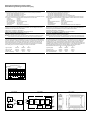
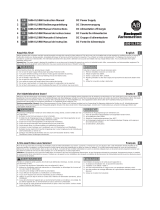
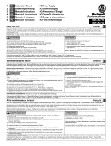
Fig. 4 / Bild 4
ML30.241: Output Characteristic /
Ausgangskennlinie, typ
Output Voltage
Adjustment
Range
28V
24
20
16
12
8
4
Output Current
0
0 0.4 0.8 1.2 1.6 2.0 2.4
2.8A
Terminals and Wiring
Use appropriate copper cables that are designed for a minimum operating temperature of:
60°C for ambient temperatures up to 45°C,
75°C for ambient temperatures up to 60°C and
90°C for ambient temperatures up to 70°C.
Follow national installation codes and regulations! Ensure that all strands of a stranded wire enter
the terminal connection! Ferrules are allowed. Unused terminal must be closed.
Solid wire 0.5-6mm
2
Stranded wire 0.5-4mm
2
American wire gauge AWG20-10
Max. wire diameter: 2.8mm (includes ferrules)
Wire stripping length 7mm / 0.28inch
Tightening torque 1Nm / 9lb.inch
Screw driver: 3.5mm slotted or Philips No 2
CE Marking
CE mark is in conformance with EMC directive 2004/108/EC, the low-voltage directive (LVD)
2006/95/EC and the RoHS directive 2011/65/EU.
EMC Immunity: EN 61000-6-1, EN 61000-6-2
EMC Emission EN 61000-6-3, EN 61000-6-4, FCC Part 15 Class B
Output- and Overload Characteristic (see Fig. 4)
The units are overload, no-load, short-circuit proof.
ML30: Above the rated output current, the output voltage will decrease as a result of the output
current limitation. The current flows continuously. No hiccup or shut-down behaviour.
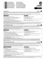
Dielectric Strength (see Fig. 5)
The output voltage is floating and separated from the input according to SELV (IEC/EN 60950-1)
and PELV (EN 60204-1, EN 50178; IEC 62103, IEC 60364-4-41) requirements. Type and factory
tests are conducted by the manufacturer. Field tests may be conducted in the field using the
appropriate test equipment which applies the voltage with a slow ramp (2s up and 2s down).
Connect all phase-terminals together as well as all output poles before the test is conducted.
When testing, set the cut-off current settings to the value in the table below.
A B
C
Type Test (60s) 2500Vac 3000Vac 500Vac
Factory Test (5s) 2500Vac 2500Vac 500Vac
Field Test (5s) 2000Vac 2000Vac 500Vac
Cut-off current setting
>6mA
>6mA
>1mA
Anschlussklemmen und Verdrahtung
Verwenden Sie geeignete Kupferkabel, die mindestens für:
60°C bei einer Umgebungstemperatur bis zu 45°C,
75°C bei einer Umgebungstemperatur bis zu 60°C und
90°C bei einer Umgebungstemperatur bis zu 70°C zugelassen sind.
Aderendhülsen sind erlaubt. Nationale Bestimmungen und Installationsvorschriften beachten!
Achten, dass keine einzelnen Drähte von Litzen abstehen. Nichtbenutzte Klemmen schließen.
Starrdraht 0,5-6mm
2
Litze 0,5-4mm
2
AWG AWG20-10
Maximaler Drahtdurchmesser: 2,8mm (incl. Aderendhülsen)
Abisolierlänge 7mm / 0,28inch
Anzugsdrehmoment
1Nm / 9lb.inch
Schraubendreher: Schlitzschraubendreher 3,5mm oder Philips No 2
CE Kennzeichnung
Das CE Zeichen ist angebracht und erklärt die Erfüllung der EMV Richtlinie 2004/108/EG, der
Niederspannungsrichtlinie 2006/95/EG und der RoHS Richtlinie 2011/65/EU.
Störfestigkeit: EN 61000-6-1, EN 61000-6-2
Störaussendung: EN 61000-6-3, EN 61000-6-4, FCC Part 15 Klasse B
Ausgangs- und Überlastverhalten (siehe Bild 4)
Die Geräte sind leerlauf-, überlast- und kurzschlussfest.
ML30: Wird der Nennstrom überschritten, sinkt die Spannung aufgrund der Strombegrenzungs-
eigenschaft. Der Strom fließt ununterbrochen weiter, kein Hiccup oder Abschaltverhalten.
Isolationsfestigkeit (siehe Bild 5)
Die Ausgangsspannung hat keinen Bezug zur Erde oder Schutzleiter und ist zum Eingang nach
den SELV (IEC/EN 60950-1) und PELV (EN 60204-1, EN 50178, IEC 62103, IEC 60364-4-41)
Standards getrennt. Typ- und Stückprüfungen werden beim Hersteller durchgeführt. Wieder-
holungsprüfungen dürfen mittels geeigneten Prüfgenerators mit langsam (2s) ansteigenden und
abfallenden Spannungsrampen in der Anwendung erfolgen. Vor den Tests sind alle Phasen wie
auch alle Ausgangspole miteinander zu verbinden. Während der Tests darf die Strom-
Abschaltschwelle nicht kleiner als der in der Liste angegebene Wert sein.
A B C
Typprüfung (60s) 2500Vac 3000Vac 500Vac
Stückprüfung (5s) 2500Vac 2500Vac 500Vac
Wiederholungsprüfung (5s) 2000Vac 2000Vac 500Vac
Strom- Abschaltschwelle
>6mA
>6mA
>1mA
Fig. 5 / Bild 5
Insulation / Isolation
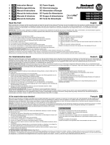
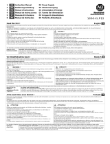
Fig. 6 / Bild 6
Functional Diagram / Funktionsschaltbild
Fig. 7 / Bild 7
Physical Dimensions / Abmessungen
Input
L
N
A
Earth, PE
Output
+
-
L
Input Fuse
N
&
Input Filter
PE
Input
Rectifier
&
Inrush
Limiter
Power
Converter
DC
on
+
Output
Filter
-
-
Output Over-
Voltage
Protection
Output
Voltage
Regulator
V
OUT
-
 1
1
-
 2
2
-
 3
3
-
 4
4


Redlion MiniLine PSDR030W Benutzerhandbuch
- Typ
- Benutzerhandbuch
- Dieses Handbuch eignet sich auch für
in anderen Sprachen
- English: Redlion MiniLine PSDR030W User manual
- français: Redlion MiniLine PSDR030W Manuel utilisateur
- español: Redlion MiniLine PSDR030W Manual de usuario
- italiano: Redlion MiniLine PSDR030W Manuale utente
Andere Dokumente
-
 Rockwell Automation 1606-XLS120E Benutzerhandbuch
-
IFM AC1212 Installationsanleitung
-
 Rockwell Automation 1606-XLS960 Benutzerhandbuch
-
 Rockwell Automation 1606-XLS480 Benutzerhandbuch
-
 Rockwell Automation 1606-XLS240 Benutzerhandbuch
-
 Rockwell Automation 1606-XLEDNET3 Benutzerhandbuch
-
Puls ML70.100 Benutzerhandbuch
-
 Rockwell Automation 1606-xlp15 Benutzerhandbuch
-
 Rockwell Automation 1606-xlp15 Benutzerhandbuch
-
Dometic Mobicool ML30, ML40 Bedienungsanleitung


