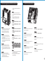
Thermaltake Element V NVIDIA Edition Basic Benutzerhandbuch
- Kategorie
- Computergehäuse
- Typ
- Benutzerhandbuch
Seite laden ...
Seite laden ...

3 4
1.1 Please Read First
English /
Thermaltake Element V NVIDIA Edition is designed to maximize heat dissipation when configuring
the NVIDIA GeForce GTX 470 / 480 graphic cards in 3-Way or Quad SLI. Included fan duct
system and high-RPM fan are provided to accelerate cool air delivery ensuring proper thermal
management. Users with any other configuration will still benefit from Element V's stock fan
configuration which delivers most efficient airflow in its class without having to install the optional
fan duct system and high-RPM fan.
Please take great care when handling the high-RPM fan while it is powered on as it may cause
serious injury.
繁體中文 /
Thermaltake Element V NVIDIA Edition 機箱旨在提供最佳散熱方案,適用於 3-Way 或 Quad SLI 下
的 NVIDIA GeForce GTX 470/480 顯示卡配置。產品配備風扇導風罩系統和高轉速風扇,通過加速冷
卻風來確保適當的散熱管理。Element V 的原裝風扇還能為其他配置的使用者帶來好處,風扇可產生高
效的冷卻氣流,而無需安裝額外的風扇導風罩系統和高轉速風扇。
在高轉速風扇通電的狀態下處理風扇可能會導致嚴重受傷,因此請務必謹慎作業。
Deutsch /
Die Thermaltake Element V NVIDIA Edition wurde entwickelt, um die Wärmeableitung bei der
Konfiguration der NVIDIA GeForce GTX 470/480 Grafikkarten in 3-Wege oder Quad-SLI zu
maximieren. Das mitgelieferte Lüfterkanalsystem und der hochdrehzahlige Ventilator
beschleunigen die Verteilung der Kühlluft, um ein ordnungsgemäßes thermisches Management zu
gewährleisten. Benutzer mit anderen Konfigurationen werden auch von der Element V Ventilator-
Konfiguration profitieren, die den effizientesten Luftstrom in ihrer Klasse bietet, ohne ein
optionales Lüfterkanalsystem und einen hochdrehzahligen Ventilator zu installieren.
Bitte gehen Sie beim Umgang mit dem eingeschalteten hochdrehzahligen Ventilator mit großer
Sorgfalt vor, da eine Berührung zu schweren Verletzungen führen kann.
Français /
L'Élément V NVIDIA Édition de Thermaltake est conçu pour optimiser la dissipation de chaleur lors
de la configuration des cartes graphiques NVIDIA GeForce GTX 470/480 en 3-Way ou Quad SLI.
Le système de tunnel de ventilation inclus et le ventilateur à grande vitesse sont fournis pour
accélérer la distribution d'air frais et garantir une bonne gestion thermique. Les utilisateurs
possédant une autre configuration pourront toujours profiter de la configuration de ventilation de
base de l'Elément V qui fournit le flux d'air le plus efficace de sa classe sans devoir installer le
système de tunnel de ventilation et le ventilateur à grande vitesse facultatifs.
Veuillez faire très attention en manipulant le ventilateur à grande vitesse lorsqu'il est en marche
car il peut causer de graves blessures.
Español /
Thermaltake Element V NVIDIA Edition está diseñado para maximizar la disipación del calor al
configurar las tarjetas gráficas NVIDIA GeForce GTX 470 / 480 en SLI de 3 vías o cuádruple. El
sistema de conducto de ventilación y el ventilador de RPM alto sirven para acelerar el suministro
de aire frío para garantizar una adecuada gestión térmica. Los usuarios con cualquier otra
configuración se benefician de la configuración del ventilador de reserva de Element V que
suministra el flujo de aire más eficiente de su clase sin tener que instalar el sistema de conducto
de ventilador opcional ni el ventilador de RPM alto.
Tenga cuidado cuando manipule el ventilador de RPM alto mientras esté encendido ya que puede
causar lesiones serias.
Italiano /
Thermaltake Element V NVIDIA Edition è progettato per ottimizzare la dissipazione di calore
durante la confugurazione delle schede grafiche NVIDIA GeForce GTX 470 / 480 in SLI 3-Way o
Quad. Inclusi sono forniti il sistema di ventilazione in condotta e la ventola con RPM elevato per
accelerare la distribuzione di aria fredda garantendo un'appropriata gestione delle condizioni
termiche. Anche gli utenti con altre configurazioni potranno beneficiare della configurazione della
ventola della serie Element V che fornire il più efficiente flusso d’aria della classe senza richiedere
l’installazione del sistema di ventilazione a condotta opzionale e della ventola a RPM elevato.
Prestare particolare attenzione quando si maneggia la ventola a RPM elevato durante la relativa
alimentazione per evitare gravi lesioni.
简体中文
/
简体中文
/Thermaltake Element V NVIDIA Edition 机箱采用了最大化散热设计方案,适用于 3-Way 或 Quad
SLI 下的 NVIDIA GeForce GTX 470 / 480 显卡配置。产品配有风扇导风罩系统和高转速风扇,以通
过加速冷却风来确保适当的散热管理。Element V 的原装风扇也可让使用其它配置的用户获益,无需安
装额外的风扇导风罩系统和高转速风扇即能产生高效的冷却气流。
鉴于在通电状态下处理高转速风扇可能会导致严重人身伤害,请务必谨慎操作。
日本語 /日本語 /
Thermaltake Element V NVIDIA Editionは3-WayまたはQuad SLIでNVIDIA GeForce GTX 470 /
480グラフィックカードを設定しているとき、最大の熱放散が得られるように設計されています。組
み込み型のファンダクトシステムと高RPMファンは、冷気の流れを加速して適切な温度管理を確実
に行います。他のシステムをお使いのユーザーの方でも、Element Vのストックファン設定を最大限
に活用することができます。この設定では、オプションのファンダクトシステムと高RPMファンを
取り付けずにクラス最高の効率的な空気の流れを達成できます。
電源がオンになっているときに高RPMファンを処理するときは十分に注意してください。重傷を負
う可能性があります。
Русский /Русский /
Корпус Thermaltake Element V NVIDIA предназначен для увеличения теплоотвода в
конфигурациях с технологиями 3-Way или Quad SLI на основе графических плат
NVIDIA GeForce GTX 470/480. Встроенная система воздуховодов вентилятора и
вентилятор с высокой скоростью вращения обеспечивают быструю подачу холодного
воздуха и надлежащее теплорегулирование. Конфигурация базового вентилятора в
корпусе Element V также идеально подходит для любой другой конфигурации
оборудования. Корпус обеспечивает наиболее эффективный в своем классе поток
воздуха без необходимости установки дополнительной системы воздуховодов
вентилятора и вентилятора с высокой скоростью вращения.
Будьте предельно осторожны при обращении с включенным вентилятором с высокой
скоростью вращения, поскольку он может причинить серьезную травму.
Türkçe /
Thermaltake Element V NVIDIA Edition, 3 Yönlü veya Dörtlü SLI ana kartlardaki NVIDIA GeForce
GTX 470 / 480 grafik kartlarını yapılandırırken ısı dağılımını en üst düzeye çıkaracak şekilde
tasarlanmıştır. Ürüne dahil olan fan kanalı sistemi ve yüksek devirli fan, termal yönetimin doğru bir
şekilde yapılabilmesi için soğuk hava dağıtımını hızlandırmak amacıyla sağlanmaktadır. Diğer
yapılandırmalara sahip kullanıcılar, isteğe bağlı fan kanalı sistemini ve yüksek devirli fanı takmaya
gerek kalmadan sınıfının en verimli hava akışını sağlayan Element V stok fan yapılandırmasından
yararlanmaya devam edebilecektir.
Yüksek devirli fanı tutarken lütfen çok dikkatli olun. Bu fan, açıkken ciddi yaralanmalara neden
olabilir.

5 6
1.2 CPU Cooler Height & VGA (Add-on card) Length Limitation
Warning!!
Warnung!!
Avertissement !
Precaución
CPU Cooler Height Limitation:
Please ensure that your CPU cooler does NOT exceed 165mm (6.5 inches) height.
VGA (Add-on card) Length Limitation:
Please ensure that your VGA (Add-on card) does NOT exceed 335mm (13.2 inches) length.
警告!!
CPU 冷卻器的高度限制:
請確保 CPU 冷卻器的高度不超過 165 mm (6.5 英吋)。
VGA (附加介面卡) 的長度限制:
請確保 VGA (附加介面卡) 的長度不超過 335 mm (13.2 英吋)。
警告!!
CPU 散热器高度限制:
请确保 CPU 散热器的高度不超过 165 mm(6.5 英寸)。
VGA(附加卡)长度限制:
请确保 VGA(附加卡)的长度不超过 335 mm(13.2 英寸)。
警告
CPUクーラーの高さ制限:
CPUクーラーの高さが165mmを超えていないことを確認してください。
VGA(アドオンカード)の長さ制限:
VGA(アドオンカード)の長さが335mmを超えていないことを確認してください。
CPU-Kühler Höhenbeschränkung:
Bitte stellen Sie sicher, dass Ihr CPU-Kühler 165 mm (6,5 Zoll) Höhe nicht überschreitet.
VGA (Add-on-Karte) Längenbeschränkung:
Bitte stellen Sie sicher, dass Ihre VGA (Add-on-Karte) 335 mm (13,2 Zoll) Länge nicht
überschreitet.
Limite de hauteur du ventilateur de CPU :
Vérifiez que la hauteur du ventilateur de CPU ne dépasse pas 165 mm.
Limite de longueur de la carte (complémentaire) VGA :
Vérifiez que la longueur de votre carte (complémentaire) VGA ne dépasse pas 335 mm
Limitación de altura del refrigerador de CPU:
Asegúrese de que la altura de su refrigerador de CPU no excede los 165 mm (6,5 pulgadas).
Limitación de longitud de la tarjeta de vídeo (adicional):
Asegúrese de que la longitud de su tarjeta de vídeo (adicional) no excede los 335 mm (6,2
pulgadas).
Внимание!
Ограничение по высоте охладителя ЦП
Убедитесь, что высота охладителя ЦП (центрального процессора) НЕ превышает 165 мм
(6,5 дюйма).
Ограничение по длине видеокарты VGA (плата расширения)
Убедитесь, что длина видеокарты VGA (плата расширения) НЕ превышает 335 мм (13,2 дюйма).
Attenzione!
Limitazione altezza dissipatore CPU:
Assicurarsi che l’altezza del dissipatore CPU NON superi 165 mm (6,5 pollici).
Limitazione lunghezza VGA (scheda aggiuntiva):
Assicurarsi che la lunghezza del VGA (scheda aggiuntiva) NON superi 335 mm (13,2 pollici).
Uyarı!!
CPU Soğutucu Yükseklik Sınırlaması:
Lütfen CPU soğutucunuzun yüksekliğinin 165mm’yi (6,5 inç) GEÇMEDİĞİNDEN emin olun.
VGA (Eklenti kartı) Uzunluk Sınırlaması:
Lütfen VGA’nızın (Eklenti kartı) uzunluğunun 335mm’yi (13,2 inç) GEÇMEDİĞİNDEN
emin olun.
<165 mm
<335 mm

7
8
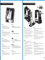
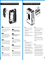
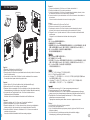
2.0 Side Panels Disassembly
English /
1. To remove the left-hand side panel,
please remove thumb screws on the
back of the case.
2. Push the buttons, then pull out the side
panel.
3. To remove the right-hand side panel,
please remove screws on the back of
the case.
4. Pull out the right-hand side panel as
arrow shows.
Deutsch /
1. Um die Seitentafel auf der linken Seite
zu entfernen, beseitigen Sie die
Flügelschrauben auf der Rückseite des
Gehäuses.
2. Drücken Sie auf die Knöpfe und ziehen
Sie die Seitentafel heraus.
3. Um die Seitentafel auf der rechten Seite
zu entfernen, beseitigen Sie die
Flügelschrauben auf der Rückseite des
Gehäuses.
4. Ziehen Sie die Seitentafel auf der
rechten Seite entsprechend den Pfeilen
heraus.
Français /
1. Pour enlevez le panneau latéral gauche,
s'il vous plaît dévissez les vis au dos du
boîtier.
2. Appuyez sur les boutons, puis tirez le
panneau latéral.
3. Pour enlever le panneau latéral droit,s'il
vous plaît dévissez les vis au dos du
boîtier.
4. Tirez le panneau latéral de droite
comme la flèche l'indique.
Español /
1. Para extraer el panel lateral izquierdo,
extraiga los tornillos de mano de la parte
trasera de la caja.
2. Empuje los botones y a continuación tire
del panel lateral hacia afuera.
3. Para extraer el panel lateral izquierdo,
extraiga los tornillos de la parte trasera
de la caja.
4. Tire del panel lateral derecho hacia
fuera cómo indica la flecha.
Italiano /
1. Per rimuovere il pannello laterale di
sinistra, rimuovere le viti ad aletta nella
parte posteriore del case.
2. Premere i pulsanti, quindi estrarre il
pannello laterale.
3. Per rimuovere il pannello laterale di
destra, rimuovere le viti nella parte
posteriore del case.
4. Tirare il pannello laterale di destra come
indicato dalla freccia.
繁體中文 /
1. 若要拆下左側面板,請先拆下機殼背面的蝶形
螺絲。
2. 按下按鍵,然後拉出側面板。
3. 若要拆下右側面板,請先拆下機殼背面的螺絲。
4. 如箭頭所示拉出右側面板。
简体中文 /简体中文 /
1. 若要卸下左侧面板,请先卸下机壳背面的蝶形
螺丝。
2. 按下按钮,然後拉出侧面板。
3. 若要卸下右侧面板,请先卸下机壳背面的螺
丝。
4. 如箭头所示拉出右侧面板。
日本語 /日本語 /
1. 左側の側面パネルを取り外すには、ケース背
面の蝶ねじを外してください。
2. ボタンを押して、側面パネルを取り外しま
す。
3. 右側の側面パネルを取り外すには、ケース背
面のねじを外してください。
4. 矢印で示すように、右側のパネルを取り外し
ます。
Русский /Русский /
1. Чтобы снять левую часть панели,отви
нтите винт с головкой на задней част
и корпуса.
2. Нажмите на кнопки, затем потяните и
снимите боковую панель.
3. Чтобы снять правую боковую панель,
извлеките верхний и нижний винты в
задней части корпуса.
4. Потяните правую часть панели в нап
равлении, указанном стрелками на ри
сунке.
Türkçe /
1. Sol taraftaki yan paneli çıkarmak
için,lütfen kasanın arkasındaki silindirik
başlı ayar cıvatalarını çıkarın.
2. Düğmeleri bastırın ve yan paneli
çekerek çıkarın.
3. Sağ taraftaki yan paneli çıkarmak için,
lütfen kasanın arkasındaki vidaları çıkarı
n.
4. Sağ taraftaki yan paneli okla gösterilen
yönde çekerek çıkarın.
1
2
3
4

9 10
2.1 Motherboard Installation
English /
1. Lay down the chassis.
2. Install the motherboard in proper
location and secure it with screws.
Deutsch /
1. Legen Sie das Gehäuse auf die Seite.
2. Installieren Sie die Hauptplatine in ihrer
vorgesehenen Position und sichern Sie
sie mit Schrauben.
Français /
1. Posez à plat le châssis.
2. Installez la carte mère dans l’endroit
approprié et sécurisez-la avec des vis.
Español /
1. Tumbe el chasis.
2. Instale la placa madre en la ubicación
adecuada y asegúrela con tornillos.
Italiano /
1. Poggiare lo chassis.
2. Installare la scheda madre nella
posizione appropriata e fissarla con le
viti.
繁體中文 /
1. 放平機殼。
2. 將主機板安裝在適當位置,然後用螺絲固定。
日本語 /日本語 /
. シャーシを下に置きます。
2. マザーボードを適切な場所に取り付け、ねじ
で固定します。
1
Русский /Русский /
1. Раскройте системный блок.
2. Установите материнскую плату в надлеж
ащее место и закрепите ее винтами.
简体中文 /简体中文 /
1. 放平机箱。
2. 将主板安装到正确位置并以螺丝固定。
Türkçe /
1. Kasayı yan yatırın.
2. Ana kartı uygun konuma takın ve vidalarla
sabitleyin.
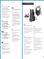
2.2 5.25” Drives Installation
English /
1. Pull the bottom of the front panel to
detach it from the chassis.
2. Remove the 5.25" drive bay plastic cover.
3. Push inward and upward to unlock the
tool-free clip on 5.25” HDD cage.
4. Insert the 5.25” device into the driver bay
and push inward and downward to lock
the tool-free clip.
Deutsch /
1. Ziehen Sie am unteren Rand der
Vorderseitentafel, um sie vom Gehäuse
zu entfernen.
2. Entfernen Sie die Plastikabdeckung des
5,25 Zoll Schachts.
3. Drücken Sie einwärts und aufwärts, um
den Clip ohne Werkzeug auf dem 5,25
Zoll HDD-Käfig zu entsperren.
4. Führen Sie die 5,25 Zoll Einheit in den
Schacht ein und drücken Sie einwärts und
abwärts, um den werkzeuglosen Clip zu
befestigen.
Français /
1. Tirez sur le bas du panneau avant pour le
démonter du châssis.
2. Retirez le couvercle en plastique de la baie 5.25"
3. Poussez vers l’intérieur et vers le haut pour
déverrouiller le clip sans outil sur la cage à
disque dur 5.25”
4. Insérez le périphérique 5.25” dans la baie pour
lecteur et poussez vers l’intérieur et vers le bas
pour verrouiller le clip sans outil.
Español /
1. Tire de la parte inferior del panel frontal para
separarlo del chasis.
2. Extraiga la cubierta de plástico de la bahía de
unidad de 5,25 pulgadas.
3. Empuje hacia dentro y hacia arriba para abrir el
sujetador sin herramientas del cajón del HDD de
5,25 pulgadas.
4. Inserte el dispositivo de 5,25 pulgadas en la bahía
de unidad y empuje hacia dentro y hacia abajo para
cerrar el sujetador sin herramientas.
1
2
4
3

11
12
简体中文 /
日本語 /
Русский /
Italiano /
1. Tirare il pulsante del pannello anteriore
Русский /
per sganciarlo dallo chassis.
1. Потяните за нижнюю часть передней
2. Rimuovere il coperchio in plastica
панели, чтобы отсоединить ее от кор
dell’alloggiamento dell’unità da 5,25”.
пуса.
3. Spingere all’interno e verso l’alto per
2. Снимите пластмассовую заглушку
sboccare la clip tool-free nel
отсека 5,25-дюймового дисковода.
contenitore HDD da 5,25”.
3. Для разблокировки фиксатора, не
4. Inserire il dispositivo da 5,25” nel vano
требующего применения инструмент
unità e spingere verso l’interno e in
ов, на каркасе для 5,25-дюймовых же
basso per bloccare la clip tool-free.
стких дисков нажмите на каркас и
приподнимите его.
繁體中文 / 4. Вставьте 5,25-дюймовое устройство
1. 拉面板底部,將面板從底盤拆下。
в отсек дисководов и нажмите на отс
ек и опустите его для блокировки фи
2. 拆下 5.25" 磁碟機槽的塑膠蓋。
ксатора, не требующего применения
3. 向內部的上方壓下,以解除鎖定 5.25"
инструментов.
硬碟盒上的免用工具扣具。
4. 將 5.25" 磁碟機插入磁碟機槽,向內部
的下方壓下以鎖定免用工具扣具。
Türkçe /
1. Ön paneli alt kısmından çekerek asadan
ayırın.
简体中文 /
2. 5.25” sürücü bölmesinin plastik
1. 拉面板底部,将其从底板卸下。
kapağını çıkarın.
2. 卸下 5.25” 驱动器槽的塑料盖。
3. 5.25” HDD kafesindeki araçsız
3. 向内部上方压 5.25” 硬盘盒上的免用工具
kelepçenin kilidini içeri ve yukarı doğru
扣具,以将其解除锁定。
iterek açın.
4. 将 5.25” 设备插入驱动器槽中,并向内部
4. 5.25” aygıtını sürücü bölmesine
下方压免用工具扣具以将其锁定。
yerleştirin ve araçsız kelepçeyi içeri ve
aşağı doğru iterek kilitleyin.
日本語 /
1. フロントパネルの下部を引っ張って、
シャーシから取り外します。
2. 5.25”ドライブベイのプラスチックカバ
ーを取り外します。
3. 内側および外側に押して5.25” HDDケー
ジの工具不要クリップをアンロックしま
す。
4. 5.25”デバイスをドライブベイに差し込
み、上下に押して工具不要クリップをロ
ックします。
2.3 3.5” HDD Installation
English /
1. Squeeze and pull out-ward the tool-free
clip.
2. Insert HDD by sliding HDD into the icage.
3. Secure HDD by tightening screw to HDD.
4. Squeeze and push in-ward the tool free
clip to secure the icage.
Deutsch /
1. Drücken Sie die Klemme von Hand (kein
Werkzeug erforderlich) zusammen,
ziehen Sie sie heraus.
2. Setzen Sie eine Festplatte ein, indem Sie
sie in den iCage-Festplattenkäfig
schieben.
3. Sichern Sie die Festplatte durch
Festdrehen der Schraube.
4. Drücken Sie die Klemme von Hand (kein
Werkzeug erforderlich) zusammen,
schieben Sie sie zur Befestigung des
iCage-Festplattenkäfigs hinein.
Français /
1. Appuyer pour extraire le clip sans outil.
2. Insérer le HDD en le glissant dans l'iCage.
3. Fixer le HDD en serrant la vis.
4. pour fixer l'iCage, presser et insérer le clip-
sans-outil .
Español /
1. Presione por los extremos y tire hacia fuera
de la fijación sin herramientas.
2. Inserte el HDD deslizando la unidad HDD
hacia dentro en la carcasa iCage.
3. Fije la unidad HDD enroscando los tornillos
en la unidad HDD.
4. Presione por los extremos y empuje hacia
dentro el clip libre de herramientas para fijar
la carcasa iCage.
4
2
3
1
Seite laden ...

15
16
简体中文 /
日本語 /
Русский /
Italiano /
繁體中文 /
English /
简体中文 /
Deutsch /
日本語 /
Русский /
1. Установите блок питания в надлежа
Français /
щее место и закрепите его винтами.
1.
2. Отрегулируйте расположение блока
питания и закрепите его с помощью
винта.
Türkçe /
Español /
1.
ubicación adecuada y asegúrela con
tornillos.
1. Installare l'unità dell’alimentatore in
modo appropriato e fissarla utilizzando
le viti.
2. Regolare la PSU nella posizione
appropriata e fissarla con la vite.
1. 將電源供應器安裝在適當位置,然後用螺
絲固定。
2. 將 PSU 穩定調整至適當位置,然後用螺
絲固定。
1. Install the power supply unit in proper
1. 将电源供应器单元安装至正确位置并以螺
location and secure it with screws.
丝固定。
2. Adjust the PSU steady to proper
2. 将电源供应器单元稳定调整至正确位置并
location and secure it with screw.
以螺丝固定。
1. Installieren Sie das Netzteil an der
1. 電源装置を適切な場所に取り付け、ねじで
richtigen Position und sichern Sie es
固定します。
mit Schrauben.
2. PSUを適切な場所に調整し、ねじで締め付
2. Richten Sie das Netzteil ordentlich an
けます。
seiner Position aus und sichern Sie es
mit Schrauben.
Mettez l’alimentation dans le bon
endroit et sécurisez-la avec des vis.
2. Fixez le bloc alimentation dans le bon
emplacement et securisez-le avec des
vis.
1. Güç kaynağı birimini uygun konuma takı
n ve vidalarla sabitleyin.
Instale la unidad de fuente de
2. PSU’yu uygun konuma ayarlayın ve
alimentación en el lugar adecuado y
vidayla sabitleyin.
asegúrela con tornillos.
2. Ajuste la PSU estabilizada en la
2.5 Power Supply Unit (PSU) Installation
2.6 PCI Card Installation
简体中文 /
日本語 /
Русский /
English /
繁體中文 /
简体中文 /
Deutsch /
日本語 /
Français /
Русский /
Español /
Türkçe /
Italiano /
Insert the PCI card into the PCI slot, and
將 PCI 卡插入 PCI 插槽,然後用螺絲固定。
secure it with screw.
将 PCI 卡插入 PCI 插槽并以螺丝固定。
Stecken Sie die PCI Karte in den PCI
Steckplatz und sichern Sie sie mit
Schrauben.
PCI カードを PCI スロットに挿入し、ねじで
固定します。
Insérez la carte PCI dans le slot PCI et
sécurisez-la avec des vis.
Вставьте PCI-карту в слот PCI и закреп
ите ее винтом.
Inserte la tarjeta PCI en la ranura del PCI
y asegúrela con tornillos.
PCI kartını, PCI yuvasına yerleştirin ve
vidayla sabitleyin.
Inserire la scheda PCI nello slot PCI e
fissarla con la vite.
1
2

17
18
2.7 Keyboard & Mouse Security Lock Usage
简体中文 /
日本語 /
Русский /
English /
繁體中文 /
Deutsch /
简体中文 /
日本語 /
Français /
Русский /
Español /
Türkçe /
Italiano /
dall’interno dello chassis con la relativa vite.
Place the keyboard or mouse cables through
the “Keyboard & Mouse Security Lock” then
secure it back to the back panel from inside
將鍵盤或滑鼠纜線穿過「鍵盤和滑鼠安全
of the chassis with screw.
鎖」,然後用螺絲將其固定回機殼內的背板。
Führen Sie die Kabel durch die Einheit
将键盘或鼠标缆线穿过“键盘和鼠标安全锁”,然
“Tastatur- & Maussperren” und sichern Sie
后用螺丝将其固定回机箱内侧。
sie dann wieder an der Rückwand innerhalb
des Gehäuses mit den Schrauben.
「キーボードとマウスのセキュリティロッ
ク」を通してキーボードまたはマウスケーブ
Mettez les câbles du clavier ou de la souris à
ルを収納し、ねじでシャーシ内部から背面パ
travers le “verrou de sécurité de clavier &
ネルに再び締め付けます。
souris” puis sécurisez-les sur le panneau
arrière à l'intérieur du châssis avec des vis.
Проведите кабели клавиатуры и мыши
через замок и подключите их. Закрутит
Mettez les câbles du clavier ou de la souris à
travers le “verrou de sécurité de clavier &
е замок обратно изнутри корпуса.
souris” puis sécurisez-les sur le panneau
arrière à l'intérieur du châssis avec des vis.
Klavye veya fare kablolarını “Klavye ve
Fare Güvenlik Kilidi” üzerinden yerleştirin
Posizionare i cavi della tastiera o del mouse
ve daha sonra, güvenlik kilidini kasanın iç
sulla “tastiera e il blocco di sicurezza del
tarafından arka panele yeniden vidalayın.
mouse”, quindi fissarli sul pannello posteriore
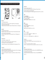
2.8 Fan Speed & Light Control Operation
English /
1. LED Light Control – Press to switch
LEDs color (Blue, Green, Red and
Single LED Flash)
2. Fan Speed Control – Turn clockwise for
higher fan speed
3. Fan Speed Control – Turn
counter-clockwise for lower fan speed
Deutsch /
1. LED Helligkeitssteuerung – Drücken
Sie diesen Schalter, um die
LED-Farben zu wechseln (Blau, Grün,
Rot und einzelnes LED-Blinken)
2. Gebläsegeschwindigkeitssteuerung –
Drehen Sie im Uhrzeigersinn für höhere
Gebläsegeschwindigkeit
3. Gebläsegeschwindigkeitssteuerung –
Drehen Sie gegen den Uhrzeigersinn für
geringere Gebläsegeschwindigkeit
Français /
1. Commande de voyant : appuyez pour
changer la couleur des voyants (bleu, vert,
rouge et voyant clignotant)
2. Commande de vitesse de ventilateur :
tournez dans le sens des aiguilles d’une
montre pour augmenter la vitesse du
ventilateur.
3. Commande de vitesse de ventilateur :
tournez dans le sens inverse des aiguilles
d’une montre pour diminuer la vitesse du
ventilateur.
Español /
1. Control de indicadores LED: pulse para
cambiar el color de los LED (azul, verde,
rojo y parpadeo de un único LED).
2. Control de velocidad del ventilador: gírelo
en el sentido de las agujas del reloj para
aumentar la velocidad del ventilador.
3. Control de velocidad del ventilador: gírelo
en el sentido contrario a las agujas del reloj
para reducir la velocidad del ventilador.
1
2
3
Seite laden ...

22
21
Dotted line A
Dotted line B
(Figure 1)
(For 10.6”) (For 9.6”)
Dotted line B Dotted line ABack of Fan Duct 2
Before sticking
the Mylar on
Fan Duct 2,
bend the Mylar
as Figure 1.
5
6
4
3
2
Fan Duct 1
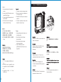
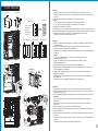
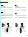
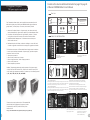
3.0 For 3-Way SLI
English /
1.Squeeze and pull outward the tool-free clip and then move the iCage upward for 4 bays.
2.Put the Fan Duct 1 into the empty 5.25” drive bay cage and secure it to the motherboard plate
by screws.
3.Install the graphic cards and place the Mylar over Fan Duct 2 as shown.
Notice:
For 10.6” graphic card: Align the dotted line B of the Mylar with Fan Duct 2.
For 9.6” graphic card: Align the dotted line A of the Mylar with Fan Duct 2.
4.Secure the 120x38mm fan on Fan Duct 2.
5.Put Fan Duct 2 on the 3-Way graphic cards and secure it to the motherboard plate with screws.
6.Place the sponge between the 120x38mm fan and the motherboard plate to avoid the air leaks.
7.Connect the 3-pin wire of the 120x38mm fan to the motherboard’s fan connector.
Connect the unused power cable to the graphic cards.
Deutsch /
1.Drücken und ziehen den werkzeugfreien Clip nach außen und bewegen Sie dann den iCage 4
Schächte nach oben.
2.Legen Sie die Ventilatordurchführung 1 in den leeren 5,25 Zoll Laufwerksschacht und
befestigen Sie sie mit Schrauben an der Hauptplatine.
3.Installieren Sie die Grafikkarten und platzieren Sie das Mylar über der Ventilatordurchführung 2,
wie gezeigt.
Hinweis:
Für 10,6 Zoll Grafikkarte: Richten Sie die gestrichelte Linie B des Mylar mit der
Ventilatordurchführung 2 aus.
Für 9,6 Zoll Grafikkarte: Richten Sie die gestrichelte Linie A des Mylar mit der
Ventilatordurchführung 2 aus.
4.Sichern Sie den 120x38 mm Ventilator auf der Ventilatordurchführung 2.
5.Bringen Sie die Ventilatordurchführung 2 auf den 3-Wege-Grafikkarten an und sicher Sie sie
auf der Hauptplatine mit Schrauben.
6.Setzen Sie den Schwamm zwischen den 120x38 mm Ventilator und die Hauptplatine, um
Leckagen zu vermeiden.
7.Verbinden Sie das 3-polige Kabel für den 120x38 mm Ventilator mit dem Gebläseanschluss
der Hauptplatine.
Schließen Sie die nicht verwendeten Stromkabel an die Grafikkarten an.
Français /
1.Pressez et tirez vers l’extérieur le clip sans outil, puis déplacez l'iCage 4 baies vers le haut.
2.Placez le Conduit de Ventilation 1 dans la cage vide de la baie de 5,25” et fixez-le à la plaque
de la carte mère avec les vis.
3.Installez les cartes graphiques et placez le Mylar sur le Conduit de Ventilation 2 comme illustré.
Remarque :
Pour la carte graphique de 10,6” : Alignez la ligne pointillée B du Mylar avec le Conduit de
Ventilation 2.
Pour la carte graphique de 9,6” : Alignez la ligne pointillée A du Mylar avec le Conduit de
Ventilation 2.
4.Fixez le ventilateur de 120 x 38mm sur le Conduit de Ventilation 2.
5.Placez le Conduit de Ventilation 2 sur les cartes graphiques 3-Way et fixez-le à la plaque de la
carte mère avec les vis.
6.Placez l'éponge entre le ventilateur de 120 x 38 mm et la plaque de la carte mère pour éviter les
fuites d'air.
7.Connectez le câble à 3 broches du ventilateur de 120 x 38 mm au connecteur de ventilateur de la
carte mère.
Connectez le câble d'alimentation inutilisé aux cartes graphiques.
1
Fan Duct 2Fan Duct 1
Sponge
Fan Duct 2
Seite laden ...

26
25
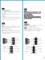
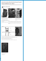
3.1 For Quad SLI
Español /
1.Coloque el ventilador de 120x38 mm en el Conducto del ventilador 3.
2.Extraiga el ventilador de 230 mm de la puerta lateral.
3.Coloque el ventilador de 120x38 mm en la puerta lateral del bastidor perforado (el aire
de entrada se centra en la sección central del SLI cuádruple).
4.Conecte el cable de 3 pines del ventilador de 120x38 mm al conector del ventilador de
la placa base.
Conecte el cable de alimentación sin usar a las tarjetas gráficas.
2
Fan Duct 3
4
3
2
1
English /
1.Place the 120x38mm fan on the Fan Duct 3.
2.Remove the 230mm fan from the side door.
3.Place shrouded 120x38mm fan on perforated chassis side door (inlet air is focused on
Quad SLI middle section).
4.Connect the 3-pin wire of the 120x38mm fan to the motherboard's fan connector.
Connect the unused power cable to the graphic cards.
Deutsch /
1.Sichern Sie den 120x38 mm Ventilator auf der Ventilatordurchführung 3.
2.Entfernen Sie den 230 mm Ventilator aus der Seitentür.
3.Platzieren Sie den ummantelten 120x38 mm Ventilator auf der perforierten seitlichen
Gehäuseabdeckung (die Zuluft wird auf den Quad-SLI mittleren Bereich konzentriert).
4.Verbinden Sie das 3-polige Kabel für den 120x38 mm Ventilator mit dem
Gebläseanschluss der Hauptplatine.
Schließen Sie die nicht verwendeten Stromkabel an die Grafikkarten an.
Italiano /
1.Fissare la ventola da 120x38 mm sul Fan Duct 3.
2.Rimuovere la ventola da 230 mm dal portello laterale.
3.Posizionare la ventola da 120x38 mm rivestita sul portello laterale dello chassis
perforato (l’aria in entrata si concentra sulla sezione centrale dello SLI Quad).
4.Collegare il cavo a 3 pin della ventola da 120x38 mm al connettore della ventola della
scheda madre.
Collegare il cavo di alimentazione inutilizzato alle schede grafiche.
Français /
1.Placez le ventilateur de 120 x 38 mm sur le Conduit de Ventilation 3.
2.Enlevez le ventilateur de 230 mm de la porte latérale.
3.Placez le ventilateur de 120 x 38 mm recouvert d’une grille sur la porte latérale du
châssis perforé (l'air d'arrivée est dirigé vers la partie centrale du Quad SLI).
4.Connectez le câble à 3 broches du ventilateur de 120 x 38 mm au connecteur de
ventilateur de la carte mère.
Connectez le câble d'alimentation inutilisé aux cartes graphiques.
繁體中文 /
1.將 120x38mm 風扇置於風扇導風罩3 上。
2.從機箱側門卸下 230mm 風扇。
3.將導風罩3 與 120x38mm 風扇在機箱側門尋找適當的孔位,加上墊片用螺絲固定(注意: 導
風罩3 內送氣流要對準 Quad SLI 顯示卡中間部分,以便集中冷卻 Quad SLI 顯示卡)。
4.將 120x38mm 風扇的 3-PIN接頭插入主機板的風扇插口。
將未使用的電源線連接至顯示卡。
简体中文 /简体中文 /
1.将 120x38mm 风扇置于风扇导风罩3 上。
2.卸下机箱侧门的 230mm 风扇。
3.将导风罩3 与 120x38mm 风扇在机箱侧门寻找适当的孔位,加上垫片用螺丝固定(注意: 导
风罩3 内送气流要对准 Quad SLI 显示卡中间部分,以便集中冷却 Quad SLI 显示卡)。
4.将 120x38mm 风扇的 3-PIN 接头插入主板的风扇接口。
将未使用的电源线接入显卡。
日本語 /日本語 /
1.ファンダクト3に120x38mmファンを取り付けます。
2.サイドドアから230mmを取り外します。
3.120x38mmファンを穴の開いたシャーシのサイドドアに取り付けます(流入空気はQuad
SLIの中間部分に集中します)。
4.120x38mmファンの3ピンワイヤをマザーボードのファンコネクタに接続します。
未使用の電源ケーブルをグラフィックカードに接続します。
Русский /Русский /
1.Установите вентилятор 120 x 38 мм на воздуховод вентилятора 3.
2.Снимите вентилятор 230 мм с боковой дверцы.
3.Установите вентилятор 120 x 38 мм с кожухом на перфорированную боковую
дверцу корпуса (поступающий воздух направлен на среднюю секцию Quad SLI).
4.Подсоедините 3-контактный провод вентилятора 120 x 38 мм к разъему
вентилятора на материнской плате.
Подсоедините неиспользуемый кабель питания к графическим платам.
Türkçe /
1.120x38mm’lik fanı Fan Kanalı 3 üzerine yerleştirin.
2.230mm’lik fanı yan kapıdan çıkarın.
3.Gizli 120x38mm’lik delikli kasa yan kapısına yerleştirin (giriş havsı Dörtlü SLI’nın orta
bölümüne odaklanır).
4.120x38mm’lik fanın 3 pimli kablosunu ana kartın fan konektörüne bağlayın.
Kullanılmayan güç kablosunu grafik kartına bağlayın.
Washer
Fan Duct 3

28
27
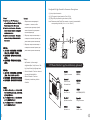
Leads Installation Guide
Case LED connection / On the front of the case, you can find some LEDs and switch leads. Please consult your
user manual of your motherboard manufacturer, then connect these leads to the panel header on the motherboard.
USB 2.0 connection / Please consult your motherboard manual to find out the section of “USB connection”
Audio Connection / Please refer to the following illustration of Audio connector and your motherboard user manual.
Please select the motherboard which used AC’97 or HD Audio(Azalia),(be aware of that your audio supports AC’97
or HD Audio (Azalia)) or it will damage your device(s)
English
Deutsch
Anschlüsse herstellen
Gehäuse-LED-Verbindungen / Auf der Gehäusevorderseite finden Sie einige LEDs und Verbindungen. Bitte nehmen
Sie die Gebrauchsanweisung Ihres Motherboard Herstellers zur Hilfe und schließen Sie diese Verbindungen an die Panel
Header Belegung des Motherboards an.
USB 2.0 Anschluss / Bitte nehmen Sie die Gebrauchsanweisung Ihres Motherboards zur Hilfe und lesen Sie unter
dem Kapitel „USB Anschlüsse“ nach.
Audio Anschlüsse / Bitte beachten Sie die folgende Abbildung der Audio Anschlüsse und die Anweisung in der
Gebrauchsanweisung Ihres Motherboards. Bitte wählen Sie das Motherboard, das AC’97 oder HD Audio(Azalia)
verwendet, (achten Sie darauf, dass Ihr Audio AC’97 bzw. HD Audio (Azalia unterstützt)). Andernfalls entstehen
schwere Schäden an Ihrem(n) Gerät(en)!!!
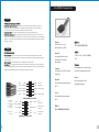
AUDIO AC'97 Function
GROUND
Front
Audio Ground
L-RET
Rear Left Channel
Audio Signal
Rear Right Channel
Audio Signal
R-RET
NC
BROWN
RED
MIC IN
MIC POWER
Front Microphone
Power
Front Microphone
input Signal
KEY
BLUE
NC
BLUE
L-OUT
Front Left Channel
Audio Signal
Front Right Channel
Audio Signal
YELLOW
R-OUT
BLACK
YELLOW
PRESENCE#
BLACK
SENSE1_RETURN
AUD GND
SENSE2_RETURN
YELLOW
BROWN
RED
PORT1 R
PORT2 R
PORT1 L
BLUE
PORT2 L
SENSE_SEND
KEY
PURPLE
GREEN
ORANGE
BLACK
AUDIO AZALIA Function
4.0 Leads Installation Guide
Guide d'installation des fils
Connexion des voyants du boîtier / Sur la face avant du boîtier, vous trouverez plusieurs voyants et les fils des
boutons. S'il vous plaît consultez le guide d'utilisateur du fabricant de votre carte mère, puis connectez ces fils aux
connecteurs sur la carte mère.
Connexion USB 2.0 / S'il vous plaît consultez le manuel de votre carte mère à la section "Connexion USB"
Connexion audio / S'il vous plaît référez vous à l'illustration suivante du connecteur audio et au guide de l'utilisateur
de votre carte mère. S'il vous plaît sélectionnez une carte mère supportant AC'97 ou HD Audi (Azalia), (faites attention
que votre audio supporte l'AC'97 ou HD Audio (Azalia)) sinon cela pourrait endommager votre matériel.
AUDIO AC'97 Function
GROUND
Front
Audio Ground
L-RET
Rear Left Channel
Audio Signal
Rear Right Channel
Audio Signal
R-RET
NC
BROWN
RED
MIC IN
MIC POWER
Front Microphone
Power
Front Microphone
input Signal
KEY
BLUE
NC
BLUE
L-OUT
Front Left Channel
Audio Signal
Front Right Channel
Audio Signal
YELLOW
R-OUT
BLACK
YELLOW
Français
Español
Guía de Instalación de Cables
Conexión del LED de la caja / En la parte frontal de la caja, encontrará algunos LED y cables de interruptores. Consulte
el manual del usuario del fabricante de la placa madre, a continuación conecte estos cables al conector de la placa madre.
Conexión USB 2.0 / Consulte el manual de la placa madre para obtener más información sobre el apartado “Conexión USB"
Conexión de Audio / Consulte la siguiente ilustración del conector de Audio y el manual del usuario de la placa madre.
Seleccione la placa madre que utiliza AC’97 o HD Audio (Azalia), (asegúrese de que su audio admite AC’97 o HD Audio
(Azalia)) si no, sus dispositivos resultarán dañados
PRESENCE#
BLACK
SENSE1_RETURN
AUD GND
SENSE2_RETURN
YELLOW
BROWN
RED
PORT1 R
PORT2 R
PORT1 L
BLUE
PORT2 L
SENSE_SEND
KEY
PURPLE
GREEN
ORANGE
BLACK
AUDIO AZALIA Function
Seite laden ...
Seite laden ...
Seite laden ...
Seite laden ...
-
 1
1
-
 2
2
-
 3
3
-
 4
4
-
 5
5
-
 6
6
-
 7
7
-
 8
8
-
 9
9
-
 10
10
-
 11
11
-
 12
12
-
 13
13
-
 14
14
-
 15
15
-
 16
16
-
 17
17
-
 18
18
-
 19
19


Thermaltake Element V NVIDIA Edition Basic Benutzerhandbuch
- Kategorie
- Computergehäuse
- Typ
- Benutzerhandbuch
in anderen Sprachen
- English: Thermaltake Element V NVIDIA Edition Basic User manual
- français: Thermaltake Element V NVIDIA Edition Basic Manuel utilisateur
- español: Thermaltake Element V NVIDIA Edition Basic Manual de usuario
- italiano: Thermaltake Element V NVIDIA Edition Basic Manuale utente
- русский: Thermaltake Element V NVIDIA Edition Basic Руководство пользователя
- 日本語: Thermaltake Element V NVIDIA Edition Basic ユーザーマニュアル
- Türkçe: Thermaltake Element V NVIDIA Edition Basic Kullanım kılavuzu
Verwandte Papiere
-
Thermaltake AF0023 Benutzerhandbuch
-
-
-
-
Thermaltake Silver River II 3.5" Benutzerhandbuch
-
-
-
-
-