Pepperl+Fuchs ACX04-F99-I-V15 Bedienungsanleitung
- Typ
- Bedienungsanleitung

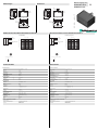
Abmessungen
Elektrischer Anschluss/Kurven/
Zusätzliche Informationen
Electrical Connection / Curves / Additional Information
Dimensions
Technische Daten
Technical data
ACX04-F99-I-V15
104510
64
65
4 x ø 5.5
M12
730 718.5
37
LEDs
104510
64
65
4 x ø 5.5
M12
730 718.5
37
LEDs
Analogausgang X
1+UB
-UB
5
2
4
3
Teach-In
n.c.
1
3
4
5
2
01 10 100 1000
-2
-4
-6
-8
-10
-12
-14
Frequenzgang
20 x log (Ausgangssignal / Stimulus) [dB]
Frequenz [Hz]
01 10 100 1000
-2
-4
-6
-8
-10
-12
-14
Frequency response
20 x log (output signal / stimulus) [dB]
frequency [Hz]
Analog output X
1+UB
-UB
5
2
4
3
Teach-In
n.c.
1
3
4
5
2
Part. No.:
Date:
227701
11/03/2010 DIN A3 -> DIN
45-3367
Doc. No.:
1 BN
2 WH
3 BU
4 BK
5 GY
Wire colors in accordance with EN 60947-5-2
1 BN
2 WH
3 BU
4 BK
5 GY
Adernfarben gemäß EN 60947-5-2
Allgemeine Daten
Typ Beschleunigungssensor, 1-achsig
Messbereich -2 ... 2 g
Auflösung 5 mg
Reproduzierbarkeit ± 5 mg
Frequenzbereich 0 ... 100 Hz
Anzeigen/Bedienelemente
Betriebsanzeige LED, grün
Teach-In-Anzeige LED, gelb
Elektrische Daten
Betriebsspannung UB10 ... 30 V DC
Leerlaufstrom I0 25 mA
Bereitschaftsverzug tv 100 ms
Analogausgang
Ausgangstyp 1 Stromausgang 4 ... 20 mA
Nullpunkt 12 mA
Steilheit der Ausgangskennlinie 4 mA / g
Linearitätsfehler ± 1,2 %
Lastwiderstand 0 ... 200 bei UB = 10 ... 18 V
0 ... 500 bei UB = 18 ... 30 V
Temperatureinfluss
Offset ± 4 A /K
Steilheit ± 20 A / g
Umgebungsbedingungen
Umgebungstemperatur -40 ... 85 °C (-40 ... 185 °F)
Lagertemperatur -40 ... 85 °C (-40 ... 185 °F)
Mechanische Daten
Anschlussart Gerätestecker M12 x 1, 5-polig
Gehäusematerial PA
Schutzart IP68 / IP69K
Masse 240 g
Normen- und Richtlinienkonformität
Normenkonformität
Schock- und Stoßfestigkeit 100 g gemäß DIN EN 60068-2-27
Normen EN 60947-5-2:2007
IEC 60947-5-2:2007
General specifications
Type 1 axis acceleration sensor
Measurement range -2 ... 2 g
Resolution 5 mg
Repeat accuracy ± 5 mg
Frequency range 0 ... 100 Hz
Indicators/operating means
Operating display LED, green
TEACH-IN indication LED, yellow
Electrical specifications
Operating voltage UB10 ... 30 V DC
No-load supply current I0 25 mA
Time delay before availability tv 100 ms
Analog output
Output type 1 current output 4 ... 20 mA
Zero signal 12 mA
Slope of output characteristic 4 mA / g
Linearity error ± 1.2 %
Load resistor 0 ... 200 at UB = 10 ... 18 V
0 ... 500 at UB = 18 ... 30 V
Temperature influence
Offset ± 4 A / K
Slope ± 20 A / g
Ambient conditions
Ambient temperature -40 ... 85 °C (-40 ... 185 °F)
Storage temperature -40 ... 85 °C (-40 ... 185 °F)
Mechanical specifications
Connection type M12 x 1 connector, 5-pin
Housing material PA
Protection degree IP68 / IP69K
Mass 240 g
Compliance with standards and directives
Standard conformity
Shock and impact resistance 100 g according to DIN EN 60068-2-27
Standards EN 60947-5-2:2007
IEC 60947-5-2:2007
Beschleunigungssens
Acceleration sensor

Adressen / Addresses / Adresses / Direcciónes / Indirizzi
Contact Pepperl+Fuchs GmbH · 68301 Mannheim · Germany · Tel. +49 621 776-4411 · Fax +49 621 776-27-4411 · E-mail: fa-i[email protected]uchs.com
Worldwide Headquarters: Pepperl+Fuchs GmbH · Mannheim · Germany · E-mail: [email protected]fuchs.com
USA Headquarters: Pepperl+Fuchs Inc. · Twinsburg · USA · E-mail: fa-info@us.pepperl-fuchs.com
Asia Pacific Headquarters: Pepperl+Fuchs Pte Ltd · Singapore · E-mail: fa-info@sg.pepperl-fuchs.com · Company Registration No. 199003130E
For more contact-adresses refer to the catalogue or internet: http://www.pepperl-fuchs.com
Einbaulage
Im Auslieferungszustand ist die Null-Lage der Sensorachsen erreicht, wenn der Sensor auf einer horizontalen Ebene flach aufgebaut ist und der elek-
trische Anschluss des Sensors waagerecht zur Seite weist.
LED-Anzeige
Werkseinstellungen
siehe Technische Daten
Einlernen des Nullpunktes
1. Bringen Sie den Sensor in die Nullpunkt-Position
2. Legen Sie die Spannung +UB für 1 s ... 10 s an den Teach In Eingang (Pin 5)
3. Zur Bestätigung leuchtet die Teach In LED
4. Trennen Sie den Teach In Eingang vor Ablauf von 10 s von +UB
5. Zur Bestätigung blinkt die Teach In LED 3 mal
6. Der Nullpunkt ist nun eingelernt und der Sensor kehrt in den Normalbetrieb zurück (siehe LED-Anzeige).
Rücksetzen des Sensors auf Werkseinstellungen
1. Legen Sie die Spannung +UB für 20 s ... 25 s an den Teach In Eingang (Pin 5)
2. Zur Bestätigung leuchtet die Teach In LED
3. Trennen Sie den Teach In Eingang vor Ablauf von 25 s von +UB
4. Zur Bestätigung blinken die Teach In LED und die Out LED 3 mal
5. Der Sensor ist nun auf Werkseinstellungen zurückgesetzt und kehrt in den Normalbetrieb zurück (siehe LED-Anzeige).
Unterspannungs-Erkennung
Unterschreitet die Versorgungsspannung einen Wert von ca. 7 V, so werden alle Ausgänge und gelben LEDs abgeschaltet. Die grüne LED „power“
blinkt schnell. Überschreitet die Versorgungsspannung einen Wert von ca. 8 V, so setzt der Sensor seinen Normalbetrieb fort.
Montage des Sensors
Neigungssensoren der Baureihe -F99 bestehen aus dem Sensormodul und dem dazugehörigen Gehäuse aus Aluminium-Druckguss. Wählen Sie zur
Montage des Sensors eine ebene Fläche mit den Mindestabmessungen 70 mm x 50 mm.
Zur Sensormontage gehen Sie wie folgt vor:
1. Lösen Sie die Zentralschraube unterhalb des Sensoranschlusses.
2. Schieben Sie das Klemmelement so weit zurück, bis Sie das Sensormodul aus dem Gehäuse entnehmen können.
3. Nehmen Sie das Sensormodul aus dem Gehäuse.
4. Positionieren Sie das Gehäuse am gewünschten Montageort und befestigen Sie es mit vier Senkkopfschrauben. Achten Sie darauf, dass die
Schraubenköpfe nicht überstehen.
5. Setzen Sie das Sensormodul in das Gehäuse ein.
6. Schieben Sie das Klemmelement bündig in das Gehäuse. Kontrollieren Sie den ordnungsgemäßen Sitz des Sensorelements.
7. Ziehen Sie nun die Zentralschraube fest.
Der Neigungssensor ist nun montiert.
Störaussendung und Störfestigkeit nach KFZ-Richtlinie 2006/28/EG (e1 Typgenehmigung)
Störfestigkeit nach DIN ISO 11452-2: 100 V/m
Frequenzband 20 MHz bis 2 GHz
Leitungsgeführte Störgrößen nach ISO 7637-2:
Anzeigen in Abhängigkeit des Betriebszustandes LED grün
Power
LED gelb 1 LED gelb 2
Normalbetrieb ein aus aus
Einlernen des Nullpunktes
Teach In (Pin 5 an +UB) für 1 s ... 10 s
fallende Flanke an Teach In
danach Wechsel in Normalbetrieb
ein
ein
ein
ein
blinkt 3 x
aus
aus
aus
aus
Rücksetzen auf Werkseinstellungen:
Teach In (Pin 5 an +UB) für 20 s ... 25 s
fallende Flanke an Teach In
Ende des Rücksetzvorgangs danach Normalbetrieb
ein
ein
ein
ein
blinkt 3 x
aus
aus
blinkt 3 x
aus
Unterspannung blinkt aus aus
EMV-Eigenschaften
Impuls 1 2a 2b 3a 3b 4
Schärfegrad III III III III III III
Ausfallkriterium C A C A A C
EN 61000-4-2: CD: 8 kV / AD: 15 kV
Schärfegrad IV IV
EN 61000-4-3: 30 V/m (80...2500 MHz)
Schärfegrad IV
EN 61000-4-4: 2 kV
Schärfegrad III
EN 61000-4-6: 10 V (0,01...80 MHz)
Schärfegrad III
EN 55011: Klasse A
1.
2.
3.
Installation orientation
On delivery, the zero position of the sensor axes is achieved when the sensor is mounted flat on a horizontal plane and the electrical connection of the
sensor points horizontally sidewards.
LED display
Factory settings
see Technical Data
Teach-in of reference point (output S1)
1. Move sensor to reference position
2. Apply supply voltage (+Ub) to Teach In input (Pin 5) for 1 s ... 10 s
3. Teach In LED lights up for confirmation
4. Disconnect Teach In input (Pin 4) before the 10 s time elapses
5. Teach In LED flashes 3 x for confirmation
6. Reference point is now programmed and the sensor returns to normal operation (see LED display)
Resetting the sensor to factory settings
1. Apply supply voltage (+Ub) to Teach In input (Pin 5) for 20 s ... 25 s
2. Teach In LED lights up for confirmation
3. Disconnect Teach In input (Pin 4) before the 25 s time elapses
4. Teach In LED and Out LED flash 3 x for confirmation
5. The sensor is now reseted to factory settings and returns to normal operation (see LED display)
Undervoltage detection
If the supply voltage falls below a value of approx. 7 V, all outputs and yellow LEDs are deactivated. The green "power" LED flashes rapidly. If the supply
voltage rises above a value of approx. 8 V, the sensor continues with normal operation.
Mounting of the sensor
Inclination sensors from the -F99 series consist of a sensor module and accompanying cast aluminum housing. Select a flat surface with minimum dimen-
sions of 70 mm x 50 mm to mount the sensor.
Mount the sensor as follows:
1. Loosen the central screw under the sensor connection.
2. Slide back the clamping element until you are able to remove the sensor module from the housing.
3. Remove the sensor module from the housing
4. Position the housing at the required mounting location and secure using four countersunk screws. Make sure that the heads of the screws do not
protrude.
5. Place the sensor module in the housing.
6. Slide the clamping element flush into the housing. Check that the sensor element is seated correctly.
7. Finally tighten the central screw.
The inclination sensor is now mounted correctly.
EMC Properties
Emitted interference and interference immunity in accordance with motor vehicle directive 2006/28/EG (e1 Type approval)
Interference immunity in accordance with
DIN ISO 11452-2: 100 V/m
Frequency band 20 MHz up to 2 GHz
Mains-borne interference in accordance with ISO 7637-2:
Displays dependent on the operating state LED green:
Power
LED yellow 1 LED yellow 2
Normal operation on off off
Teach In of reference point
Teach In (Pin 5 connected to +UB) for 1 s ... 10 s
falling slope at Teach In input
then sensor returns to normal operation.
on
on
on
on
flashes 3 x
off
off
off
off
Reset to factory settings:
Teach In (Pin 5 connected to +UB) for 20 s ... 25 s
falling slope at Teach In input
then sensor returns to normal operation.
on
on
on
on
flashes 3 x
off
off
flashes 3 x
off
Undervoltage flashes off off
Pulse 1 2a 2b 3a 3b 4
Severity level III III III III III III
Failure criterion C A C A A C
EN 61000-4-2: CD: 8 kV / AD: 15 kV
Severity level IV IV
EN 61000-4-3: 30 V/m (80...2500 MHz)
Severity level IV
EN 61000-4-4: 2 kV
Severity level III
EN 61000-4-6: 10 V (0.01...80 MHz)
Severity level III
EN 55011: Klasse A
1.
2.
3.
-
 1
1
-
 2
2


Pepperl+Fuchs ACX04-F99-I-V15 Bedienungsanleitung
- Typ
- Bedienungsanleitung
in anderen Sprachen
Verwandte Artikel
-
Pepperl+Fuchs INX360D-F99-U2E2-V15 Bedienungsanleitung
-
-
-
-
-
-
-
-
-