EverFocus NeVio EZN850 Installationsanleitung
- Typ
- Installationsanleitung


EZN850
2
This installation guide provides instructions for installing the EZN850 IP Camera. For
all other aspects of using this product, please refer to EZN850 User’s Manual, which
is available on the CD included in this package.
Installation steps
1. Confirm that your PC meet minimum computer requirement listed below.
2. In order to configure IP cameras and Encoders, Internet Explorer is required for
login the system. PC network setting must be done prior to camera configuration
setup. Please ensure your PC relative connections are correctly and affirmatively
linked. Please consult your ISP or network administrators for more detail of network
setting reference.
3. Mount the camera and connect Cables. Please see "3. Installation” on page 9.
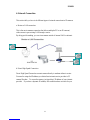
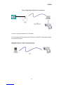
4. Network Connection. 3 typical types of network connection. Please see “6.
Network Connection” on page 21.
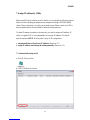
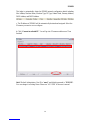
5. Set up IP address and network setting by IP Utility. See “7. Assign IP address by
Utility” on page 23.
Package Contents
Network camera (x1)
Printed Installation Guide (x1)
Software APs including user’s manual CD (x1)
Mounting kit includes:
-Long Screws x 4 (for mounting bracket)
-Short Screws x 4 (for connecting camera body to bracket)
-Expanding Screws x 4
-Hex key x 1 (for adjusting bracket)
-Hexagon wrench x 1 (for adjusting sunshield)
Minimum Computer Requirements
-CPU: PC Pentium IV (2.0 GHz or higher) / AMD Athlon (or higher)
-VGA card: 32 MB min. 16.7 million colours, with DirectX9.0c support
-Memory: 512 MB RAM min., 1 GB HD space or above
Additional HD space depends on required local storage of video files,
100 Mbps network card
-Screen Resolution: 1024 x 768 pixels or higher, 32-bit pixel color resolution
-Operating system: Windows XP, service pack 3 or higher
-Software: DirectX9,0c, Internet Explorer 6.0 or higher
Note!! Please connect to Microsoft’s Web Site for downloading.


EZN850
5
Table Of Contents
1. Camera Component Description..............................................................................6
2. Back Panel Layout....................................................................................................7
2.1 Terminal Connector...........................................................................................8
3. Installation ................................................................................................................9
3.1 Wiring and Mounting......................................................................................10
3.2 Adjusting Camera Position .............................................................................16
3.3 Adjusting Vari-focal Lens................................................................................17
4. Lens Adjustment......................................................................................................18
4.1 Lens Setting ......................................................................................................18
5. OSD Configuration.................................................................................................19
6. Network Connection ...............................................................................................21
7. Assign IP address by Utility ....................................................................................23
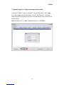
7.1 Automatically assign an IP..............................................................................23
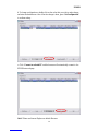
7.2 Manually assign an IP address and change network setting .......................25


EZN850
7
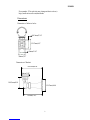
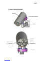
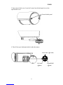
2. Back Panel Layout
1. SD card slot: Slot to insert SD card
2. Reset: Loading factory default configuration by pressing the button, which is
inside this hole. Please insert the keen-edged device to the hole for 10 seconds.
3. Video output: Composite video BNC output socket. Connect Video output only
for installation usage.
4. Terminal Connector: The terminal connector provides the interface to alarm input
& output, RS-485, GND and IR illuminator power source. (please see “2.1
Terminal Connector”)
5. Control key selection switch
Switch to OSD to control OSD menu by using the control key or switch to LENS
to adjust zooming and focus by using the control key (please refer to “4.1 Lens
setting” and “5. OSD Configuration” for details).
6. Ethernet RJ-45 port: Connect to LAN via this standard RJ-45 connector.
Yellow indicator light: On means 100Mbps, Off means 10Mbps
Green indicator light: On means link, flicking means active, Off means link fail
7. Power Input Terminal
Connect the appropriate power to each model. N/L is used to connect to power
in. PE is a ground pin. Two models of 24VAC and 100-240VAC are available as
power source of EZN850 camera. N/L and PE apply to 100-240VAC model
only.
Note!! Please do NOT connect 100-240VAC power to 24VAC model. It will
damage the machine.
1
2
5
3
4
6
7

EZN850
8
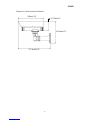
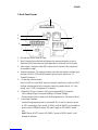
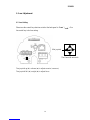
2.1 Terminal Connector
-Alarm: Connect to Alarm In/Out device
-12VDC: Provide power source for IR illuminator (Max. load is = 1A; IR illuminator
is optional)
-GND: Ground pin for illuminator
-RS485 (+-): A half-duplex RS-485 interface for keyboard controlling
Terminal connector schematic diagram
DC OUT

EZN850
9
3. Installation
This section will describe, in general terms, how to install the EZN850 camera. Here are
the following processes:
-Wire and mount the camera. See “3.1 Wire and Mounting”.
-Adjust the camera position. See “3.2 Adjusting camera position”.
-Adjust the lens. See “3.3 Adjusting lens”.
*Warning*
•
To prevent electrical shock, turn off the electrical power before making
electrical connections.
•
Do not expose the appliance to water or moisture, nor try to operate it in wet
areas.

EZN850
10
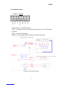
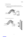
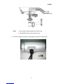
3.1 Wiring and Mounting
1. Wire internet cable, power cable and Alarm/RS485 cable through the bracket.
Note!! Please use Internet cable without RJ45 connector otherwise you cannot
go through cable gland.
2. Fix the bracket to wall by using 4 screws.
LAN cable
Power
cable
LAN cable
Power cable
Alarm/RS485 cable
Alarm/RS485 cable


EZN850
12
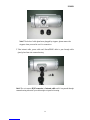
Note!! The holes of cable gland were plugged by stoppers, please remove the
stoppers when you need to use it for connection.
5. Take internet cable, power cable and Alarm/RS485 cable to pass through cable
gland, place them into camera housing.
Note!! Do not connect RJ45 connector to Internet cable until it has passed through
camera housing otherwise your cable might not pass the housing.


EZN850
14
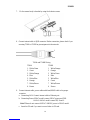
7. Fix the camera body to bracket by using the 4 shorter screws.
8. Connect internet cable to RJ45 connector. Before connection, please check if you
are using T568A or T568B as pin assignment in the network.
T568A and T568B Wiring
9. Connect internet cable, power cable and Alarm/RS485 cable to the proper
connector.
a. Connecting LAN: Connect internet cable to Ethernet port.
b. Connecting Power-24VAC model: connect 24VAC power and GND.
100VAC~240VAC m
odel: connect PE, N and L.
Note!! Please do not connect 100VAC~240VAC power to 24VAC model.
c. Insert the SD card if you want to record video in SD card.
1
8
T568B
1 White/Orange
2 Orange
3 White/Green
4 Blue
5 White/Blue
6 Green
7 White/Brown
8 Brown
T568A
1. White/Green
2. Green
3. White/Orange
4. Blue
5. White/Blue
6. Orange
7. White/Brown
8. Brown

EZN850
15
*Warning*
•
To prevent electrical shock, turn off the electrical power before making
electrical connections.
•
Do not connect high voltage power to the camera. It may damage the camera.
•
Do not short circuit the power leads and expose the wire when connecting the
power supply to the camera.
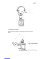
d. Connecting Alarm/RS485 (optional): Connect Alarm cable to Alarm connector
and RS485 cable to 485+ and 485-. Please use screw driver to lose and tight the
screw under the connector when you do connection. The terminal connector is
removable for easier connection.
10. Close the back cover and screw the 2 screws firmly. Now, you are done with the
installation.
Note!! Before you close the cover, please make sure control key is attached firmly
and wire doesn’t stuck.
Alarm/RS485 cable LAN cable
Power cable


EZN850
18
4. Lens Adjustment
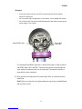
4.1 Lens Setting
Please turn the control key selection switch at the back panel to “Lens” ( ). Use
the control key to do lens setting.
Turn joystick up () or down () to adjust zoom in / zoom out,
Turn joystick left () or right () to adjust focus.
The Cursors & mini stick
Mini joystick
UP

EZN850
19
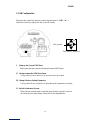
5. OSD Configuration
Please turn the control key selection switch at the back panel to “OSD” ( ).
Detach the control key and use this key to do OSD setting.
I. Bring up the General OSD Menu
Simply press the mini-joystick to bring up the general OSD menu.
II. Navigate among the OSD Menu Items
Turn joystick up () or down () to move the cursor up or down.
III. Change Modes or Setting Parameters
Turn joystick left () or right () to adjust the mode or parameter of settings.
IV. Switch to Sub-menu Screens
When the item with sub-menu is selected, press the mini-joystick to switch to
the sub-menu for further settings. Please refer to the diagram below.
The Cursors & mini stick
Mini joystick
UP

EZN850
20
Note!!
For those selected items with “ ” sign in the end, they have the sub-menu for
further settings.
V. Return to Previous Page
Press the mini-joystick to return to previous page.
VI. Close the Host Menu Screen
To close the menu screen, navigate to the “EXIT” item and press the
mini-joystick.
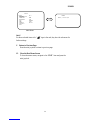
Sub-Menu
Main Menu
LENS
LEVEL |+++++++++| 25
SETUP
> LENS DC
<┘
SHUTTER ___
WHITE BAL. ATW
BACKLIGHT OFF
AGC MIDDLE
DNR LOW
SENS-UP AUTO <┘
SPECIAL <┘
EXIT
Seite wird geladen ...
Seite wird geladen ...
Seite wird geladen ...
Seite wird geladen ...
Seite wird geladen ...
Seite wird geladen ...
Seite wird geladen ...
Seite wird geladen ...
-
 1
1
-
 2
2
-
 3
3
-
 4
4
-
 5
5
-
 6
6
-
 7
7
-
 8
8
-
 9
9
-
 10
10
-
 11
11
-
 12
12
-
 13
13
-
 14
14
-
 15
15
-
 16
16
-
 17
17
-
 18
18
-
 19
19
-
 20
20
-
 21
21
-
 22
22
-
 23
23
-
 24
24
-
 25
25
-
 26
26
-
 27
27
-
 28
28


