
1
FRANÇAIS
ENGLISH
DEUTSCH
ITALIANO
ESPANOL
Mode d’emploi
User’s manual
Bedienungsanleitung
Libretto d’istruzioni
Manual de instrucciones
■■
■■
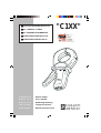
■PINCES AMPEREMETRIQUES AC
■■
■■
■AC CURRENT CLAMPS
■■
■■
■AC ZANGENSTROMWANDLER
■■
■■
■PINZE AMPEROMETRICHE CA
■■
■■
■PINZA AMPERIMETRICAS AC
"C1XX"

2
Signification du symbole
Attention ! Consulter le mode d’emploi avant d’utiliser l’appareil.
Dans le présent mode d’emploi, les instructions précédées de ce symbole, si elles ne sont pas bien
respectées ou réalisées, peuvent occasionner un accident corporel ou endommager l’appareil et les
installations.
Signification du symbole
Cet appareil est protégé par une isolation double ou une isolation renforcée. Il ne nécessite pas de
raccordement à la borne de terre de protection pour assurer la sécurité électrique.
Signification du symbole
Pince équipée en sortie d’un limiteur électronique assurant une protection contre les surtensions
provoquées à l’ouverture accidentelle du circuit secondaire de la pince : 30 V crête maxi.
Signification du symbole CAT III
Cette pince, de catégorie de surtension III et de degré de pollution 2, répond aux exigences de
fiabilité et de disponibilité sévères correspondant aux installations fixes industrielles et domestiques
(cf. IEC 664-1).
Vous venez d’acquérir une pince ampèremétrique de la série "C1XX" et nous vous remercions de
votre confiance.
Pour obtenir le meilleur service de votre appareil :
nlisez attentivement ce mode d’emploi,
nrespectez les précautions d’emploi.
PRECAUTIONS D’EMPLOI
nNe pas mesurer des courants supérieurs à 1200 A et limiter le temps d’utilisation au delà de 1000 A
(voir 4.4.1 Surcharges et 4.4.2 Fréquences).
nNe pas utiliser sur des conducteurs non isolés dont le potentiel est supérieur à 600 V par rapport à la
terre et de catégorie de surtension supérieure à III.
nRespecter les conditions d'environnement (voir 4.4.3)
nMaintenir l’entrefer en parfait état de propreté (voir 5.1 Entretien).
GARANTIE
Notre garantie s’exerce, sauf stipulation expresse, pendant douze mois après la date de mise à disposition
du matériel (extrait de nos Conditions Générales de Vente, communiquées sur demande).
English .............................................................................................................................................. 9
Deutsch........................................................................................................................................... 16
Italiano............................................................................................................................................. 23
Español ........................................................................................................................................... 30

3
SOMMAIRE
1. Présentation.................................................................................................................................. 3
2. Description................................................................................................................................... 3
3. Utilisation ..................................................................................................................................... 4
4. Caractéristiques .......................................................................................................................... 4
4.1 Conditions de référence ....................................................................................................... 4
4.2 Spécifications et références pour commander ................................................................... 4
4.3 Précision et déphasage........................................................................................................ 5
4.4 Conditions d’utilisation........................................................................................................... 6
4.5 Dimensions et masse ........................................................................................................... 7
4.6 Conformité aux normes internationales ............................................................................... 7
5. Maintenance................................................................................................................................. 8
5.1 Entretien ................................................................................................................................ 8
5.2 Vérification métrologique....................................................................................................... 8
5.3 Réparations........................................................................................................................... 8
6. Annexe .......................................................................................................................................... 28
1. PRESENTATION
Les pinces de la série "C100" sont destinées à la mesure de courants alternatifs, sur les installations de
petites et moyennes puissances, de 0,1 A à 1200 A~ (ou à partir de 1 mA ~ pour certains modèles. Voir
4. Caractéristiques).
Elles sont utilisables sur tout multimètre, wattmètre, enregistreur ou oscilloscope pour la C160. Suivant
le modèle (Voir 4.2) : sortie mono ou multicalibre en courant alternatif, ou tension alternative.
Elles bénéficient d’une isolation double ou isolation renforcée et de la conformité aux normes
internationales, notamment l’EN 61010-2-032 : 2003 "pinces ampèremétriques". (Voir 4.6).
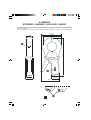
2. DESCRIPTION
(Voir dessin en 6. Annexe)
➊Sortie douilles Ø 4 mm ou cordon (suivant modèle) : longueur du cordon 1,50 m et 2 m pour le modèle
C160.
➋Commutateur de rapport pour modèles multicalibre.
➌La flèche en relief sur le dessus de la mâchoire indique le sens du courant. On considère que le
courant circule dans le sens positif lorsqu’il circule du producteur de courant vers le consommateur
de courant. Cette orientation de la pince est nécessaire lors d’une mesure de puissance (mesure du
courant parallèlement à la tension).

4
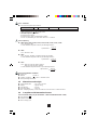
3. UTILISATION
De 1000 à 1200 A, limiter le temps d’utilisation : 15 minutes de marche et 30 minutes d’arrêt.
Pour le modèle C100, non protégé en sortie par limiteur, ne pas enserrer un conducteur avant de
connecter la pince à l’appareil de mesure associé. De la même manière ne pas déconnecter la pince de
l’appareil de mesure quand la pince enserre le câble.
nAvant de raccorder la pince au multimètre vérifier que ce dernier dispose d’un calibre approprié.
nOuvrir les mâchoires et enserrer le câble parcouru par le courant à mesurer. Centrer au mieux le
câble dans les mâchoires. Respecter le sens de la flèche si l’application le nécessite.
nPour lire la mesure, appliquer le cœfficient de lecture adéquat (Voir 4.2 "Rapport entrée / sortie").
NB : pour les modèles multicalibre, sélectionner le rapport donnant les meilleures résolution et précision.
4. CARACTERISTIQUES
4.1 Conditions de référence
nTempérature : +20... +26°C
nTaux d’humidité : 20... 75% HR
nConducteur centré dans les mâchoires
nCourant sinusoïdal : 48... 65 Hz.
nFacteur de distortion : < 1%
nCourant continu: absence
nChamp magnétique continu: champ terrestre (< 40 A/m).
nChamp magnétique alternatif : absence
nProximité de conducteurs extérieurs : absence de courant.
nImpédance de l’appareil de mesure
- C100 / C102 / C103 : ≤ 5 Ω
- C112 / 113 : ≤ 1 Ω
- C122 / C148 : ≤ 0,2 Ω
- C106 / C107 / C116 / C117 : ≥ 1 MΩ et ≤ 100 pF
- C160 : ≥ 1 MΩ et ≤ 47 pF
- C173 : ≥ 10 MΩ et ≤ 100 pF
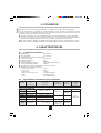
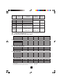
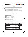
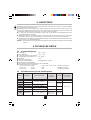
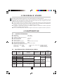
4.2 Spécifications et références pour commander
Référence Etendue Sortie
Modèle pour de mesure Rapport Raccor- protégée
commander nominale Sortie/Entrée dement contre
surtensions
Sortie courant alternatif
C100 P01.1203.01 100 mA...1000 A Douilles Non
C102 P01.1203.02 1 mA~ / 1 A~ Douilles
C112 P01.1203.14 10 mA...1000 A
C103 P01.1203.03 100 mA...1000 A 1 mA~ / 1 A~ Cordons 30 V
C113 P01.1203.15 10 mA...1000 A crête maxi
C122 P01.1203.06 1 A...1000 A 5 mA~ / 1 A~ Douilles
5 mA~ / 1 A~
C148 P01.1203.07 1 A...1000 A 10 mA~ / 1 A~ Douilles
20 mA~ / 1 A~

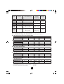
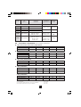
5
Référence Etendue
Modèle pour de mesure Rapport Raccor-
commander nominale Sortie/Entrée dement
Sortie tension alternative
C106 P01.1203.04 100 mA...1000 A 1 mV~ / 1 A~ Douilles
C116 P01.1203.16 10 mA...1000 A
C107 P01.1203.05 100 mA...1000 A 1 mV~ / 1 A~ Cordon
C117 P01.1203.17 10 mA...1000 A
1 A...1000 A 1 mV~ / 1 A~ Cordon
C160 P01.1203.08 100 mA... 100 A 10 mV~ / 1 A~ BNC
100 mA... 10 A 100 mV~ / 1 A~
1 A... 1000 A 1 mV~ / 1 A~
C173 P01.1203.09 100 mA... 100 A 10 mV~ / 1 A~ Cordon
10 mA...10 A 100 mV~ / 1 A~
1 mA... 1 A 1000 mV~ / 1 A~
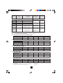
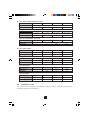
4.3 Précision et déphasage (dans les conditions de référence)
nC100 / C102 / C103 / C106 / C107 : calibre 1000 A
Intensité en A~0,1...10 A 10 A 50 A 200 A 1000...1200 A
Erreur intrinsèque (1) ≤ 3% (3) ≤ 3% ≤ 1,5% ≤ 0,75% ≤ 0,5%
Déphasage (2) ≤ 3° ≤ 1,5° ≤ 0,75° ≤ 0,5°
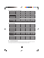
nC112 / C113 / C116 / C117 : calibre 1000 A
Intensité en A~10...100 mA 0,1...1 A 1...10 A 10...100 A 100...1200 A
Erreur intrinsèque (1) ≤ 3% (4) ≤ 2% (5) ≤ 1% ≤ 0,5% ≤ 0,3%
Déphasage (2) (2) ≤ 2° ≤ 1° ≤ 0,7°
nC122 / C148 : calibre 1000 A
Intensité en A~1...20 A 20 A 50 A 200 A 1000...1200 A
Erreur intrinsèque (1) 6% (6) ≤ 5% ≤ 3% ≤ 1,5% ≤ 1%
Déphasage (2) ≤ 5° ≤ 3° ≤ 1,5° ≤ 1°
nC148 : calibre 500 A
Intensité en A~1...10 A 10 A 25 A 100 A 500...600 A
Erreur intrinsèque (1) 6% (7) ≤ 6% ≤ 3% ≤ 2% ≤ 1%
Déphasage (2) ≤ 6° ≤ 4° ≤ 3° ≤ 2,5°
C148 : calibre 250 A
Intensité en A~1...5 A 5 A 12,5 A 50 A 250...300 A
Erreur intrinsèque (1) 10% (8) ≤ 10% ≤ 5% ≤ 2% ≤ 2%
Déphasage (2) (2) ≤ 10° ≤ 10° ≤ 10°
(1) En % du signal de sortie (5) + 3 µA pour C112 / C113 ou + 3 µV pour C116 / C117
(2) Non spécifié (6) + 0,5 mA
(3) + 0,1 mA pour C100 / C102 / C103 ou + 0,1 mV pour C106 / C107 (7) + 1 mA
(4) + 5 µA pour C112 / C113 ou + 5 µV pour C116 / C117 (8) + 2 mA

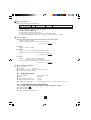
6
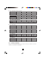
nC160 : calibre 1000 A (2000 A crête maxi)
Intensité en A~1...50 A 50...200 A 200...1000 A 1000...1200 A
Erreur intrinsèque (1) ≤ 1% + 1 mV
Déphasage (2) ≤ 3° ≤ 2° ≤ 1°
C160 : calibre 100 A (300 A crête maxi)
Intensité en A~0,1...5 A 5...20 A 20...100 A 100...120 A
Erreur intrinsèque (1) ≤ 2% + 5 mV
Déphasage (2) ≤ 15° ≤ 10° ≤ 5°
C160 : calibre 10 A (30 A crête maxi)
Intensité en A~0,1...0,5 A 0,5...2 A 2...10 A 10...12 A
Erreur intrinsèque (1) ≤ 3% + 10 mV
Déphasage (2) (2) ≤ 15° ≤ 15°
(1) En % du signal de sortie (2) Non spécifié
nC173 : calibre 1000 A
Intensité en A~1...10 A 10...100 A 100...1000 A 1000...1200 A
Erreur intrinsèque (1) ≤ 1% + 0,2 mV ≤ 0,5% + 0,2 mV ≤ 0,2% ≤ 0,2%
Déphasage (2) ≤ 2° ≤ 1° ≤ 1°
C173 : calibre 100 A
Intensité en A~0,1...1 A 1...10 A 10...100 A 100...120 A
Erreur intrinsèque (1) ≤ 1% + 0,2 mV ≤ 0,5% + 0,2 mV ≤ 0,3% ≤ 0,2%
Déphasage (2) ≤ 2° ≤ 1° ≤ 1°
C173 : calibre 10 A
Intensité en A~0,01...0,1 A 0,1...1 A 1...10 A 10...12 A
Erreur intrinsèque (1) ≤ 1% + 0,2 mV ≤ 0,5% + 0,2 mV ≤ 0,5% ≤ 0,5%
Déphasage (2) ≤ 5° ≤ 2° ≤ 2°
C173 : calibre 1 A
Intensité en A~0,001...0,01 A 0,01...0,1 A 0,1...1 A 1...1,2 A
Erreur intrinsèque (1) ≤ 3% + 1 mV ≤ 3% + 1 mV ≤ 0,7% + 1 mV ≤ 0,7% + 1 mV
Déphasage (2) (2) ≤ 10° ≤ 10°
(1) En % du signal de sortie (2) Non spécifié
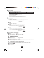
4.4 Conditions d’utilisation
Les pinces "C100" doivent être utilisées dans les conditions suivantes pour satisfaire à la sécurité de
l’utilisateur et aux performances métrologiques.

7
4.4.1 Surcharges
nLimiter le temps d’utilisation au-delà de 1000 A.
Intensité I < 1000 A~ 1000 A~ < I < 1200 A~
Fonctionnement Permanent (1) 15 min. de marche et 30 min. d’arrêt
(1) Avec une fréquence F < 1 kHz sauf pour C173
C173 avec fréquence ≤≤
≤≤
≤ 500 Hz :
- permanent jusqu'à 800 A
- permanent jusqu'à 1000 A pour une température ≤ 40°C
- 15 min. de marche et 30 min. d’arrêt pour 1000 A < I < 1200 A
4.4.2 Fréquence
nC100 / C102 / C103 / C106 / C107 / C112 / C113 / C116 / C117 / C122 :
- Utilisation : 30 Hz à 5 kHz
- Limitation du courant au delà de 1 kHz suivant la formule :
I permanent = 1000 A
f (en kHz)
nC148 :
- Utilisation : 48 Hz à 1 kHz
nC160 :
- Utilisation : 10 Hz à 100 kHz (-3 dB de 50 kHz à 100 kHz)
- Limitation du courant au delà de 1 kHz suivant la formule :
I permanent = 1000 A
f (en kHz)
nC173 :
- Utilisation : 10 Hz à 1 kHz pour le calibre 1000 A
10 Hz à 3 kHz pour les autres calibres
- Limitation du courant au delà de 500 Hz suivant la formule :
I permanent = 1000 A
2 x f (en kHz)
4.4.3 Conditions d’environnement
nUtilisation en intérieur
nAltitude : < 2000 m
nConditions climatiques : de -10 à +55° C et HR < 85%
nNe pas exposer aux projections d’eau
4.5 Dimensions et masse
nDimensions hors tout : 216 x 111 x 45 mm
nMasse : 550 g environ
nOuverture des mâchoires : 53 mm
nHauteur des mâchoires ouvertes : 139 mm
nCapacité d’enserrage maxi : câble Ø 52 mm ou 1 barre 5 x 5 mm ou 4 barres 30 x 5 mm
4.6 Conformité aux normes internationales
4.6.1 Sécurité électrique (selon EN 61010-11 : 2002 et EN 61010-2-032 : 2003)
nDouble isolation
nDegré de pollution 2
n600V Catégorie III

8
4.6.2 Compatibilité électromagnétique conforme CE
nEN 61326-1 : 2006
4.6.3 Protections mécaniques
nIndice de protection IP40 (selon IEC 529) avec les mâchoires fermées et IP30 mâchoires ouvertes
4.6.4 Auto-extinguibilité
nMâchoires et boîtier : V0 (selon UL 94)
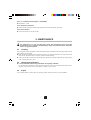
5. MAINTENANCE
Pour la maintenance, utilisez seulement les pièces de rechange qui ont été spécifiées.
Le fabricant ne pourra être tenu pour responsable de tout accident survenu suite à une
réparation effectuée en dehors de son service après-vente ou des réparateurs agréés.
5.1 Entretien
La pince ne doit pas enserrer de câble et être déconnectée de l’appareil de mesure. Ne pas projeter
d’eau sur la pince.
nMaintenir l’entrefer des mâchoires en parfait état de propreté. Enlever les poussières avec un chiffon
doux et sec. De temps en temps, passer un chiffon imprégné d’huile sur les fers pour éviter la
formation de rouille.
nNettoyer le boîtier avec un chiffon légèrement imbibé d’eau savonneuse. Rincer avec un chiffon
humide. Ensuite, sécher rapidement avec un chiffon ou de l’air pulsé à 70°C maxi.
5.2 Vérification métrologique
nComme tous les appareils de mesure ou d’essais, une vérification périodique est nécessaire.
Pour les vérifications et étalonnages de vos appareils, adressez-vous à nos laboratoires de métrologie
accrédités COFRAC ou aux agences MANUMESURE.
Renseignements et coordonnées sur demande :
Tél. : 02 31 64 51 43 Fax : 02 31 64 51 09
5.3 Réparations
Pour les réparations sous garantie et hors garantie, contactez votre agence commerciale Chauvin-
Arnoux la plus proche ou votre centre technique régional Manumesure qui établira un dossier de retour
et vous communiquera la procédure à suivre.
Coordonnées disponibles sur notre site : http://www.chauvin-arnoux.com ou par téléphone aux numéros
suivants : 02 31 64 51 55 (centre technique Manumesure) , 01 44 85 44 85 (Chauvin Arnoux).
Pour les réparations hors de France métropolitaine, sous garantie et hors garantie, retournez l'appareil
à votre agence Chauvin Arnoux locale ou à votre distributeur.

9
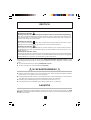
Meaning of symbol
Caution! Please consult the User’s manual before using the device.
In this User’s manual, failure to follow or carry out instructions preceded by this symbol may result in
personal injury or damage to the device and the installations.
Meaning of symbol
This appliance is protected by dual insulation or reinforced insulation. It does not have to be connected
to an earth protection terminal for electrical safety.
Meaning of symbol
Clamp fitted with an electronic output limiter, providing protection against voltage surges caused by
the accidental opening of the clamp’s secondary circuit: 30 V max. peak.
Meaning of CAT III symbol
This voltage surge category III clamp, with pollution level 2, complies with stringent reliability and
availability requirements, corresponding to fixed industrial and domestic installations (see IEC 664-1).
Thank you for purchasing a “C1XX” series ammeter clamp.
To get the best service from this instrument :
nread this user’s manual carefully,
nrespect the safety precautions detailed.
PRECAUTIONS FOR USE
nDo not measure currents greater than 1200 A and limit measuring times above 1000 A (see 4.4.1
Overloads and 4.4.2 Frequencies).
nDo not use the device on non-insulated conductors with a potential of more than 600 V in relation to
the earth and a voltage surge category greater than III.
nComply with environmental conditions (see 4.4.3)
nKeep the gap perfectly clean (see 5.1 Cleaning).
GUARANTEE
Our guarantee is applicable for twelve months after the date on which the equipment is made available
(extract from our General Conditions of Sale, available on request).
ENGLISH

10
CONTENTS
1. Presentation.................................................................................................................................. 10
2. Description................................................................................................................................... 10
3. Use................................................................................................................................................. 11
4. Characteristics............................................................................................................................. 11
4.1 Reference conditions............................................................................................................ 11
4.2 Specifications and references for ordering ......................................................................... 11
4.3 Precision and dephasing ...................................................................................................... 12
4.4 Conditions of use .................................................................................................................. 13
4.5 Dimensions and weight......................................................................................................... 14
4.6 Compliance with international norms ................................................................................... 14
5. Maintenance................................................................................................................................. 15
5.1 Cleaning ................................................................................................................................ 15
5.2 Metrological verification ........................................................................................................ 15
5.3 Repair.................................................................................................................................... 15
6. Appendix ...................................................................................................................................... 37
1. PRESENTATION
The "C100" series clamps are designed to measure alternating currents, on low and medium-powered
installations, from 0.1 A to 1200 A ~ for certain models. See 4. Characteristics).
They can be used on all multimeters, wattmeters, recorders or oscilloscopes for the C160. According to
model (see 4.2) : single or multi-calibre output, alternating current or alternating voltage.
They have dual insulation or reinforced insulation and comply with international norms, particularly
EN 61010-2-032 : 2003 “ammeter clamps”. (See 4.6.)
2. DESCRIPTION
(See drawing in 6. Appendix)
➊Output: Ø 4 mm sockets or lead (according to model) : lead length : 1.5 m and 2 m for the C160.
➋Ratio switch for multi-calibre models.
➌The raised arrow on top of the clamp jaw indicates the direction of the current flow. The current is
considered to flow in the positive direction when it flows from the current producer to the current
consumer. This clamp orientation is necessary when measuring power (measuring current in parallel
with voltage).

11
3. USE
Limit the measuring time between 1000 and 1200 A : 15 minutes on, followed by 30 minutes off.
With the C100 model, which is not protected by an output limiter, do not clamp a conductor before
connecting the clamp to the corresponding measuring device. Likewise, do not disconnect the clamp
from the measuring appliance when the clamp is still attached to the cable.
nBefore connecting the clamp to the multimeter, check that the multimeter has an appropriate calibre.
nOpen the jaws and clamp the cable through which the current you wish to measure is running.
Roughly centre the cable in the jaws. Follow the direction of the arrow, if so required by the application
in question.
nTo read the measurement, apply the appropriate reading coefficient (See 4.2 “Input/output ratio”).
NB : for multi-calibre models, select the ratio which provides the best resolution and precision.
4. CHARACTERISTICS
4.1 Reference conditions
nTemperature : +20... +26°C
nHumidity : 20... 75% RH
nConductor centred in jaws
nSinusoidal current : 48... 65 Hz
nDistortion factor : < 1%
nDirect current : no
nContinuous magnetic field : earth field (< 40 A/m).
nAlternating magnetic field : no
nProximity of external conductors : no current
nMeasuring device impedance
- C100 / C102 / C103 : ≤ 5 Ω- C106 / C107 / C116 / C117 : ≥ 1 MΩ and ≤ 100 pF
- C112 / 113 : ≤ 1 Ω- C160 : ≥ 1 MΩ and ≤ 47 pF
- C122 / C148 : ≤ 0.2 Ω- C173 : ≥ 10 MΩ and ≤ 100 pF
4.2 Specifications and references for ordering
Reference Nominal Ouput
Model for measuring Input/Ouput Connec- protected
ordering scope ratio tion against
voltage surges
Alternating current output
C100 P01.1203.01 100 mA...1000 A Sockets No
C102 P01.1203.02 1 mA~ / 1 A~ Sockets
C112 P01.1203.14 10 mA...1000 A
C103 P01.1203.03 100 mA...1000 A 1 mA~ / 1 A~ Leads 30 V
C113 P01.1203.15 10 mA...1000 A max. peak
C122 P01.1203.06 1 A...1000 A 5 mA~ / 1 A~ Sockets
5 mA~ / 1 A~
C148 P01.1203.07 1 A...1000 A 10 mA~ / 1 A~ Sockets
20 mA~ / 1 A~

12
Reference Nominal
Model for measuring Input/Ouput Connection
ordering scope ratio
Alternating voltage output
C106 P01.1203.04 100 mA... 1000 A 1 mV~ / 1 A~ Sockets
C116 P01.1203.16 10 mA...1000 A
C107 P01.1203.05 100 mA... 1000 A 1 mV~ / 1 A~ Lead
C117 P01.1203.17 10 mA...1000 A
1 A... 1000 A 1 mV~ / 1 A~ Lead
C160 P01.1203.08 100 mA... 100 A 10 mV~ / 1 A~ BNC
100 mA... 10 A 100 mV~ / 1 A~
1 A... 1000 A 1 mV~ / 1 A~
C173 P01.1203.09 100 mA... 100 A 10 mV~ / 1 A~ Lead
10 mA...10 A 100 mV~ / 1 A~
1 mA... 1 A 1000 mV~ / 1 A~
4.3 Precision and dephasing (in reference conditions)
nC100 / C102 / C103 / C106 / C107 : 1000 A calibre
Intensity in A~ 0,1...10 A 10 A 50 A 200 A 1000...1200 A
Intrinsic error (1) ≤ 3% (3) ≤ 3% ≤ 1,5% ≤ 0.75% ≤ 0.5%
Dephasing (2) ≤ 3° ≤ 1.5° ≤ 0.75° ≤ 0.5°
nC112 / C113 / C116 / C117 : calibre 1000 A
Intensity in A~ 10...100 mA 0,1...1 A 1...10 A 10...100 A 100...1200 A
Intrinsic error (1) ≤ 3% (4) ≤ 2% (5) ≤ 1% ≤ 0.5% ≤ 0.3%
Dephasing (2) (2) ≤ 2° ≤ 1° ≤ 0.7°
nC122 / C148 : 1000 A calibre
Intensity in A~ 1...20 A 20 A 50 A 200 A 1000...1200 A
Intrinsic error (1) 6% (6) ≤ 5% ≤ 3% ≤ 1.5% ≤ 1%
Dephasing (2) ≤ 5° ≤ 3° ≤ 1.5° ≤ 1°
nC148 : 500 A calibre
Intensity in A~ 1...10 A 10 A 25 A 100 A 500...600 A
Intrinsic error (1) 6% (7) ≤ 6% ≤ 3% ≤ 2% ≤ 1%
Dephasing (2) ≤ 6° ≤ 4° ≤ 3° ≤ 2.5°
C148 : 250 A calibre
Intensity in A~ 1...5 A 5 A 12,5 A 50 A 250...300 A
Intrinsic error (1) 10% (8) ≤ 10% ≤ 5% ≤ 2% ≤ 2%
Dephasing (2) (2) ≤ 10° ≤ 10° ≤ 10°
(1) As % of output signal (5) + 3 µA for C112 / C113 or + 3 µV for C116 / C117
(2) Unspecified (6) + 0.5 mA
(3) + 0.1 mA for C100 / C102 / C103 or + 0.1 mV for C106 / C107 (7) + 1 mA
(4) + 5 µA for C112 / C113 or + 5 µV for C116 / C117 (8) + 2 mA

13
nC160 : 1000 A calibre (2000 A max. peak)
Intensity in A~ 1...50 A 50...200 A 200...1000 A 1000...1200 A
Intrinsic error (1) ≤ 1% + 1 mV
Dephasing (2) ≤ 3° ≤ 2° ≤ 1°
C160 : 100 A calibre (300 A max. peak)
Intensity in A~ 0.1...5 A 5...20 A 20...100 A 100...120 A
Intrinsic error (1) ≤ 2% + 5 mV
Dephasing (2) ≤ 15° ≤ 10° ≤ 5°
C160 : 10 A calibre (30 A max. peak)
Intensity in A~ 0.1...0.5 A 0.5...2 A 2...10 A 10...12 A
Intrinsic error (1) ≤ 3% + 10 mV
Dephasing (2) (2) ≤ 15° ≤ 15°
(1) As % of output signal (2) Unspecified
nC173 : 1000 A calibre
Intensity in A~ 1...10 A 10...100 A 100...1000 A 1000...1200 A
Intrinsic error (1) ≤ 1% + 0.2 mV ≤ 0,5% + 0.2 mV ≤ 0.2% ≤ 0.2%
Dephasing (2) ≤ 2° ≤ 1° ≤ 1°
C173 : 100 A calibre
Intensity in A~ 0.1...1 A 1...10 A 10...100 A 100...120 A
Intrinsic error (1) ≤ 1% + 0.2 mV ≤ 0.5% + 0.2 mV ≤ 0.3% ≤ 0.2%
Dephasing (2) ≤ 2° ≤ 1° ≤ 1°
C173 : 10 A calibre
Intensity in A~ 0.01...0.1 A 0.1...1 A 1...10 A 10...12 A
Intrinsic error (1) ≤ 1% + 0.2 mV ≤ 0.5% + 0.2 mV ≤ 0.5% ≤ 0.5%
Dephasing (2) ≤ 5° ≤ 2° ≤ 2°
C173 : 1 A calibre
Intensity in A~ 0.001...0.01 A 0.01...0.1 A 0.1...1 A 1...1.2 A
Intrinsic error (1) ≤ 3% + 1 mV ≤ 3% + 1 mV ≤ 0.7% + 1 mV ≤ 0.7% + 1 mV
Dephasing (2) (2) ≤ 10° ≤ 10°
(1) As % of output signal (2) Unspecified
4.4 Conditions of use
The "C100" clamps must be used in the following conditions, in order to comply with user safety and
metrological performance requirements.

14
4.4.1 Overloads
nLimit measuring time above 1000 A.
Intensity I < 1000 A~ 1000 A~ < I < 1200 A~
Operation Permanent (1) 15 minutes on, followed by 30 minutes off.
1) With a frequency F < 1 kHz except C173
C173 with frequency ≤≤
≤≤
≤ 500 Hz :
- Permanent up to 800 A
- Permanent up to 1000 A if temperature ≤ 40°C
- 15 min. on, followed by 30 min. off for 1000 A < I < 1200 A
4.4.2 Frequency
nC100 / C102 / C103 / C106 / C107 / C112 / C113 / C116 / C117 / C122 :
- Use : 30 Hz to 5 kHz
- Current limitation beyond 1 kHz as per following formula :
I permanent = 1000 A
f (in kHz)
nC148 :
- Use : 48 Hz to 1 kHz
nC160 :
- Use : 10 Hz to 100 kHz (-3 dB from 50 kHz to 100 kHz)
- Current limitation beyond 1 kHz as per following formula :
I permanent = 1000 A
f (in kHz)
nC173 :
- Use :10 Hz to 1 kHz for 1000 A calibre
10 Hz to 3 kHz for other calibres
- Current limitation beyond 500 Hz as per following formula :
I permanent = 1000 A
2 x f (in kHz)
4.4.3 Environmental conditions
nIndoor use
nAltitude : < 2000 m
nClimatic conditions : -10 to +55° C and RH < 85%
nAvoid splashing with water
4.5 Dimensions and weight
nOverall dimensions : 216 x 111 x 45 mm
nWeight : approx. 550 g
nJaw opening : 53 mm
nOpen jaw height : 139 mm
nMax. clamping capacity : Ø 52 mm cable or 1 5x5 mm bar or 4 30x5 mm bars
4.6 Compliance with international norms
4.6.1 Electrical safety (as per EN 61010-1 : 2002 and EN 61010-2-032 : 2003)
nDual insulation
nPollution level 2
n600 V Category III

15
4.6.2 EC-compliant electromagnetic compatibility
nEN 61326-1 : 2006
4.6.3 Mechanical protection
nIP40 protection rating (as per IEC 529) with jaws closed and IP30 with jaws open
4.6.4 Auto-extinction
nJaws and housing: V0 (as per UL 94)
5. MAINTENANCE
For maintenance, use only specified spare parts. The manufacturer will not be held
responsible for any accident occuring following a repair done other than by its After Sales
Service or approved repairers.
5.1 Cleaning
The clamp must not be clamped to a cable and must be disconnected from the measuring device. Do not
splash water onto the clamp.
nKeep the jaw gap perfectly clean. Remove dust with a dry, soft cloth. Wipe the iron jaws from time to
time with an oil soaked cloth, in order to prevent rust from forming.
nClean the unit with a cloth and a little soapy water. Rinse with a damp cloth. Then dry quickly with a
cloth or pulsed air at 70°C max.
5.2 Metrological verification
nIt is essential that all measuring instruments are regularly calibrated.
For checking and calibration of your instrument, please contact our accredited laboratories (list on
request) or the Chauvin Arnoux subsidiary or Agent in your country.
5.3 Repair
For all repairs before or after expiry of warranty, please return the device to your distributor.

16
Bedeutung des Zeichens
Achtung ! Beachten Sie vor Benutzung des Gerätes die Hinweise in der Bedienungsanleitung.
Falls die in vorliegender Bedienungsanleitung mit diesem Zeichen gekennzeichneten Anweisungen
nicht beachtet bzw. nicht ausgeführt werden, können körperliche Verletzungen oder Schäden am
Gerät und der Anlage verursacht werden.
Bedeutung des Zeichens
Das Gerät ist schutzisoliert bzw. durch eine verstärkte Isolierung geschützt. Der Anschluß an einen
Erdleiter ist für die Gewährleistung der elektrischen Sicherheit nicht erforderlich.
Bedeutung des Zeichens
Der Ausgang dieser Zangenstromwandler ist mit einer elektronischen Schutzschaltung versehen,
die Überspannungen beim versehentlichen Öffnen des Sekundärkreises der Zange auf max. 30 V
Spitze begrenzt.
Bedeutung des Zeichens CAT III
Der Zangenstromwandler entspricht der Überspannungskategorie III mit einem Verschmutzungsgrad
2 und erfüllt damit die strengen Sicherheits- und Zuverlässigkeitsanforderungen für fest eingebaute
Elektroinstallationen in Industrie und Haushalten (vgl. IEC-Norm 664-1).
Wir bedanken uns bei Ihnen für den Kauf eines Zangenstromwandlers der Serie "C1XX" und das
damit entgegengebrachte Vertrauen. Um die besten Ergebnisse mit Ihrem Meßgerät zu erzielen, bitten
wir Sie :
ndie vorliegende Bedienungsanleitung aufmerksam zu lesen
ndie darin enthaltenen Sicherheitshinweise zu beachten.
SICHERHEITSHINWEISE
nNiemals Ströme über 1200 A messen und bei Strömen über 1000 A die Meßzeit möglichst verkürzen
(siehe Abschn. 4.4.1. Überlast und 4.4.2 Frequenzen).
nDen Zangenstromwandler niemals an nicht isolierten Leitern mit einem Potential von mehr als 600 V
gegenüber Erde und mit einer Überspannungskategorie höher als III benutzen.
nDie zulässigen Umweltbedingungen sind zu beachten (siehe Abschn. 4.4.3).
nDen Zangenspalt stets einwandfrei sauber halten (siehe Abschn. 5.1 Wartung).
GARANTIE
Falls nicht ausdrücklich anders vereinbart, erstreckt sich unsere Garantie auf eine Dauer von zwölf
Monaten ab dem Zeitpunkt der Bereitstellung des Geräts (Auszug aus unseren allg. Verkaufsbedingungen.
Erhältlich auf Anfrage).
DEUTSCH

17
INHALTSVERZEICHNIS
1. Gerätevorstellung......................................................................................................................... 17
2. Gerätebeschreibung................................................................................................................... 17
3. Benutzung ................................................................................................................................... 18
4. Technische Daten........................................................................................................................ 18
4.1 Bezugsbedingungen ............................................................................................................. 18
4.2 Modellbezeichnungen und Bestellangaben ......................................................................... 18
4.3 Meßabweichung und Phasenfehler ..................................................................................... 19
4.4 Betriebsbedingungen............................................................................................................ 20
4.5 Abmessungen, Gewicht ....................................................................................................... 21
4.6 Erfüllung internationaler Normen.......................................................................................... 21
5. Wartung, Pflege ........................................................................................................................... 22
5.1 Reinigung, Pflege .................................................................................................................. 22
5.2 Überprüfung.......................................................................................................................... 22
5.3 Reparatur .............................................................................................................................. 22
6. Anhang ......................................................................................................................................... 37
1. GERÄTEVORSTELLUNG
Die Zangenstromwandler der Serie „C1XX“ dienen zur Messung von Wechselströmen von 0,1 A~ bis
1200 A~ an Anlagen kleiner bis mittlerer Leistung (bestimmte Modelle können ab 1 mA~ messen; siehe
Abschn. 4. Technische Daten).
Die Geräte sind an Multimeter, Wattmeter, Meßwertschreiber usw. bzw. an Oszilloskope anschließbar
(C160). Am Ausgang steht je nach Modell ein Wechselstrom oder eine Wechselspannung zur Verfügung,
ggf. mit Bereichsumschaltung (siehe Abschn. 4.2).
Die Zangenstromwandler sind doppelt bzw. schutzisoliert und entsprechen den internationalen Normen,
insbesondere der EN-Norm 61010-2-032 : 2003 für Zangenstromwandler (siehe Abschn. 4.6).
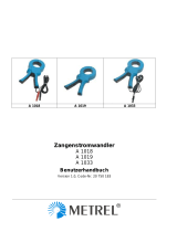
2. GERÄTEBESCHREIBUNG
(siehe Abb. in Abschn. 6. Anhang)
➊Ausgang : Buchsen Ø 4 mm oder Kabel (je nach Modell). Kabellänge 1,5 m bzw. 2 m beim Modell
C160
➋Bereichsumschalter (bei Modellen mit mehreren Meßbereichen)
➌Der oben auf die Zangenbacken eingeprägte Pfeil zeigt die Stromrichtung an. Man geht davon aus,
daß der Strom vom Stromerzeuger zum Stromverbraucher in „positive“ Richtung fließt. Die Flußrichtung
bei Wechselströmen ist nur bei Leistungsmessungen, d.h. gleichzeitiger Messung von Strom und
Spannung, von Bedeutung.

18
3. BENUTZUNG
Bei Strömen zwischen 1000 A und 1200 A die Meßdauer unbedingt einschränken : 15 Minuten Betrieb
und anschließend 30 Minuten Pause.
Beim Modell C100 ist der Ausgang nicht gegen Überspannungen geschützt, daher die Zange immer
zuerst an das Meßgerät anschließen bevor ein Leiter umschlossen wird. Ebenso darf die Zange nicht
vom Meßgerät getrennt werden solange sie noch einen Leiter umschließt.
nVor Anschluß des Zangenstromwandlers prüfen, daß das Multimeter bzw. Meßgerät über einen
geeigneten Meßbereich verfügt.
nZangenbacken öffnen und Leiter mit dem zu messenden Strom umschließen. Leiter in den Backen
möglichst zentrieren und auf Flußrichtung des Stroms achten, falls es die Messung erfordert.
nBei Ablesung des Meßwertes auf das Wandlerverhältnis und den Meßbereich des Multimeters achten
(siehe Abschn. 4.2 „Wandlerverhältnis“).
Hinweis : Bei Modellen mit mehreren Bereichen den Bereich mit der besten Auflösung und Genauigkeit
wählen.
4. TECHNISCHE DATEN
4.1 Bezugsbedingungen
nTemperatur : +20° ... +26°C
nRel. Luftfeuchte : 20% ... 75%
nLeiter liegt zentriert in den Backen
nSinusförmiger Wechselstrom mit : 48... 65 Hz.
nKlirrfaktor : < 1%
nKein Gleichstromanteil
nExternes DC-Magnetfeld : Erdmagnetfeld (< 40 A/m)
nKein externes AC-Magnetfeld
nKeine anderen stromdurchflossenen Leiter in der Nähe
nEingangsimpedanz des Meßgeräts :
- C100 / C102 / C103 : ≤ 5 Ω- C106 / C107 / C116 / C117 : ≥ 1 MΩ und ≤ 100 pF
- C112 / 113 : ≤ 1 Ω- C160 : ≥ 1 MΩ und ≤ 47 pF
- C122 / C148 : ≤ 0,2 Ω- C173 : ≥ 10 MΩ und ≤ 100 pF
4.2 Modellbezeichnungen und Bestellangaben
Wandler- Ausgang
Modell Bestell-Nr Nenn-Meßbereich verhältnis Anschluß Überspannungs-
Ausg./Eing. geschützt
Ausgang : Wechselstrom
C100 P01.1203.01 100 mA... 1000 A Buschen Non
C102 P01.1203.02 1 mA~ / 1 A~ Buschen
C112 P01.1203.14 10 mA...1000 A
C103 P01.1203.03 100 mA... 1000 A 1 mA~ / 1 A~ Kabel 30 Vs max.
C113 P01.1203.15 10 mA...1000 A
C122 P01.1203.06 1 A... 1000 A 5 mA~ / 1 A~ Buschen
5 mA~ / 1 A~
C148 P01.1203.07 1 A... 1000 A 10 mA~ / 1 A~ Buschen
20 mA~ / 1 A~

19
Wandler-
Modell Bestell-Nr Nenn-Meßbereich verhältnis Anschluß
Ausg./Eing.
Ausgang : Wechselspannung
C106 P01.1203.04 100 mA... 1000 A 1 mV~ / 1 A~ Buschen
C116 P01.1203.16 10 mA...1000 A
C107 P01.1203.05 100 mA... 1000 A 1 mV~ / 1 A~ Kabel
C117 P01.1203.17 10 mA...1000 A
1 A... 1000 A 1 mV~ / 1 A~ Kabel mit
C160 P01.1203.08 100 mA... 100 A 10 mV~ / 1 A~ BNC
100 mA... 10 A 100 mV~ / 1 A~
1 A... 1000 A 1 mV~ / 1 A~
C173 P01.1203.09 100 mA... 100 A 10 mV~ / 1 A~ Kabel
10 mA...10 A 100 mV~ / 1 A~
1 mA... 1 A 1000 mV~ / 1 A~
4.3 Meßabweichung und Phasenfehler (unter Bezugsbedingungen)
nC100 / C102 / C103 / C106 / C107 : Bereich 1000 A
Stromstärke in A~ 0,1...10 A 10 A 50 A 200 A 1000...1200 A
Meßabweichung (1) ≤ 3% (3) ≤ 3% ≤ 1,5% ≤ 0,75% ≤ 0,5%
Phasenfehler (2) ≤ 3° ≤ 1,5° ≤ 0,75° ≤ 0,5°
nC112 / C113 / C116 / C117 : Bereich 1000 A
Stromstärke in A~ 10...100 mA 0,1...1 A 1...10 A 10...100 A 100...1200 A
Meßabweichung (1) ≤ 3% (4) ≤ 2% (5) ≤ 1% ≤ 0,5% ≤ 0,3%
Phasenfehler (2) (2) ≤ 2° ≤ 1° ≤ 0,7°
nC122 / C148 : Bereich 1000 A
Stromstärke in A~ 1...20 A 20 A 50 A 200 A 1000...1200 A
Meßabweichung (1) 6% (6) ≤ 5% ≤ 3% ≤ 1,5% ≤ 1%
Phasenfehler (2) ≤ 5° ≤ 3° ≤ 1,5° ≤ 1°
nC148 : Bereich 500 A
Stromstärke in A~ 1...10 A 10 A 25 A 100 A 500...600 A
Meßabweichung (1) 6% (7) ≤ 6% ≤ 3% ≤ 2% ≤ 1%
Phasenfehler (2) ≤ 6° ≤ 4° ≤ 3° ≤ 2,5°
C148 : Bereich 250 A
Stromstärke in A~ 1...5 A 5 A 12,5 A 50 A 250...300 A
Meßabweichung (1) 10% (8) ≤ 10% ≤ 5% ≤ 2% ≤ 2%
Phasenfehler (2) (2) ≤ 10° ≤ 10° ≤ 10°
(1) In % des Ausgangssignals (5) +3 µA bei C112/C113 bzw. +3 µV bei C116/C117
(2) keine Angabe (6) +0,5 mA
(3) +0,1 mA bei C100/C102/C103 bzw. +0,1 mV bei C106/C107 (7) +1 mA
(4) +5 µA bei C112/C113 bzw. +5 µV bei C116/C117 (8) +2 mA

20
nC160 : Bereich 1000 A (2000 A Spitze max.)
Stromstärke in A~ 1...50 A 50...200 A 200...1000 A 1000...1200 A
Meßabweichung (1) ≤ 1% + 1 mV
Phasenfehler (2) ≤ 3° ≤ 2° ≤ 1°
C160 : Bereich 100 A (300 A Spitze max.)
Stromstärke in A~ 0,1...5 A 5...20 A 20...100 A 100...120 A
Meßabweichung (1) ≤ 2% + 5 mV
Phasenfehler (2) ≤ 15° ≤ 10° ≤ 5°
C160 : Bereich 10 A (30 A Spitze max.)
Stromstärke in A~ 0,1...0,5 A 0,5...2 A 2...10 A 10...12 A
Meßabweichung (1) ≤ 3% + 10 mV
Phasenfehler (2) (2) ≤ 15° ≤ 15°
(1) In % des Ausgangssignals (2) keine Angabe
nC173 : Bereich 1000 A
Stromstärke in A~ 1...10 A 10...100 A 100...1000 A 1000...1200 A
Meßabweichung (1) ≤ 1% + 0,2 mV ≤ 0,5% + 0,2 mV ≤ 0,2% ≤ 0,2%
Phasenfehler (2) ≤ 2° ≤ 1° ≤ 1°
C173 : Bereich 100 A
Stromstärke in A~ 0,1...1 A 1...10 A 10...100 A 100...120 A
Meßabweichung (1) ≤ 1% + 0,2 mV ≤ 0,5% + 0,2 mV ≤ 0,3% ≤ 0,2%
Phasenfehler (2) ≤ 2° ≤ 1° ≤ 1°
C173 : Bereich 10 A
Stromstärke in A~ 0,01...0,1 A 0,1...1 A 1...10 A 10...12 A
Meßabweichung (1) ≤ 1% + 0,2 mV ≤ 0,5% + 0,2 mV ≤ 0,5% ≤ 0,5%
Phasenfehler (2) ≤ 5° ≤ 2° ≤ 2°
C173 : Bereich 1 A
Stromstärke in A~ 0,001...0,01 A 0,01...0,1 A 0,1...1 A 1...1,2 A
Meßabweichung (1) ≤ 3% + 1 mV ≤ 3% + 1 mV ≤ 0,7% + 1 mV ≤ 0,7% + 1 mV
Phasenfehler (2) (2) ≤ 10° ≤ 10°
(1) In % des Ausgangssignals (2) keine Angabe
4.4 Betriebsbedingungen
Um die Sicherheit des Benutzers und die meßtechnischen Eigenschaften zu gewährleisten, müssen die
"C1XX“ Zangenstromwandler unter den folgenden Bedingungen betrieben werden.
Seite wird geladen ...
Seite wird geladen ...
Seite wird geladen ...
Seite wird geladen ...
Seite wird geladen ...
Seite wird geladen ...
Seite wird geladen ...
Seite wird geladen ...
Seite wird geladen ...
Seite wird geladen ...
Seite wird geladen ...
Seite wird geladen ...
Seite wird geladen ...
Seite wird geladen ...
Seite wird geladen ...
Seite wird geladen ...
Seite wird geladen ...
Seite wird geladen ...
Seite wird geladen ...
-
 1
1
-
 2
2
-
 3
3
-
 4
4
-
 5
5
-
 6
6
-
 7
7
-
 8
8
-
 9
9
-
 10
10
-
 11
11
-
 12
12
-
 13
13
-
 14
14
-
 15
15
-
 16
16
-
 17
17
-
 18
18
-
 19
19
-
 20
20
-
 21
21
-
 22
22
-
 23
23
-
 24
24
-
 25
25
-
 26
26
-
 27
27
-
 28
28
-
 29
29
-
 30
30
-
 31
31
-
 32
32
-
 33
33
-
 34
34
-
 35
35
-
 36
36
-
 37
37
-
 38
38
-
 39
39


in anderen Sprachen
- français: CHAUVIN ARNOUX CAC113 Manuel utilisateur
- español: CHAUVIN ARNOUX CAC113 Manual de usuario
- italiano: CHAUVIN ARNOUX CAC113 Manuale utente
Andere Dokumente
-
 Chauvin-Arnoux CAMZ02 Bedienungsanleitung
-
 Chauvin-Arnoux CAMZ01 Bedienungsanleitung
-
 METREL EDA1019 Bedienungsanleitung
-
 JB-Lighting Varyscan 5 MV 1200 HMI Benutzerhandbuch
-
ICOM ID-RP4000V Benutzerhandbuch
-
Korg Triton Bedienungsanleitung
-
Ecler M02-99 Benutzerhandbuch
-
Panasonic CQCB9900U - AUTO RADIO/CD DECK Benutzerhandbuch
-
Denon AVR-2311CI Benutzerhandbuch
-
Atmel SAMA5D2-XULT Benutzerhandbuch


