
DEUTSCH
Displacement-Messsensor OD5
für die Stand-Alone-Nutzung ohne Auswerteeinheit
Quickstart
OD5-25x01 OD5-30x05 / OD5-85x20 /
OD5-150x40 / OD5-350W100 /
OD5-500W200
Klasse 1 - Laserprodukt
EN/IEC 60825-1:2014
Exposition vermeiden - Aus die-
ser Önung wird Laserstrahlung
ausgesendet.
Vorsicht - Laserstrahlung - Nicht
in den Strahl blicken.
Maximale Ausgabe: 390μW
Pulsdauer: 6,4ms max.
Wellenlänge: 655nm
Medium: Halbleiterlaser
Klasse 2 Laserprodukt (FDA)
Laserautrittsönung - Exposition
vermeiden - Aus dieser Önung
wird Laserstrahlung ausgesendet.
Laserstrahlung - Nicht in den Strahl
blicken.
Maximale Ausgabe: 1mW
Pulsdauer: 6,4ms max.
Wellenlänge: 655nm
Medium: Halbleiterlaser
Klasse 2 Laserprodukt
(EN/IEC 60825-1:2014)
Vorsicht - Laserstrahlung - Nicht in
den Strahl blicken.
Maximale Ausgabe: 1mW, Puls-
dauer: 6,4ms max., Wellenlänge:
655nm
Medium: Halbleiterlaser
Klasse 2 Laserprodukt
(FDA)
Alle Gerätevarianten: Laserprodukt gemäß JIS C6802/IEC/FDA.
Laserklasse 1, 2 (
ΙΙ). Erfüllt 21 CFR 1040.10 und 1040.11 mit
Ausnahme der aufgeführten Abweichungen im Dokument Laser
Notice No. 50 vom 24. Juni 2007.
Sicherheitshinweise
•
Vor allen Arbeiten den Quickstart lesen.
•
Vorsicht – Wenn andere als die hier angegebenen Bedie-
nungs- oder Justiereinrichtungen benutzt oder andere Ver-
fahrensweisen ausgeführt werden, kann dies zu gefährlicher
Strahlungseinwirkung führen.
VORSICHT
Optische Strahlung Laserklasse 1
Die zugängliche Strahlung stellt bei direkter Betrach-
tung bis zu 100 Sekunden keine Gefahr dar. Mögliche
Gefährdung von Augen und Haut bei nicht bestim-
mungsgemäßer Verwendung.
•
Gehäuse nicht önen. Die Gefahr kann sich durch
das Önen des Gehäuses erhöhen.
•
Gültige nationale Bestimmungen zum Laserschutz
beachten.
VORSICHT
Optische Strahlung Laserklasse 2
Das menschliche Auge ist bei kurzeitiger Bestrahlung
bis zu 0,25 Sekunden nicht gefährdet. Bei längerem
Blick in den Laserstrahl ist eine Schädigung der
Netzhaut möglich. Die Laserstrahlung ist für die men-
schliche Haut ungefährlich.
•
Nicht absichtlich in den Laserstrahl starren.
•
Laserstrahl nicht auf die Augen von Personen richten.
•
Kann ein direkter Blick in den Laserstrahl nicht aus-
geschlossen werden z. B. bei Inbetriebnahme- und
Wartungsarbeiten, geeigneten Augenschutz verwen-
den.
•
Reexionen des Laserstrahls an spiegelnden Ober-
ächen vermeiden. Besonders bei Montage- und Aus-
richtarbeiten darauf achten.
•
Gehäuse nicht önen. Die Gefahr kann sich durch
das Önen des Gehäuses erhöhen.
•
Gültige nationale Bestimmungen zum Laserschutz
beachten.
•
Anschluss, Montage und Einstellung nur durch Fachpersonal.
•
Gerät bei Inbetriebnahme vor Feuchte und Verunreinigung
schützen.
•
Kein Sicherheitsbauteil gemäß EU-Maschinenrichtlinie.
Bestimmungsgemäße Verwendung
Der Displacement-Messsensor OD Precision ist ein optoelek-
tronischer Sensor und wird zur optischen, berührungslosen
Distanzbestimmung von Objekten eingesetzt.
Dieser Quickstart beschreibt den Gebrauch des OD5 Sensorkop-
fes ohne Auswerteeinheit. Weitere Funktionshinweise benden
sich in der OD Precision Betriebsanleitung (8014843).
Inbetriebnahme
Montage
! Aktive Sensoräche parallel zur messenden Objektoberä-
che ausrichten. Dabei Vorzugsrichtung der Sensoren beach-
ten.
" Alle OD5-Sensoren außer OD5-25x01: Bei sehr stark spie-
gelnden Objektoberächen Sensor zur Materialoberäche
neigen (orthogonale Ausrichtung der abgeschrägten Sensor-
äche zur Objektäche) (siehe Abb. D).
§ Abstand der aktiven Sensoräche zur Objektoberäche so
wählen, dass die Messungen möglichst im Zentrum des
Messbereichs erfolgen (siehe Abb. E).
Elektrischer Anschluss
Anschlussleitung anschließen. Biegeradius beachten (siehe
Abb. B).
Kommunikationsbeschreibung
Spezikation der Datenkommunikation (RS-422)
Übertragungscode ASCII (Befehle), Binär (Messwerte)
Datenbits 8
Stoppbits 1
Parität Keine
Steuerzeichen STX, ETX
Checksumme (BCC) XOR
Datenübertragungsrate Einstellbar, siehe Tabelle I
Hinweis: Die Datenübertragungsrate wird nach dem Trennen von
der Versorgungsspannung temporär auf 9,6 kbit/s zurückgesetzt
und nach 5 Sekunden auf die kundenseitig eingestellte Daten-
übertragungsrate umgestellt.
xxxx kbit/s
1)
5 Sekunden
Pow
er on
1)
xxxx kbit/s = kundenseitig eingestellte Datenübertragungsrate
Initialisierung 9,6 kbit/s
3 Sekunden
Automatische Umschaltung
Um jeden kontinuierlichen Messwert ausgeben zu können, ist
folgende minimale Datenübertragungsrate, abhängig vom
eingestellten Messzyklus, erforderlich:
Messzyklus Datenübertragungsrate
100 μs ≥ 909 kbit/s
200 μs ≥ 460,89 kbit/s
400 μs ≥ 230,4 kbit/s
800 μs ≥ 115,2 kbit/s
1.600 μs ≥ 57,6 kbit/s
3.200 μs ≥ 38,4 kbit/s
Unterschreitet die eingestellte Datenübertragungsrate den Tabel-
lenwert, wird nicht jeder interne Messwert über die Schnittstelle
ausgegeben.
Beispiel: Bei der Einstellung „Messzyklus 100 μs“ und „Baudrate
230,4 kbit/s“ wird nur alle 400 μs ein Messwert ausgegeben.
Kommunikationsbefehle und Antworten
Hinweis: 0x_ _ bedeutet hexadezimale, „ “ bedeutet ASCII-Dar-
stellung. Pausenzeit zwischen Befehl und Antwort siehe Tab. H.
Befehle bzw. Antworten haben folgendes Format:
Befehl:
STX Befehl
1)
Daten ETX
Check-
summe
2)
Antwort:
STX Daten 0 Daten 1 Daten 2 ETX
Check-
summe
3)
Generell erfolgt auf jeden gesendeten Befehl eine Antwort.
Es existieren 5 verschiedene Antworttypen.
1) Einzelne Messwertausgabe (Skalierung siehe Abb. F)
STX
High
byte
Middle
byte
Low
byte
ETX
Check-
summe
2) Kontinuierliche Messwertausgabe (Skalierung siehe Abb. F)
STX
High
byte
Middle
byte
Low byte ETX
Check-
summe
STX
High
byte
Middle
byte
Low byte ETX
Check-
summe
usw.
3) Bestätigung einer erfolgreichen Parameteränderung
STX „>“ „ “ „ “ ETX
Check-
summe
4) Ausgabe eines aktuell eingestellten Parameters
STX Daten
1)
„.“ „.“ ETX
Check-
summe
5) Fehlermeldung bei nicht erkannten Befehlen
STX „?“ „.“ „.“ ETX
Check-
summe
1) Siehe Tabelle I „Kommunikationsbefehle“.
2) Befehl XOR Daten XOR ETX.
3) Daten 0 XOR Daten1 XOR Daten2 XOR ETX.
Beispiele zu den 5 Antworttypen
1) Befehl: Anforderung einzelner Messwert
0x02 „M“ „?“ 0x03 0x71
Antwort OD5 (Beispiel: Messwert = unteres Messbereichsende =
55555 (Hex)); (Skalierung siehe Abb. F )
0x02 M „?“ 0x03 0x71 0x06
2) Befehl: Start kontinuierliche Messwertausgabe
0x02 „M“ „1“ 0x03 0x7F
Antwort OD5 (Beispiel: Messwert = unteres Messbereichsende =
55555 (Hex)); (Skalierung siehe Abb. F)
0x02 0x05 0x55 0x55 0x03 0x06
0x02 0x05 0x55 0x55 0x03 0x06
usw.
3) Befehl: Parameteränderung Mittelungstiefe = 512 Messwerte
0x02 „A“ „9“ 0x03 0x7B
Antwort OD5 nach erfolgreicher Parameteränderung
0x02 „>“ „ “ „ “ 0x03 0x3D
4) Befehl: Parameterabfrage „Mittelungstiefe?“
0x02 „A“ „?“ 0x03 0x7D
Antwort OD5 auf Abfrage der Mittelungstiefe.
(„9“ entspricht 512 Messwerten)
0x02 „9“ „ “ „ “ 0x03 0x3A
5) Antwort OD5 bei nicht erkanntem Befehl
0x02 „?“ „ “ „ “ 0x03 0x3C
Laser-o-Eingang
Sie können den Laser über den Eingang „Laser o“ (Pin 12,
weiß) ein- und ausschalten.
Synchro-Eingang
Zur Vermeidung von gegenseitiger Beeinussung zweier Senso-
ren können diese bei aktiviertem Parameter „Anti interference“
über den Eingang „Synchro“ (Pin 11, grau) auf ein externes
Triggersignal alternierend getriggert werden.
Das Triggersignal zeigt folgenden zeitlichen Verlauf:
AA
A A
B
C
C
Sensor
1
ON
OFF
Sensor
2
ON
OFF
Messzyklus: 100 μs Messzyklus: 800 μs
A 50 μs 50 μs
B 300 μs 2.400 μs
C 600 μs 4.800 μs
Eingangssignale (NPN oder PNP)
Für die Eingänge „Laser-o“ und „Syncro“ stellen Sie über den
Befehl „Eingang“ den Typ als „NPN“ oder „PNP“ ein. Der Typ legt
den notwendigen Pegelzustand fest.
NPN PNP
Laser o 0 V 12 … 24 V DC
Laser on 12 … 24 V DC oder oen 0 V oder oen
Wartung
Es wird empfohlen in regelmäßigen Abständen die optischen
Grenzächen zu reinigen und Verschraubungen, sowie Steckver-
bindungen zu prüfen.
OD5- 25T01 25W01 30T05 30W05 85T20 85W20 150T40
*)
150W40
*)
350W100 500W200
Artikelnummer 6035975 6035976 6035977 6035978 6035979 6035980 6049579 6049580
6035981 6035982
Messbereich
1)
24 … 26 mm 25 … 35 mm 65 … 105 mm 110 … 190 mm 250 … 450 mm 300 … 700 mm
Wiederholgenauigkeit
2) 3)
0,02 μm 0,2 μm 1 μm 2 µm 5 μm 10 μm
Linearität
2)
± 1,6 μm ± 8 μm ± 20 μm ± 40 μm ± 160 μm ± 400 μm
Messfrequenz ≤ 10 kHz ≤ 10 kHz ≤ 10 kHz ≤ 10 kHz ≤ 1,25 kHz ≤ 1,25 kHz
Ansprechzeit
4)
≥ 0,1 ms ≥ 0,1 ms ≥ 0,1 ms ≥ 0,1 ms ≥ 0,8 ms ≥ 0,8 ms
Lichtsender Laser, rot
Laserklasse
5)
1 (EN 60825 1) / 2 (FDA) 2 (EN 60825 1) / 2 (FDA)
Typ. Lichteck abmessung
(Distanz)
25 μm x 35 μm
(25 mm)
100 μm x 700 μm
(25 mm)
30 μm x 100 μm
(30 mm)
0,26 mm x 1 mm
(30 mm)
70 mm x 290 μm
(85 mm)
0,26 mm x 1,2 mm
(85 mm)
ø 180 µm
(150 mm)
0,33 x 1,60 mm
(150 mm)
0,7 mm x 2,4 mm
(350 mm)
1,0 mm x 3,7
mm (500 mm)
Schnittstelle RS-422
Versorgungs-
spannung U
V
12 … 24 V DC (–5/+10 %)
Leistungsaufnahme max. 1,8 W
Aufwärmzeit ≤ 5 min
Material Gehäuse: Aluminium, Linse: Glas
Anschluss Leitung, Leitungslänge: 0,5 m, Leitungsdurchmesser: 7mm, Stecker, 12-polig, mit separater Leitung auf 50 m erweiterbar
Gewicht 250 g inkl. 0,5 m Kabel
Schutzart IP 67
Schutzklasse III
Umgebungs-
bedingungen
Betrieb: –10 … +50 °C bei rel. Feuchte 35 % ... 85 % (nicht kondensierend);
Lagerung: –20 … +60 °C
Fremdlichtsicherheit Künstliches Licht:
≤ 3.000 lx; Sonnenlicht: ≤ 10.000 lx
Temperaturdrift 0,01 % FS (FS: Full Scale: Messbereich des Sensors)
Vibrationsfestigkeit 10 … 55 Hz (Amplitude 1,5 mm; x-, y- und z-Achse jeweils 2 Stunden)
Stoßfestigkeit 50 G (x-, y- und z-Achse jeweils 3 Mal)
Zusätzliche Funktionen Mittelwertsbildung: 1 … 4,096x; Messfrequenz wählbar; Automatische/Manuelle Einstellung der Empndlichkeit; Anti-Interference-Mode; Glassdickenmessung
1)
6...90° Remissionsgrad.
2)
Messung auf 90 % Remissionsgrad (Keramik, weiß), bzw. Spiegel für OD5-25x.
3)
Gewählte Mittelwerteinstellung: 256 bzw. 4096 für OD5-25x; konstante Rahmenbedingungen.
4)
Benötigte Zeit für automatische Anpassung der Empndlichkeit errechnet sich aus: Sampling period x 20. Bei Standardeinstellung 100µs (10kHz) entspricht
dies <= 2 ms, bei 800µs (1,25kHz) entspricht dies <= 16ms (OD5-350x und OD5-500x).
5)
Klasse 1: Wellenlänge 650 nm, max. Leistung: 390 μW; Klasse 2: Wellenlänge 650 nm, max. Leistung: 1 mW.
*)
Kompatibel mit Auswerteeinheit AOD5 Hardwareversion ab 1.7, und Softwareversi-
on ab 4.3 (entspricht Produktionszeitraum ab Lot.1338)
Befehl
(ASCII)
Daten
(ASCII)
Beschreibung
Measure/
Messung
M 0 Stop continual output of measurement
value
1 Start continual output of measurement
value
? Request one time output of measurement
value
Baud rate/
Datenüber-
tragungsrate
B 0 Set baud rate to 9,6 kbit/s
1 Set baud rate to 19,2 kbit/s
2 Set baud rate to 38,4 kbit/s
3
Set baud rate to 57,6 kbit/s
1)
4
Set baud rate to 115,2 kbit/s
1)
5
Set baud rate to 230,4 kbit/s
1)
6
Set baud rate to 460,8 kbit/s
1)
7
Set baud rate to 909,0 kbit/s
1)
8
Set baud rate to 1.875 kbit/s
1)
9 Set baud rate to 312,5 kbit/s
A Set baud rate to 625,0 kbit/s
B Set baud rate to 1.250,0 kbit/s
? Request actual baud rate setting
Averaging/
Mittlungs-
tiefe
A 0 Set Averaging to 1
1 Set Averaging to 2
2 Set Averaging to 4
3 Set Averaging to 8
4 Set Averaging to 16
5 Set Averaging to 32
6 Set Averaging to 64
7 Set Averaging to 128
8 Set Averaging to 256
9 Set Averaging to 512
A Set Averaging to 1024
B Set Averaging to 2048
C Set Averaging to 4096
? Request actual averaging setting
Alarm D 0 Set behavior in case of failed
measurement to Clamp
1 Set behavior in case of failed
measurement to Hold
? Request active setting for behavior in case
of failed measurement
Sampling
period/
Messzyklus
C
0
2)
Set sampling period to 100 μs
1 Set sampling period to 200 μs
2 Set sampling period to 400 μs
3
2)
Set sampling period to 800 μs
4 Set sampling period to 1600 μs
5 Set sampling period to 3200 μs
6 Set sampling period to automatic
? Request actual sampling period
Laser power/
Laser-
leistung
L 0 Switch o laser
1 Set laser power to 1 (Min.)
2 Set laser power to 2
3 Set laser power to 3
4 Set laser power to 4
5 Set laser power to 5 (Max.)
? Request actual laser power setting
Thresh level/
Trigger-
schwelle
T 0 Set thresh level to 0 (Min.)
1 Set thresh level to 1
… ...
E Set thresh level to 14 (Max.)
F Set thresh level to automatic control
? Request actual thresh level setting
Sensitivity/
Empnd-
lichkeit
S 0 Set sensitivity to Min.
1 Set sensitivity to 1
2 Set sensitivity to 2
… …
9 Set sensitivity to 9
A Set sensitivity to Max.
B Set sensitivity to automatic control
? Request actual setting for sensitivity
Target/
Messmodus
R 0 Set measurement target to surface
1 Set measurement target to background/
rear
2 Set measurement target to glass thickness
3 Set measurement target to glass gap
? Request actual measuring mode
Alignment/
Ausrichtung
4)
V 0 Set alignment to standard/diuse
1 Set alignment to tilted/specular (siehe D)
? Request actual alignment setting
Anti-
Interference
I 0 De-activate anti interference mode
1 Activate anti interference mode
? Request actual anti interference setting
Input/
Eingang
N 0 Set input behavior to PNP
1 Set input behavior to NPN
? Request actual input behavior setting
1)
Datenrate des Sensors weicht teilweise von den üblichen Standarddatenraten
ab.
2)
OD5-25, OD5-30, OD5-85, OD5-150: 100 μs.
3)
OD5-350, OD5-500: 800 μs.
4)
Nur für OD5-30, OD5-85 verfügbar.
I
Kommunikationsbefehle
Datenübertragungsrate Pausenzeit
9,6 kbit/s 52,70 μs
19,2 kbit/s 37,90 μs
38,4 kbit/s 13,40 μs
57,6 kbit/s 9,00 μs
115,2 kbit/s 4,65 μs
230,4 kbit/s 2,47 μs
312,5 kbit/s 1,91 μs
460,8 kbit/s 1,41 μs
625,0 kbit/s 1,11 μs
909,0 kbit/s 0,87 μs
1.250,0 kbit/s 0,70 μs
1.875,0 kbit/s 0,60 μs
H
Pausenzeit zwischen Befehl und Antwort
C
Ausrichtung
D
Ausrichtung bei stark spiegelnden Oberächen
Unteres
Messbereichsende
1FFFFF
1AAAAA
100000
55555
Messwert
in Hex
Oberes
Messbereichsende
Messbereichs-
mitte
Distanz
F
Messwertskalierung
Der Messwert wird als HEX-Wert übertragen. Jeder Sensor wird
in einem Bereich von 55555 [Hex] bis 1AAAAA [Hex] skaliert.
OD5- 25x01 30x05 Hex Dezimal
Oberes Messbereichsende 26 mm 35 mm 1AAAAA 1747626
Unteres Messbereichsende 24 mm 25 mm 55555 349525
Messbereich
1)
2 mm 10 mm 1398101
1) Messbereich = Oberes Messbereichsende – Unteres Messbereichsende
Gehen Sie wie folgt vor:
1. Messwert [Hex] in Messwert [Dezimal] umrechnen.
2. Messwert [Dezimal] in Messwert [mm] umrechnen.
Formel für Umrechnung Messwert in mm
(Messwert [Dez] – Unteres Messbereichsende [Dez]) X
(Messbereich [mm] / Messbereich [Dez]) +
Unteres Messbereichsende [mm] = Messwert [mm]
Beispiel: OD5-25T01, Ausgabe Messwert: 122222 [Hex]
1. Messwert [Dez]: 1188386 [Dez]
2. Messwert [mm]:
(1188386 [Dez] – 349525 [Dez]) X (2 [mm] / 1398101 [Dez])
+ 24 [mm] = 25.2 [mm]
G
Umrechnung Messwert von HEX-Wert in Dezimal-Wert
1 nicht belegt
nc
RX+
RX–
M
L+
TX+
nc
5
6
8
yel
blk
Ø 1.2
ora
blu
brn
red
1
2
4
3
TX–
7
Shield
9
blk
nc
10
Syncro
11
gra
Laser of
f
12
wht
Ø 1.8
1
1
1
Min. 30 mm
Radius
M
inimum 30 mm
Elektrischer Anschluss
B
8013569/195S/2020-09/8M_PK
OD Precision
Australia
Phone +61 (3) 9457 0600
1800 33 48 02 –
tollfree
Austria
Phone +43 (0) 2236 62288-
0
Belgium/Luxembourg
Phone +32 (0) 2 466 55 66
Brazil
Phone +55 11 3215-4900
Canada
Phone +1 905.771.1444
Czech Republic
Phone +420 234 719 500
Chile
Phone +56 (2) 2274 7430
China
Phone +86 20 2882 3600
Denmark
Phone +45 45 82 64 00
Finland
Phone +358-9-25 15 800
France
Phone +33 1 64 62 35 00
Germany
Phone +49 (0) 2 11 53 010
Greece
Phone +30 210 6825100
Hong Kong
Phone +852 2153 6300
Hungary
Phone +36 1 371 2680
India
Phone +91-22-6119 8900
Israel
Phone +972 97110 11
Italy
Phone +39 02 27 43 41
Japan
Phone +81 3 5309 2112
Malaysia
Phone +603-8080 7425
Mexico
Phone +52 (472) 748 9451
Netherlands
Phone +31 (0) 30 229 25 44
New Zealand
Phone +64 9 415 0459
0800 222 278 –
tollfree
Norway
Phone +47 67 81 50 00
Poland
Phone +48 22 539 41 00
Romania
Phone +40 356-17 11 20
Russia
Phone +7 495 283 09 90
Singapore
Phone +65 6744 3732
Slovakia
Phone +421 482 901 201
Slovenia
Phone +386 591 78849
South Africa
Phone +27 10 060 0550
South Korea
Phone +82 2 786 6321/4
Spain
Phone +34 93 480 31 00
Sweden
Phone +46 10 110 10 00
Switzerland
Phone +41 41 619 29 39
Taiwan
Phone +886-2-2375-6288
Thailand
Phone +66 2 645 0009
Turkey
Phone +90 (216) 528 50 00
United Arab Emirates
Phone +971 (0) 4 88 65 878
United Kingdom
Phone +44 (0)17278 31121
USA
Phone +1 800.325.7425
Vietnam
Phone +65 6744 3732
Irrtümer und Änderungen vorbehalten
BZ int49
Detailed addresses and further locations at www.sick.com
entsprechend Geräteaufdruck
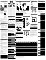
E
Anzeige LED Distance
± 5 % des Messbereichs
Fern
Messbereichs-
mitte
LED blinkt
Rot/Grün
LED Distance
LED blinkt
Rot/Grün
Außerhalb
Me
ssbereich
Außerhalb
Messbereic
h
Grün Orange Rot
Nah
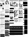
A
Displacement-
Sensor
DISTANCE
LASER ON
Au
fbau und Geräteabmessungen, Maßeinheit: mm (inch), Dezimaltrennzeichen: Punkt
M4
OD5-25x01
C
A
B
OD5-30x05
OD5-85x20
OD5-150x40
OD5-350W100
OD5-500W200
Optische Achse – Sender
Anschlussleitung
Optische
Achse – Lichtfleck (bei 25 mm wegen V-Optik mit 17,5°)
LED Distance (Abstandsanzeige)
LED Laser on
Optische Achse – Empfänger
25.6
(1.01)
32.1
(1.26)
40 (1.57)
47.9 (1.89)
1.5 (0.06)
4.2 (0.17)
76.5 (3.01)
75 (2.95)
78 (3.07)
Ø 7.1
(0.28)
4.2
(0.17)
A [mm (inch)]
OD5-30x05 19.1
(0.75)
OD5-85x20 19.1
(0.75)
OD5-150x40 19.1 (0.75)
OD5-350W100 19.1 (0.75)
B [mm (inch)]
33.1
(1.30)
41.9 (1.65)
46.9 (1.85)
48.5 (1.91)
OD5-500W200 19.1 (0.75) 49.7 (1.96)
C [mm (inch)]
27.0
(1.06)
27.0 (1.06)
27.0 (1.06)
25.6 (1.01)
25.6 (1.01)

ENGLISH
Displacement measurement sensor OD5
for stand-alone use without controller unit
Quickstart
OD5-25x01 OD5-30x05 / OD5-85x20 /
OD5-150x40 / OD5-350W100 /
OD5-500W200
Class 1 - Laser product
EN/IEC 60825-1:2014
Avoid exposure - Laser radiation is
emitted from this aperture.
Caution - Laser radiation - Do not
stare into beam.
Maximum output: 390μW
Pulse duration: 6,4ms max.
Wave length: 655nm
Medium: semiconductor laser
Class 2 Laser product (FDA)
Laser aperture - Avoid exposure
-
Laser radiation is emitted from
this aperture
.
Laser radiation - Do not stare into
beam.
Maximum output: 1mW
Pulse duration: 6,4ms max.
Wave length: 655nm
Medium: semiconductor laser
Class 2 Laser product
(EN/IEC 60825-1:2014)
Caution - Laser radiation - Do not
stare into beam.
Maximum output: 1mW, Pulse
duration: 6,4ms max., Wave
length: 655nm
Medium: semiconductor laser
Class 2 Laser product
(FDA)
All device variants: Laser product in accordance with JIS C6802/
IEC/FDA. Laser class 1, 2 (ΙΙ). Complies with 21 CFR 1040.10 and
1040.11 except for the listed tolerances in the document “Laser
Notice No. 50, dated June 24, 2007.
Safety notes
•
Read the Quickstart before performing any work.
•
Caution – Use of controls or adjustments or performance
of procedures other than those specied herein may re-
sult in hazardous radiation exposure.
CAUTION
Optical radiation: Laser class 1
The accessible radiation does not pose a danger when
viewed directly for up to 100 seconds. It may pose a
danger to the eyes and skin in the event of incorrect
use.
•
Do not open the housing. Opening the housing may
increase the level of risk.
•
Current national regulations regarding laser protec-
tion must be observed.
CAUTION
Optical radiation: Laser class 2
The human eye is not at risk when briey exposed to
the radiation for up to 0.25 seconds. Exposure to the la-
ser beam for longer periods of time may cause damage
to the retina. The laser radiation is harmless to human
skin.
•
Do not look into the laser beam intentionally.
•
Never point the laser beam at people’s eyes.
•
If it is not possible to avoid looking directly into the
laser beam, e.g., during commissioning and mainte-
nance work, suitable eye protection must be worn.
•
Avoid laser beam reections caused by reective sur-
faces. Be particularly careful during mounting and
alignment work.
•
Do not open the housing. Opening the housing may
increase the level of risk.
•
Current national regulations regarding laser protection
must be observed.
•
Connection, mounting and setting must be performed by
qualied personnel.
•
Protect devices from moisture and contamination during
commissioning.
•
No safety component pursuant to EU directive.
Intended use
The displacement measurement sensor OD Precision is an opto-
electronic sensor and is used for optical determination of object
distances without contact.
This Quickstart describes the use of the OD5 sensor header
without controller unit. Additional operating instructions are in
the OD Precision Operating Instructions (8014844).
Commissioning
Mounting
! Align the active sensor surface parallel to the object surface
to be measured. Note the preferred direction of the sensors.
" All OD5 sensors except OD5-25x01: If object surface is high-
ly reective, tilt slightly to the material surface (orthogonal
alignment of the angular sensor surface to the object sur-
face) (see Fig. D).
§ Select the distance of the active sensor surface, so that the
measurements are taken in the middle of the measurement
range (see Fig. E).
Electrical installation
Connect connecting cable. Note bending radius (see Fig. B).
Communication description
Specications of data communication (RS-422)
Transmission code ASCII (commands),
Binary (measuring values)
Data bits 8
Stop bits 1
Parity None
Control character STX, ETX
Check sum (BCC) XOR
Data transmission rate Adjustable, see Table I
Note: The data transmission rate is temporarily reset to
9.6 kbit/s after the supply voltage is disconnected and after
5 seconds it is changed back to the data transmission rate
previsouly set by the customer.
xxxx kbit/s
1)
5 seconds
Pow
er on
1)
xxxx kbit/s = Data transmission rate set by the customer
Initialization 9.6 kbit/s
3 seconds
Automatic switching
To be able to output each measurement value taken continually,
the following minimum data transmission rate is required for the
dierent sampling period settings.
Sampling period Data transmission rate
100 μs ≥ 909 kbit/s
200 μs ≥ 460,89 kbit/s
400 μs ≥ 230,4 kbit/s
800 μs ≥ 115,2 kbit/s
1.600 μs ≥ 57,6 kbit/s
3.200 μs ≥ 38,4 kbit/s
If the set data transmission rate falls short of the table value,
not each internal measurement value is output via the interface.
Example: At the sampling period setting of “100 μs” and baud
rate “230.4 kbit/s”, a measurement value is only output every
400 μs.
Communication commands and responses
Note: 0x_ _ signies a hexadecimal display, and “ “ signies an
ASCII display. Interval time between command and response see
Tab. H. Commands or responses have the following format:
Command:
STX
Com-
mand
1)
Data ETX
Check-
sum
2)
Response:
STX Data 0 Data 1 Data 2 ETX
Check-
sum
3)
There is generally a response to a sent command.
Five response types exist.
1) Single output of measurement values (for scaling, see F)
STX High byte
Middle
byte
Low byte ETX
Check-
sum
2) Continual output of measurement values (for scaling, see. F)
STX High byte
Middle
byte
Low byte ETX
Check-
sum
STX High byte
Middle
byte
Low byte ETX
Check-
sum
etc.
3) Conrmation of a successful parameter change
STX “>” “ “ “ “ ETX
Check-
sum
4) Output of a currently set parameter
STX Data
1)
“.” “.” ETX
Check-
sum
5) Error message when commands are not recognized
STX “?” “.” “.” ETX
Check-
sum
1) See Table I “Communication commands”.
2) Command XOR Data XOR ETX.
3) Data 0 XOR Data 1 XOR Data 2 XOR ETX.
Examples of the 5 response types
1) Command: Request for a single measurement value
0x02 “M” “?” 0x03 0x71
Response OD5 (example: measurement value = near end of
measuring range = 55555 (Hex)); (for scaling, see. F)
0x02 M “?” 0x03 0x71 0x06
2) Command: Start continual measurement value output
0x02 “M” “1” 0x03 0x7F
Response OD5 (example: measurement value = near end of
measuring range = 55555 (Hex)); (for scaling, see F)
0x02 0x05 0x55 0x55 0x03 0x06
0x02 0x05 0x55 0x55 0x03 0x06
etc.
3) Command: Parameter change of averaging function =
512 measurement values
0x02 “A” “9” 0x03 0x7B
Response OD5 after successful parameter change
0x02 “>” “ “ “ “ 0x03 0x3D
Com-
mand
(ASCII)
Data
(ASCII)
Description
Measure M 0 Stop continual output of measurement
value
1 Start continual output of measurement
value
? Request one time output of measurement
value
Baud rate B 0 Set baud rate to 9.6 kbit/s
1 Set baud rate to 19.2 kbit/s
2 Set baud rate to 38.4 kbit/s
3
Set baud rate to 57.6 kbit/s
1)
4
Set baud rate to 115.2 kbit/s
1)
5
Set baud rate to 230.4 kbit/s
1)
6
Set baud rate to 460.8 kbit/s
1)
7
Set baud rate to 909.0 kbit/s
1)
8
Set baud rate to 1,875.0 kbit/s
1)
9 Set baud rate to 312.5 kbit/s
A Set baud rate to 625.0 kbit/s
B Set baud rate to 1,250.0 kbit/s
? Request actual baud rate setting
Averaging A 0 Set Averaging to 1
1 Set Averaging to 2
2 Set Averaging to 4
3 Set Averaging to 8
4 Set Averaging to 16
5 Set Averaging to 32
6 Set Averaging to 64
7 Set Averaging to 128
8 Set Averaging to 256
9 Set Averaging to 512
A Set Averaging to 1024
B Set Averaging to 2048
C Set Averaging to 4096
? Request actual averaging setting
Alarm D 0 Set behavior in case of failed
Measurement to Clamp
1 Set behavior in case of failed
measurement to Hold
? Request active setting for behavior in case
of failed measurement
Sampling
period
C
0
2)
Set sampling period to 100 μs
1 Set sampling period to 200 μs
2 Set sampling period to 400 μs
3
2)
Set sampling period to 800 μs
4 Set sampling period to 1600 μs
5 Set sampling period to 3200 μs
6 Set sampling period to automatic
? Request actual sampling period
Laser power L 0 Switch o laser
1 Set laser power to 1 (Min.)
2 Set laser power to 2
3 Set laser power to 3
4 Set laser power to 4
5 Set laser power to 5 (Max.)
? Request actual laser power setting
Thresh level T 0 Set thresh level to 0 (Min.)
1 Set thresh level to 1
… ...
E Set thresh level to 14 (Max.)
F Set thresh level to automatic control
? Request actual thresh level setting
Sensitivity S 0 Set sensitivity to Min.
1 Set sensitivity to 1
2 Set sensitivity to 2
… …
9 Set sensitivity to 9
A Set sensitivity to Max.
B Set sensitivity to automatic control
? Request actual setting for sensitivity
Target R 0 Set measurement target to surface
1 Set measurement target to background/
rear
2 Set measurement target to glass thickness
3 Set measurement target to glass gap
? Request actual measuring mode
Alignment
4)
V 0 Set alignment to standard/diuse
1 Set alignment to tilted/specular (see D)
? Request actual alignment setting
Anti-
Interference
I 0 De-activate anti interference mode
1 Activate anti interference mode
? Request actual anti interference setting
Input N 0 Set input behavior to PNP
1 Set input behavior to NPN
? Request actual input behavior setting
1)
Some of the available baud rates dier from typical standard baud rates.
2)
OD5-25, OD5-30, OD5-85, OD5-150: 100 μs.
3)
OD5-350, OD5-500: 800 μs.
4)
Only available for OD5-30, OD5-85.
I
Communication commands
C
Alignment
D
Alignment for highly reective surfaces
Near end
of measuring
range
1FFFFF
1AAAAA
100000
55555
Measured
value
in Hex
Far end of
measuring
range
Middle of
measuring
range
Distance
F
Measurement value scaling
OD5- 25T01 25W01 30T05 30W05 85T20 85W20 150T40
*)
150W40
*)
350W100 500W200
Part number 6035975 6035976 6035977 6035978 6035979 6035980 6049579 6049580
6035981 6035982
Measuring range
1)
24 … 26 mm 25 … 35 mm 65 … 105 mm 110 … 190 mm 250 … 450 mm 300 … 700 mm
Repeatability
2) 3)
0.02 μm 0.2 μm 1 μm 2 µm 5 μm 10 μm
Linearity
2)
± 1.6 μm ± 8 μm ± 20 μm ± 40 μm ± 160 μm ± 400 μm
Measuring frequency ≤ 10 kHz ≤ 10 kHz ≤ 10 kHz ≤ 10 kHz ≤ 1,25 kHz ≤ 1,25 kHz
Response time
4)
≥ 0.1 ms ≥ 0.1 ms ≥ 0.1 ms ≥ 0.1 ms ≥ 0.8 ms ≥ 0.8 ms
Light sender Laser, red
Laser protection class
5)
1 (EN 60825 1) / 2 (FDA) 2 (EN 60825 1) / 2 (FDA)
Typ. light spot size
(distance)
25 μm x 35 μm
(25 mm)
100 μm x 700 μm
(25 mm)
30 μm x 100 μm
(30 mm)
0.26 mm x 1 mm
(30 mm)
70 mm x 290 μm
(85 mm)
0.26 mm x 1.2 mm
(85 mm)
ø 180 µm
(150 mm)
0.33 x 1,60 mm
(150 mm)
0.7 mm x 2,4 mm
(350 mm)
1.0 mm x 3.7 mm
(350 mm)
Data interface RS-422
Supply voltage V
S
12 … 24 V DC (–5/+10 %)
Power consumption max. 1.8 W
Warm up time ≤ 5 min
Material Housing: Aluminum, Lens: Glass
Connection Cable, length of cable: 0.5 m, cable diameter: 7 mm, male connector, 12-pin, can be extended to 50 m with separate cable
Weight 250 g incl. 0.5 m cable
Enclosure rating IP 67
Protection class III
Ambient condition Operation: –10 … +50 °C at relative humidity 35 % ... 85 % (not condensing);
Storage: –20 … +60 °C
Ambient light safety Articial light:
≤ 3.000 lx; Sunlight: ≤ 10.000 lx
Temperature drift 0.01 % FS (FS: Full Scale: Measuring range of sensor)
Vibration resistance 10 … 55 Hz (amplitude 1.5 mm; x-, y- and z-axis 2 hours each)
Shock resistance 50 G (x-, y- and z-axis 3 times)
Additional functions Averaging function: 1 … 4.096x; measuring frequency selectable; automatic/manual sensitivity adjustment; anti-interference mode; glass thickness measurement
1)
6...90° radiance factor.
2)
Measurement at 90% radiance factor (ceramic, white) or mirror for OD5-25x.
3)
Selected mean value setting: 256 or 4096 for OD5-25x; constant framework conditions.
4)
Required time for automated adjustment of the sensitivity is calculated as follows: Sampling period x 20. With default setting 100 µs (10 kHz), this corre-
sponds to <= 2 ms, at 800 µs (1.25 kHz), this corresponds to <= 16 ms (OD5-350x and OD5-500x).
5)
Class 1: wavelength 650 nm, max. power: 390 μW; Class 2: wavelength 650 nm, max. power: 1 mW.
*)
Compatible with controller unit AOD5 hardware version 1.7. and software version 4.3
(correspond with production date from Lot 1338)
Data transmission rate Interval time
9.6 kbit/s 52.70 μs
19.2 kbit/s 37.90 μs
38.4 kbit/s 13.40 μs
57.6 kbit/s 9.00 μs
115.2 kbit/s 4.65 μs
230.4 kbit/s 2.47 μs
312.5 kbit/s 1.91 μs
460.8 kbit/s 1.41 μs
625.0 kbit/s 1.11 μs
909.0 kbit/s 0.87 μs
1,250.0 kbit/s 0.70 μs
1,875.0 kbit/s 0.60 μs
H
Interval time between command and response
± 5 % of measuring range
Far
Middle of
measuring range
LED flashes
red/green
LED Distance
LED flashes
red/green
Outside
measuring rang
e
Outside
measuring rang
e
Green Orange Red
Near
E
Indicator Distance LED
4) Command: Parameter query „Averaging function?“
0x02 “A” “?” 0x03 0x7D
Response OD5 on parameter query averaging function.
(“9” equates to 512 measurement values)
0x02 “9” “ “ “ “ 0x03 0x3A
5) Response OD5 on non-recognized command
0x02 „?“ „ “ „ “ 0x03 0x3C
Laser-o-Input
The laser can be switched on or o via the input “Laser o” (pin
12, white).
Synchronous input
To prevent mutual interference, the two sensors can be triggered
alternatingly by an external trigger signal via the input “Synchro”
(pin 11, gray) when the the parameter “Anti interference” is
activated.
The trigger signal shows the following temporal sequence:
AA
A A
B
C
C
Sensor
1
ON
OFF
Sensor
2
ON
OFF
Sampling period: 100 μs Sampling period: 800 μs
A 50 μs 50 μs
B 300 μs 2.400 μs
C 600 μs 4.800 μs
Input signals (NPN or PNP)
The command “Input” is used to set the Inputs “Laser-o” and
“Synchro” to “PNP” type or “NPN” type. The type species the
required level status.
NPN PNP
Laser o 0 V 12 … 24 V DC
Laser on 12 … 24 V DC or open 0 V or open
Maintenance
It is recommended to regularly clean the external lens surfaces
and to check screw connections and plug connections.
B
1 not connected
nc
RX+
RX–
M
L+
TX+
nc
5
6
8
yel
blk
Ø 1.2
ora
blu
brn
red
1
2
4
3
TX–
7
Shield
9
blk
nc
10
Syncro
11
gra
Laser of
f
12
wht
Ø 1.8
1
1
1
Min. 30 mm
Radius
M
inimum 30 mm
Electrical connection
G
Conversion of HEX value to decimal value
The measured value is transmitted in HEX format. Each sensor is
scaled in a range from 55555 [Hex] to 1AAAAA [Hex].
OD5- 25x01 30x05 Hex Decimal
Far end of measuring range 26 mm 35 mm 1AAAAA 1747626
Near end of measuring range 24 mm 25 mm 55555 349525
Measuring range
1)
2 mm 10 mm 1398101
1) Measuring range = Far end of measuring range – Near end of
measuring range
Proceed as follows:
1. Convert “Measured value [Hex]” to “Measured value [Dec]”.
2. Convert “Measured value [Dec]” to Measured value [mm]”.
Formula for conversion the measured value in mm
(Measured value [Dec] – Near end of measuring range [Dec]) X
(Measuring range [mm] / Measured value [Dec]) +
Near end of measuring range [mm] = Measured value [mm]
Example: OD5-25T01, output measured value: 122222 [Hex]
1. Measured value [Dec]: 1188386 [Dec]
2. Measured value [mm]:
(1188386 [Dec] – 349525 [Dec]) X (2 [mm] / 1398101 [Dec])
+ 24 [mm] = 25.2 [mm]
8013569/195S/2020-09/8M_PK
OD Precision
Australia
Phone +61 (3) 9457 0600
1800 33 48 02 –
tollfree
Austria
Phone +43 (0) 2236 62288-
0
Belgium/Luxembourg
Phone +32 (0) 2 466 55 66
Brazil
Phone +55 11 3215-4900
Canada
Phone +1 905.771.1444
Czech Republic
Phone +420 234 719 500
Chile
Phone +56 (2) 2274 7430
China
Phone +86 20 2882 3600
Denmark
Phone +45 45 82 64 00
Finland
Phone +358-9-25 15 800
France
Phone +33 1 64 62 35 00
Germany
Phone +49 (0) 2 11 53 010
Greece
Phone +30 210 6825100
Hong Kong
Phone +852 2153 6300
Hungary
Phone +36 1 371 2680
India
Phone +91-22-6119 8900
Israel
Phone +972 97110 11
Italy
Phone +39 02 27 43 41
Japan
Phone +81 3 5309 2112
Malaysia
Phone +603-8080 7425
Mexico
Phone +52 (472) 748 9451
Netherlands
Phone +31 (0) 30 229 25 44
New Zealand
Phone +64 9 415 0459
0800 222 278 –
tollfree
Norway
Phone +47 67 81 50 00
Poland
Phone +48 22 539 41 00
Romania
Phone +40 356-17 11 20
Russia
Phone +7 495 283 09 90
Singapore
Phone +65 6744 3732
Slovakia
Phone +421 482 901 201
Slovenia
Phone +386 591 78849
South Africa
Phone +27 10 060 0550
South Korea
Phone +82 2 786 6321/4
Spain
Phone +34 93 480 31 00
Sweden
Phone +46 10 110 10 00
Switzerland
Phone +41 41 619 29 39
Taiwan
Phone +886-2-2375-6288
Thailand
Phone +66 2 645 0009
Turkey
Phone +90 (216) 528 50 00
United Arab Emirates
Phone +971 (0) 4 88 65 878
United Kingdom
Phone +44 (0)17278 31121
USA
Phone +1 800.325.7425
Vietnam
Phone +65 6744 3732
Subject to change without notice
BZ int49
Detailed addresses and further locations at www.sick.com
entsprechend Geräteaufdruck
A
Displacement-
Sensor
DISTANCE
LASER ON
M4
OD5-25x01
A
B
Optical axis – sender
Connecting cable
Optical axis – light spot (at 25 mm due to V-Optics with 17.5°)
LED Distance (distance indicator)
LED Laser on
Optical axis – receiver
A [mm (inch)]
OD5-30x05 19.1
(0.75)
OD5-85x20 19.1
(0.75)
OD5-150x40 19.1 (0.75)
OD5-350W100 19.1 (0.75)
B [mm (inch)]
33.1
(1.30)
41.9 (1.65)
46.9 (1.85)
48.5 (1.91)
25.6
(1.01)
32.1
(1.26)
40 (1.57)
47.9 (1.89)
C
4.2 (0.17)
Ø 7.1
(0.28)
76.5 (3.01)
75 (2.95)
1.5 (0.06)
4.2 (0.17)
78
(3.07)
OD5-30x05
OD5-85x20
OD5-150x40
OD5-350W100
OD5-500W200
OD5-500W200 19.1 (0.75) 49.7 (1.96)
C [mm (inch)]
27.0
(1.06)
27.0 (1.06)
27.0 (1.06)
25.6 (1.01)
25.6 (1.01)
Struct
ure and device dimensions, unit: mm (inch), decimal separator: period
-
 1
1
-
 2
2


Verwandte Artikel
-
SICK SENSICK OD Precision Quickstart
-
-
-
-
-
-
-
-
-