Seite wird geladen ...

1 Zu diesem Belegungsplan
Dieser Belegungsplan enthält wichtige Informationen für
die sichere und sachgerechte Herstellung der korrekten
Pin-Belegung der D-SUB-Ansteuerung des
Ventilträgersystems LS04 mit 12 beidseitig betätigten
Ventilplatten.
W Lesen Sie daher diesen Belegungsplan, bevor Sie den
Gegenstecker des D-SUB-Anschlusses konfigurieren.
W Bewahren Sie diesen Plan so auf, dass er für alle
Benutzer zugänglich ist.
Mitgeltende Dokumente
O Bedienungsanleitung des VS LS04
O Technische Daten und Angaben gemäß Online-Katalog
unter www.aventics.com/pneumatics-catalog
2 Das müssen Sie beachten
W Verwenden Sie die Angaben dieses Plans nur zur Pin-
Belegung eines Gegensteckers für die D-SUB-Buchse
des VS LS04 mit der genannten Maximalkonfiguration.
W Beachten Sie die Angaben dieses Belegungsplans
sowie alle mitgeltenden Dokumente und
Begleitunterlagen.
W Halten Sie die nationalen
Unfallverhütungsvorschriften am Einsatzort ein.
W Stellen Sie sicher, dass die Pin-Belegung des
Gegensteckers nur von qualifiziertem und geschultem
Fachpersonal durchgeführt wird.
W Schalten Sie das System drucklos und spannungsfrei,
bevor Sie mit Arbeiten am VS beginnen.
3 Beschreibung und
Einsatzbereich
Das VS LS04 verfügt über einen 25-poligen D-SUB-
Anschluss an der EP-Endplatte zur Ansteuerung der
montierten Ventile.
Die Pin-Belegung dieses Anschlusses ist durch die
gewählte Konfiguration vorgegeben.
Um die korrekte Ventilansteuerung sicherzustellen, muss
der Gegenstecker so konfiguriert werden, dass jeder Pin
des D-SUB-Anschlusses von der steuernden Elektrik
richtig angesteuert wird.
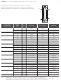
In Tab. 1 auf Seite 4 ist die richtige Pin-Belegung des D-
SUB-Anschlusses für das VS LS04 mit der
Anschlussvariante 1 dargestellt.
lguun Vorkonfektionierte Kabel mit passendem D-SUB-
Gegenstecker finden Sie im Online-Katalog unter
www.aventics.com/pneumatics-catalog.
Benutzen Sie ein Anschlusskabel für 24 V über
Trenntrafo mit Basisisolierung nach EN 20178,
Klassifikation VDE 0160.
1 About this assignment
scheme
This assignment scheme contains important information
on the safe and appropriate establishment of the correct
pin assignment for the D-SUB control of the LS04 valve
terminal system with 12 bistable valve plates.
O Read this assignment scheme thoroughly before
configuring the mating plug of the D-SUB connection.
O Keep this scheme in a location where it is accessible to
all users.
Related documents
W VS LS04 operating instructions
W Technical data and information pursuant to the nline
catalog at www.aventics.com/pneumatics-catalog
2 The following must be
observed
W Use the information in this scheme solely for the pin
assignment of a mating plug for the D-SUB bushing of
the VS LS04 with the cited maximum configuration.
W Observe the information contained in this assignment
scheme as well as all related documents and
accompanying documents.
W Adhere to national accident prevention regulations at
the place of installation.
W Ensure that the pin assignment of the mating plug is
only carried out by qualified and trained specialists.
W Make sure the system is not under pressure or voltage
before starting work on the VS.
3 Description and applications
The VS LS04 has a 25-pin D-SUB connection on the EP end
plate to control the mounted valves.
The pin assignment of this connection is stipulated by the
selected configuration.
To ensure correct valve control, the mating plug has to be
configured in such a way that each pin of the D-SUB
connection is correctly controlled by the controlling
electronics.
The correct pin assignment of the D-SUB connection for
the VS LS04 with connection variant 1 is shown in Tab. 1
on page 4.
Tip: Pre-assembled cables with suitable
D-SUB mating plugs can be found in the online catalog at
www.aventics.com/pneumatics-catalog.
Use a connection cable for 24 V via an isolating
transformer with basic isolation according to EN
20178, classification VDE 0160.
AVENTICS | VS LS04 | R412008226–BAL–001–AC | Deutsch/English
1
Seite wird geladen ...

Ventilplatz /
Valve position /
Emplacement de
distributeur
Spule /
Solenoid /
Bobine
Pin Adernfarbe Wire color Couleur du fil
1 14 1 weiß white blanc
12 2 braun brown brun
2 14 3 grün green vert
12 4 gelb yellow jaune
3 14 5 grau gray gris
12 6 rosa pink rose
4 14 7 blau blue bleu
12 8 rot red rouge
5 14 9 schwarz black noir
12 10 violett violet violet
6 14 11 grau/rosa gray/pink gris/rose
12 12 blau/rot blue/red bleu/rouge
7 14 13 weiß/grün white/green blanc/vert
12 14 braun/grün brown/green brun/vert
8 14 15 weiß/gelb white/yellow blanc/jaune
12 16 gelb/braun yellow/brown jaune/brun
9 14 17 weiß/grau white/gray blanc/gris
12 18 grau/braun gray/brown gris/brun
10 14 19 weiß/rosa white/pink blanc/rose
12 20 rosa/braun pink/brown rose/brun
11 14 21 weiß/blau white/blue blanc/bleu
12 22 braun/blau brown/blue brun/bleu
12 14 23 weiß/rot white/red blanc/rouge
12 24 braun/rot brown/red brun/rouge
0V GND 25 weiß/schwarz white/black blanc/noir
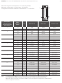
Pin-Belegung für D-SUB-Anschluss am VS LS04 mit 12 Ventilplätzen für Maximalkonfiguration
Pin assignment for D-SUB connection on the VS LS04 with 12 valve positions for max. config
Affectation des broches pour connecteur D-SUB sur le VS LS04 doté de 12 emplacement de distributeurs
pour la configuration maximale
3
Tab. 1
AVENTICS | VS LS04 | R412008226–BAL–001–AC | Deutsch/English/Français
Maximalkonfiguration Ventilplatten: 12 x beidseitig betätigt
Maximum configuration for valve plates: 12x bistable
Configuration maximale embases de distributeurs : 12 x bistables
1
14
13
25
Seite wird geladen ...
Seite wird geladen ...
Seite wird geladen ...
Seite wird geladen ...
-
 1
1
-
 2
2
-
 3
3
-
 4
4
-
 5
5
-
 6
6
-
 7
7
-
 8
8


AVENTICS Series LS04 Assembly Instructions
- Typ
- Assembly Instructions
- Dieses Handbuch eignet sich auch für
in anderen Sprachen
- English: AVENTICS Series LS04
- français: AVENTICS Series LS04
- español: AVENTICS Series LS04
- italiano: AVENTICS Series LS04
- svenska: AVENTICS Series LS04
Verwandte Artikel
-
AVENTICS Series LS04 Assembly Instructions
-
AVENTICS Series CON-MP Assembly Instructions
-
-
-
-