
Güterwagen
Trieb- und Beiwagen • Rail and side car
Mouvement et voiture supplémentaire
Motorový vůz a vagon
Wagon silnikowy i wagon doczepny
www.tillig.com www.facebook.com/tilligbahn 364545 / 14.09.2023
112
Art.-Nr. / Item no. / Réf. / Art.-č. / Nr art.
70004 • 70021 • 70022 • 70032 • 70054 • 74192 • 74193
286
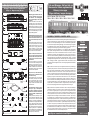
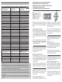
(DE) Das Modell ist eine maßstäbliche Nachbildung des Originals mit authentischer Farb-
gebung und Beschriftung. Der Antrieb erfolgt über einen fünfpoligen Motor auf beide
Achsen. Durch eine Dreipunktauage ist eine sichere Stromaufnahme gewährleistet.
Der Lichtwechsel erfolgt fahrtrichtungsabhängig, eine Innenbeleuchtung ist eingebaut.
Da der Beiwagen nicht die Funktion eines Steuerwagens hat, ist für die Kupplung der
Fahrzeuge eine normale Kupplung ohne Stromübertragung vorgesehen.
Das Modell erreicht nach einer Einlaufzeit von ca. 20 Minuten in beide Fahrtrichtungen
seine optimalen Fahreigenschaften. Ab Werk ist das Modell ausreichend gefettet. Ein
Nachfetten oder -ölen mit harz- und säurefreiem Fett oder Öl ist erst nach ca. 100 Be-
triebsstunden zu empfehlen. Dazu geeignetes Fett ist unter TILLIG Art.-Nr. 08973 er-
hältlich. Zur weiteren Detaillierung des Modells sind Zurüstteile beigelegt. Die über dem
Kupplungs-Normschacht einzusteckenden Bremsschlauchträger können nur bedingt
vollständig am Modell angesteckt werden. Bei Verwendung von Kurzkupplungen können
diese – abhängig vom Radius – gegen die Trittstufen stoßen. Daher müssen sie unter
Umständen entsprechend gekürzt werden, wenn die Kupplungsdeichsel ausschwenken
können muss.
(GB) The model is a true scale replica of the original with authentic livery and markings. It
is powered by a ve pole motor on both axles. A three-point support ensures secure current
draw. Light change is switched depending on direction. Interior lighting is installed. As the
sidecar does not function as a control car, the car has a normal coupler without current
transfer. The model achieves its optimum driving characteristics after a running-in time of
approx. 20 minutes in both directions. The model comes suciently greased at delivery.
Regreasing or oiling with acid-free and resin-free lubricant or oil is only necessary after
approx. 100 operating hours. Suitable grease is TILLIG with the Item no. 08973. Acces-
sories are included for further detailing the model. Brake hose carriers to be inserted over
the coupling standard duct can only be partially added on the model. When using close
couplers, these can – dependent on the radius – hit against the steps. Therefore, they may
need to be correspondingly shortened if the coupling drawbar needs to swing out.
(FR) Le modèle est une reproduction à l’échelle avec couleur et inscription authentiques.
L’entraînement s’eectue par un moteur à 5 pôles sur les deux essieux. Une absorption
de courant sûre est garantie grâce à un support trois points. Le changement de lumière
s’eectue en fonction du sens de la marche, un éclairage intérieur est intégré. Comme la
voiture supplémentaire n’a pas la fonction d’une voiture de commande, il est prévu pour
l’attelage des voitures un attelage normal sans transmission de courant. Après une péri-
ode de rodage d’env. 20 minutes dans les deux sens de marche, le modèle atteint ses
caractéristiques optimales de marche. Le modèle est susamment graissé à l’usine. Nous
recommandons de regraisser ou rehuiler avec une graisse ou une huile exempte de résine
et d’acide après env. 100 heures de service. La graisse adaptée est disponible chez Tillig,
réf.: 08973. Pour apporter plus de détails au modèle, quelques accessoires sont joints.
Les supports de tuyau de frein à insérer par la chambre à câbles normalisés ne peuvent
être entièrement branchés au modèle que sous conditions. Lors de l’utilisation d’attelages
courts, ceux-ci peuvent heurter les marches – selon le rayon. C’est pourquoi, ils doivent
être éventuellement raccourcis si la barre d’attelage doit pivoter.
-
-
Dieses Produkt darf am Ende seiner Nut-
zungsdauer nicht über den normalen Haus-
müll entsorgt werden, sondern muss an einem
Sammelpunkt für das Recycling von elektri-
schen und elektronischen Geräten abgegeben
werden. Bitte fragen Sie bei Ihrem Händler
oder der Gemeindeverwaltung nach der zu-
ständigen Entsorgungsstelle.
When this product comes to the end of its use-
ful life, you may not dispose of it in the ordinary
domestic waste but must take it to your local
collection point for recycling electrical and
electronic equipment. If you don’t know the
location of your nearest disposal centre please
ask your retailer or the local council oce.
À la n de sa durée de vie, ne pas éliminer
ce produit avec les déchets ménagers mais le
remettre à un point de collecte pour le recy-
clage d’appareils électriques et électroniques.
Veuillez vous adresser à votre revendeur ou à
l’administration communale pour connaître les
points d’élimination compétents.
Tento produkt nesmí být na konci svého uží-
vání zlikvidován jako běžný domovní odpad,
ale musí být zlikvidován např. ve sběrném
dvoře. Prosím, zeptejte se vašeho obchodní-
ka, popř. na svém obecním úřadě o vhodném
způsobu likvidace.
-
Produkty oznaczone przekreślonym pojem-
nikiem po zakończeniu użytkowania nie mogą
być usuwane razem z normalnymi odpadami
domowymi, lecz muszą być przekazywane do
punktu zbierania i recyklingu urządzeń elektry-
cznych i elektronicznych. Dzięki recyklingowi
pomagają Państwo skutecznie chronić środo-
wisko naturalne. Prosimy zwrócić się do spec-
jalistycznego sklepu lub do odpowiedniego
urzędu w Państwa okolicy, aby dowiedzieć się,
gdzie jest najbliższy punkt recyklingu urząd-
zeń elektrycznych i elektronicznych.
Promenade 1
01855 Sebnitz
Tel.: +49 (0)35971 / 903-45
Fax: +49 (0)35971 / 903-19
(DE) Hotline Kundendienst
(GB) Hotline customer service
(FR) Services à la clientèle Hotline
(CZ) Hotline Zákaznické služby
(PL) Biuro Obsługi Klienta:
www.tillig.com/
Service_Hotline.html
(DE) Technische Änderungen
vorbehalten!
Bei Reklamationen wenden Sie
sich bitte an Ihren Fachhändler.
(GB) Subject to technical
changes! Please contact your
dealer if you have any comp-
laints.
(FR) Sous réserve de
modications techniques!
Pour toute réclamation, adres-
sez-vous à votre revendeur.
(CZ) Technické změny vyhra-
zeny! Při reklamaci se obraťte
na svého obchodníka.
(PL) Zastrzega się możliwość
zmian technicznych!
W przypadku reklamacji
prosimy zgłaszać się do
specjalistycznego sprzedawcy.
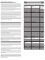
Lfd. Nr. Bezeichnung Art.-Nr.
1a
1b
2
3
4
5a
5b
6
7
8
9
10
11
12
13
14
15
16
17
18
19
20
21
22
23
24
25
26
27
28
o.Abb.
o.Abb.
Oberteil, vollst. (74192)
Oberteil, vollst. (74191)
Oberteil, vollst. (74193)
Oberteil, vollst. (70004)
Puffer, flach
Puffer, ballig
Leiterplatte (Dach)
Inneneinrichtung, o. Abb. (74192)
Inneneinrichtung (74191/74193)
Leiterplatte, vollst.
Bremsbacken
Achslager li.
Achslager re.
Träger
Trittstufe li.
Trittstufe re.
Rahmen, lack.
Kinematik
Bremsschlauchträger
Standartkupplung
Zugfeder 0,18x2,5x5,64
Radsatz
Abortrohr
Batteriekasten
Hauptluftbehälter
Hilfsluftbehälter
Bremszylinder
Dofa Ofen
Kohlebehälter
Leitung 1
Leitung 2
Leitung 3
Radschleifer
Zurüstteile (74191/70004)
Zurüstteile (74192)
Zurüstteile (74193)
203005
203028
203073
203428
341050
341060
396403
207341
207342
203004
309099
309089
309090
309093
309091
309092
207273
309139
307470
293700
395420
210906
309106
309105
309098
309104
309103
309101
309100
309095
309096
309097
396232
203031
203008
203075
Achtung!
Die Lok-Betriebsnummern der Artikel wechseln
unter Umständen bei Neuproduktion. Ersatzteile
zu den Art.-Nr. tragen die jeweils in der Produktion
befindlichen Betriebsnummern. Ersatzteile mit
älteren Betriebsnummern nur solange Vorrat reicht.
364545-S.4
04.06.2013
13
11
15
19
7
11
16
12
5b
7
2
3
4
8
14
22
20
21
9
3
2
1a
15
23
18
ERSATZTEILLISTE
Beiwagen
VB 140
Nicht geeignet für Kinder unter 3 Jahren
wegen abnehmbarer und verschluckbarer
Kleinteile und Verletzungsgefahr durch
funktionsbedingte scharfe Ecken und Kanten.
0-3
Dieses Produkt darf am Ende seiner Nutzungsdauer
nicht über den normalen Hausmüll entsorgt werden, sondern
muss an einem Sammelpunkt für das Recycling von elektrischen
und elektronischen Geräten abgegeben werden.iiiiiiiiiiiiiiiiiiiiiiiiii
Bitte fragen Sie bei Ihrem Händler oder der Gemeindeverwaltung
nach der zuständigen Entsorgungsstelle.
Technische Änderungen vorbehalten!
Bei Reklamationen
diese Anleitung bitte über Ihren Fachhändler
mitsenden an:
TILLIG Modellbahnen GmbH
Promenade 1, 01855 Sebnitz
Tel. +49 (0)35971 903-45
Fax +49 (0)35971 903-19
Service-Hotline:
unsere aktuellen Hotline-Zeiten finden Sie unter:
www.tillig.com
12
17 17
18
24
25
26
27
28
143
1b
2
3
3
2
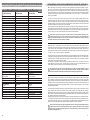
3
2
1a
2
3
3
2
1b
2
3
4
5
6
77
89
11 10
12
15 15
10 11
13
14
14
16
16
17
17
18 23
19
20
24
21
25
26
22
27
Beiwagen • Sidecar • Voiture supplémentaire
Vlečný vůz • Wagon doczepny VB 140

Model je napodobenina originálu v přesném měřítku včetně autentického zbarvení a popisů. Pohon zajišťuje pětipólový motor
na obě nápravy. Tříbodová struktura zajišťuje spolehlivý odběr proudu. Přepínání světel probíhá podle směru jízdy, zabudované je
vnitřní osvětlení. Vagon nemá funkci motorového vozu, proto jsou spřáhla obou vozů běžná spřáhla bez přenosu elektrického pro-
udu. Po záběhu trvajícím zhruba 20 minut v obou směrech dosáhne model svých optimálních jízdních vlastností. Z výroby je model
již dostatečně namazán. Domazání nebo olejování mazacím tukem nebo olejem bez obsahu pryskyřic a kyselin se doporučuje
teprve po cca 100 provozních hodinách. K tomu účelu je vhodný mazací tuk TILLIG Art.-č. 08973.
Pro další detailní vybavení modelu jsou přiloženy některé díly příslušenství. Držáky brzdových hadic, které lze nasadit nad normo-
vaným držákem spřáhla, lze na model nasadit pouze omezeně. Krátká spřáhla mohou při použití podle poloměru kolejí případně
kolidovat se schůdky. Proto je zkraťte podle potřeby, pokud se oj spřáhla musí naklápět.
(PL) Model to odpowiednia do skali kopia oryginału o autentycznej kolorystyce i z autentycznymi opisami. Model jest napędzany
pięciobiegunowym silnikiem na obu osiach. Podparcie w trzech punktach zapewnia bezpieczny pobór prądu. Oświetlenie zmienia
się zależnie od kierunku jazdy, zamontowane jest też oświetlenie wnętrza. Ponieważ wagon doczepny nie pełni funkcji wagonu
sterowniczego, to dla sprzęgania pojazdów przewidziano sprzęg zwyczajny, bez przeniesienia prądu. Model po ok. 20 minutach
docierania osiąga optymalne właściwości jezdne w obu kierunkach jazdy. Model został dostatecznie nasmarowany przez pro-
ducenta. Powtórne smarowanie lub oliwienie za pomocą wolnego od żywic i kwasów smaru lub oleju zaleca się dopiero po ok. 100
godzinach eksploatacji. Odpowiedni do tego celu smar dostępny jest pod Nr. art. TILLIG 08973.
Dla wyposażenia modelu w kolejne detale dołączono kilka dodatkowych akcesoriów. Wsporniki węży gumowych sprzęgu hamul-
cowego zakładane poprzez kasetę normowaną sprzęgu można tylko warunkowo całkowicie montować na modelu. W przypadku
stosowania sprzęgów krótkich mogą one – zależnie od promienia – uderzać o schodki. Dlatego w razie konieczności należy je
odpowiednio skrócić, jeżeli konieczne jest wychylanie dyszla sprzęgu.
11
• •• •
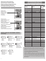
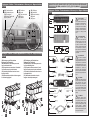
(DE) Das Modell ist für den Einbau eines Decoders vorgesehen. Dazu verfügt das Modell über eine Schnittstelle nach NEM 651.
Der Steckplatz bendet sich beim Triebwagen auf der Platine unter der Inneneinrichtung im Bereich der Toilette. Beim Beiwagen
bendet sich der Steckplatz unter der Inneneinrichtung. Ein Lötpad (Kennzeichnung F1) zur getrennten Ansteuerung der Innen-
beleuchtung mit einem Decoder, der separat per Kabel herausgeführte Funktionen besitzt, ist neben dem Steckplatz auf der
Leiterplatte angebracht. Das Bauteil zwischen den Anschlüssen JMP 1.1 und JMP 1.2 ist zu entfernen. (siehe Abb. Seite 4) Beide
Fahrzeuge benötigen einen eigenen Decoder.
Zum Önen des Triebwagens zunächst die beiden Bremsschlauchträger aus den Kupplungsaufnahmen heraus ziehen. Anschlie-
ßend die stirnseitigen Rastnasen lösen. Sie liegen in der Mitte (Bestandteil des Frontfensters). Die Rastnasen müssen mit einem
Schraubendreher nach außen gedrückt werden. Dann kann das Gehäuse nach oben abgenommen werden. Beim Zusammenbau
zunächst die Inneneinrichtung und die Dachleiterplatte auf das Unterteil legen. Nach dem Einhängen von Schaltkasten und Kühl-
schlangen kann das Gehäuse wieder aufgerastet werden.
Das Oberteil des Beiwagens ist mit zwei seitlichen Rasten je Wagenseite auf das Fahrgestell gerastet. Nach dem Spreizen des
Oberteils kann dieses abgenommen werden. Danach kann die Inneneinrichtung abgenommen werden. Sie rastet vorn und hinten
im Mittelgang auf der Deichselabdeckung. Beim Aufsetzen achten Sie bitte auf die Kodierung der Inneneinrichtung zum Wagen-
boden hin. Entsprechend der Lage des Toilettenfensters ist das Oberteil aufzusetzen.
(GB) The model is designed to accommo-date a decoder. For this purpose the model is equipped with a NEM 651 connector. The
slot is located on the circuit board on the railcar under the interior near the toilet. The slot on the sidecar is under the interior. A
solder pad (designation F1) to the separated actuator of the interior lighting with a decoder which carries out the functions separa-
tely via cable is tted to the circuit board next to the slot. The component between the connections JMP 1.1 and JMP 1.2 is to be
removed. (see Fig. page 4) Both vehicles required their own decoder.
To open the railcar rst remove the two brake hose carriers from the coupler pockets. Then loosen the facing side lugs. They are
located in the middle (part of the front window). The lugs must be pressed outwards with a screwdriver. The housing can then be
removed. When assembling rst place the interior and the roof circuit board on the base. Once the switch box and cooling coils
have been added the housing can be clicked back into place.
The top of the sidecar clicks into the running gear by means of lugs, two on each side. The top section is widened and then
removed. Then the interior can be removed. It clicks in place at the front and rear in the centre section on the drawbar cover.
When tting please pay attention to the coding of the interior to the car oor. The top section is placed on top corresponding to
the position of the toilet window.
!
2
!
Część górna, kompletny (70004)
Część górna, kompletny (70021)
Część górna, kompletny (70022)
Część górna, kompletny (70032)
Część górna, kompletny (70054)
Część górna, kompletny (74192)
Część górna, kompletny (74193)
Zderzak, płaski
Zderzak, baryłkowaty
Płytka drukowana, (Dachu)
Wystrój wewnętrzny (70004)
Wystrój wewnętrzny (70021/70022)
Wystrój wewnętrzny (74192/70032)
Wystrój wewnętrzny (70054)
Wystrój wewnętrzny (74193)
Płytka drukowana, kompletny
Szczęki hamulcowe
Łożysko osi, lewo
Łożysko osi, prawo
Schodek, lewo
Schodek, prawo
Ostoja, lak.
Kinematyka
Wspornik węży gumowych sprzęgu hamulcowego
Sprzęg standardowy
Sprężyna cięgła 0,18x2,5x5,64
Zestaw kołowy
Rura ustępu
Skrzynia akumulatorowa
Główny zbiornik powietrza
Zbiornik powietrza pomocniczy
Cylinder hamulcowy
Dofa Ofen
Zbiornik na węgiel
Przewód 1
Przewód 2
Przewód 3
Przewoźnik
Ślizgacz kołowy
Części dodatkowe (70004/70054)
Części dodatkowe (70032/74192)
Części dodatkowe (74193)
Części dodatkowe (70021)
Części dodatkowe (70022)
2
3
5
6
7
8
9
22
23
25
26
27
Svršek, kompletní (70004)
Svršek, kompletní (70021)
Svršek, kompletní (70022)
Svršek, kompletní (70032)
Svršek, kompletní (70054)
Svršek, kompletní (74192)
Svršek, kompletní (74193)
Nárazník, plochý
Nárazník, vypouklý
Deska s plošnými spoji (Střešní)
Vnitřní vybavení (70004)
Vnitřní vybavení (70021/70022)
Vnitřní vybavení (74192/70032)
Vnitřní vybavení (70054)
Vnitřní vybavení (74193)
Deska s plošnými spoji, kompletní
Brzdové čelisti
Ložisko nápravy, levý
Ložisko nápravy, pravý
Stupeň, levý
Stupeň, pravý
Rám, lak.
Kinematika
Nosník brzdových hadic
Standardní spřáhlo
Tažná pružina 0,18x2,5x5,64
Sada kol
Odpadní trubka
Bateriová skříň
Hlavní zásobník vzduchu
Zásobník pomocného vzduchu
Brzdový válec
Dofa Ofen
Zásobník na uhlí
Vedení 1
Vedení 2
Vedení 3
Nosník
Kontakty kol
Příslušenství (70004/70054)
Příslušenství (70032/74192)
Příslušenství (74193)
Příslušenství (70021)
Příslušenství (70022)
Beiwagen • Sidecar • Voiture supplémentaire • Vlečný vůz • Wagon doczepny
VB 140
396232

(FR) Le modèle est prévu pour le montage d’un décodeur. A cet eet, le modèle dispose d’une interface selon NEM 651. Le connec-
teur se trouve à la voiture motrice sur la platine sous l’aménagement intérieur dans la zone des toilettes. Sur la voiture supplémen-
taire, le connecteur se trouve sous l’aménagement intérieur. A côté du connecteur sur la carte de circuits imprimés se trouve un
plot de soudure (identié F1) pour commande séparée de l’éclairage intérieur avec un décodeur qui possède des fonctions guidées
séparément par câble. Retirer le composant entre les raccordements JMP 1.1 et JMP 1.2. (voir illustr. p. 4). Les deux voitures ont
besoin d’un propre décodeur.
Pour ouvrir la voiture motrice, enlever d’abord les deux supports de tuyau de frein des logement d’attelage. Ensuite, desserrer
les taquets de blocage côté frontal. Ils se trouvent au milieu (élément de la fenêtre frontale). Les taquets de blocage doivent être
pressés vers l’extérieur avec un tournevis. Ensuite, le boîtier peut être retiré vers le haut. Lors de l’assemblage, poser d’abord
l’aménagement intérieur et la carte de circuits imprimés sur la partie inférieure. Après suspension du coret de commande et des
serpentins de refroidissement, le boîtier peut être à nouveau assemblé.
La partie supérieure de la voiture supplémentaire doit être enclenchée sur le châssis par deux taquets latéraux par côté de voiture.
Après écartement de la partie supérieure, celle-ci peut être retirée. Ensuite, l’aménagement intérieur peut être retiré. Il s’encliquette
devant et derrière au milieu sur le recouvrement de la barre d’attelage. Lors de la pose, veiller au codage de l’aménagement intéri-
eur vers le sol de la voiture. Placer la partie supérieure selon la position de la fenêtre des toilettes.
-
Model je určen pro montáž dekodéru. K tomu účelu je model vybaven rozhraním dle NEM 651. Místo nasazení se nachází
na motorovém voze na desce plošných spojů pod vnitřním vybavením v oblasti toalety. U vagonu se místo nasazení nachází pod
vnitřním vybavením. Pájecí plocha (označená F1) pro oddělené ovládání vnitřního osvětlení pomocí dekodéru, jehož funkce jsou
vyvedeny samostatnými kabely, se nachází vedle zásuvného místa na desce plošných spojů. Odstraňte díl mezi přípojkami JMP
1.1 a JMP 1.2. (viz obr. S.4). Oba vozy potřebují svůj vlastní dekodér.
Pro otevření motorového vozu nejdříve vytáhněte oba držáky brzdových hadic z držáků spřáhel. Poté uvolněte čelní aretační západ-
ky. Nacházejí se uprostřed (součást čelního okna). Aretační západky zatlačte šroubovákem směrem ven. Poté můžete pouzdro
sundat směrem nahoru. Při montáži nejdříve vložte vnitřní vybavení a střešní desku plošných spojů na dolní část. Po zavěšení
ovládací skříně a chladicí spirály lze pouzdro opět nasadit.
Horní část vagonu je připevněna k podvozku dvěma bočními západkami na každé straně vozu. Po rozevření horní části ji lze
sundat. Následně lze vyjmout vnitřní vybavení. Je zajištěna vpředu a vzadu uličky ke krytu oje. Při nasazování dávejte pozor na
kódování vnitřního vybavení vůči podlaze vozu. Horní část nasaďte podle polohy okna toalety.
(PL) Na modelu prze-widziano montaż dekodera. W tym celu model dysponuje złączem zgodnym z NEM 651. W przypadku
wagonu silnikowego slot znajduje się na płytce drukowanej pod wyposażeniem wewnętrznym w rejonie toalety. W przypadku
wagonu doczepnego slot znajduje się pod wyposażeniem wewnętrznym. Pad lutowniczy (oznaczenie F1) do osobnego sterowania
oświetleniem wnętrza za pomocą dekodera pełniącego funkcje wyprowadzane osobno przez kabel, znajduje się obok slotu na
płytce drukowanej. Część znajdującą się pomiędzy przyłączami JMP 1.1 oraz JMP 1.2 należy usunąć (patrz rys. s.4). Oba pojazdy
wymagają własnych dekoderów.
W celu otwarcia wagonu silnikowego należy wpierw wyciągnąć oba wsporniki węży gumowych sprzęgu hamulcowego z uchwytów
sprzęgu. Następnie należy odczepić noski zatrzasków po stronie czołowej. Znajdują się one w środku (część okna przedniego).
Noski zatrzasków należy wypchnąć na zewnątrz przy pomocy śrubokręta. Następnie można zdjąć obudowę. W przypadku montażu
najpierw założyć na część dolną wyposażenie wnętrza oraz płytkę drukowaną dachową. Po zawieszeniu skrzynek rozdzielczych i
węży chłodzących można założyć i zatrzasnąć obudowę.
Część górna wagonu doczepnego umocowana jest do podwozia za pomocą dwóch zatrzasków bocznych po każdej stronie wago-
nu. Część górną można zdjąć po rozszerzeniu jej na boki. Następnie można wyjąć wyposażenie wnętrza. Wyposażenie zamocowa-
ne jest za pomocą zatrzasków z przodu i z tyłu w przejściu środkowym. Przy nakładaniu należy uważać na kodowanie wyposażenia
wnętrza w stosunku do podłogi wagonu. Część górną należy założyć odpowiednio do położenia okna toalety.
• •• •
!
!
!
310
Oberteil, vollst. (70004)
Oberteil, vollst. (70021)
Oberteil, vollst. (70022)
Oberteil, vollst. (70032)
Oberteil, vollst. (70054)
Oberteil, vollst. (74192)
Oberteil, vollst. (74193)
Puer, ach
Puer, ballig
Leiterplatte (Dach)
Inneneinrichtung (70004)
Inneneinrichtung (70021/70022)
Inneneinrichtung (74192/70032)
Inneneinrichtung (70054)
Inneneinrichtung (74193)
Le iterpla tt e, vollst.
Bremsbacken
Achslager links
Achslager rechts
Tr itts t ufe, l i nks
Tri tts tufe, rec hts
Rahmen, lack.
Kinematik
Bremsschlauchträger
St an da rtkupplung
Z u g f e d e r 0, 18 x 2, 5 x5 ,6 4
Radsatz
Abortrohr
Batteriekasten
Hauptluftbehälter
Hilfsluftbehälter
Bremszylinder
Dofa Ofen
Kohlebehälter
Leitung 1
Leitung 2
Leitung 3
Träger
Radschleifer
Zurüstteile (70004/70054)
Zurüstteile (70032/74192)
Zurüstteile (74193)
Zurüstteile (70021)
Zurüstteile (70022)
Top part, complete (70004)
Top part, complete (70021)
Top part, complete (70022)
Top part, complete (70032)
Top part, complete (70054)
Top part, complete (74192)
Top part, complete (74193)
Buer, at
Buer, spherical
Circuit board (Roof)
Interior equipment (70004)
Interior equipment (70021/70022)
Interior equipment (74192/70032)
Interior equipment (70054)
Interior equipment (74193)
Circuit board, complete
Brake shoe
Axle bearing, left
Axle bearing, right
Step, left
Step, right
Frame, varnish.
Kinematics
Brake hose carrier
Standard coupling
Tension spring 0,18x2,5x5,64
Wheel set
Toilet pipe
Battery box
Main air tank
Auxiliary air container
Brake cylinder
Dofa Ofen
Coal container
Line 1
Line 2
Line 3
Beam
Wheel contact
Accessory parts (70004/70054)
Accessory parts (70032/74192)
Accessory parts (74193)
Accessory parts (70021)
Accessory parts (70022)
Partie supérieure, complète (70004)
Partie supérieure, complète (70021)
Partie supérieure, complète (70022)
Partie supérieure, complète (70032)
Partie supérieure, complète (70054)
Partie supérieure, complète (74192)
Partie supérieure, complète (74193)
Tampon, plat
Tampon, en forme de balle
Carte de circuits imprimés (Toit)
Dispositif intérieur (70004)
Dispositif intérieur (70021/70022)
Dispositif intérieur (74192/70032)
Dispositif intérieur (70054)
Dispositif intérieur (74193)
Carte de circuits imprimés, complète
Segment de frein
Coussinet d’essieu, gauche
Coussinet d’essieu, droite
Marche, gauche
Marche, droite
Châssis, laqué
Cinématique
Support de tuyau de frein
Attelage standard
Ressort de traction 0,18x2,5x5,64
Essieux montés
Evacuation toilettes
Boîte de batterie
Réservoir d’air principal
Réservoir d’air d’appoint
Cylindre de frein
Dofa Ofen
Conteneur à charbon
Conduite 1
Conduite 2
Conduite 3
Faisceau
Capteur de roue
Pièces d’équipement (70004/70054)
Pièces d’équipement (70032/74192)
Pièces d’équipement (74193)
Pièces d’équipement (70021)
Pièces d’équipement (70022)
2
3
5
6
7
8
9
22
23
25
26
27
Beiwagen • Sidecar • Voiture supplémentaire • Vlečný vůz • Wagon doczepny
VB 140

94
(DE) Anschlussplan für schaltbare Innenbeleuchtung
(GB) Connection diagram for switchable interior lighting
(FR) Plan de raccordement pour l’éclairage intérieur commutable
(CZ) Schéma zapojení zapínatelného vnitřního osvětlení
(PL) Plan podłączenia dla przełączalnego oświetlenia wnętrza
(DE) Bauteil entfernen
(GB) Remove component
(FR) Enlever le composant
(CZ) Odstraňte díl
(PL) Usunąć część
(DE) Decoder-Anschluss:
schaltbare Innenbeleuchtung Lötpad F1
(GB) Decoder connection:
Switchable interior lighting solder pad F1
(FR) Raccordement de décodeur:
éclairage intérieur commutable plot de soudure F1
(CZ) Připojení dekodéru:
připojitelné vnitřní osvětlení k pájecí ploše F1
(PL) Przyłącze dekodera:
przełączalne oświetlenie wnętrza pad lutowniczy F1
• ••
A(DE) Gristange
(GB) Handle bar
(FR) Barre de maintien
Madlo
(PL) Poręcz
B(DE) Gristange, 9 mm
(GB) Handle bar, 9 mm
(FR) Barre de maintien, 9 mm
Madlo, 9 mm
(PL) Poręcz, 9 mm
C(DE) Gristange; 2,3 mm
(GB) Handle bar; 2,3 mm
(FR) Barre de maintien; 2,3 mm
Madlo; 2,3 mm
(PL) Poręcz; 2,3 mm
D(DE) Gristange; 1,8 mm
(GB) Handle bar; 1,8 mm
(FR) Barre de maintien; 1,8 mm
Madlo; 1,8 mm
(PL) Poręcz; 1,8 mm
E(DE) Kuppelhaken
(GB) Coupling
(FR) Crochet d’attelage hook
Hák spřáhla
(PL) Hak cięgłowy
F(DE) Bremsschläuche
(GB) Brake hoses
(FR) Tuyaux de frein
Vzduchové hadice
(PL) Przewody hamulcowe
G(DE) Scheibenwischer
(GB) Windshield wipers
(FR) Essuie-glace
Stěrače čelního skla
(PL) Wycieraczki
H(DE) Steckdosen
(GB) Sockets
(FR) Prises de courant
Zásuvky
(PL) Gniazda
Część górna, kompletny (70004)
Część górna, kompletny (70021)
Część górna, kompletny (70022)
Część górna, kompletny (70032)
Część górna, kompletny (70054)
Część górna, kompletny (74192)
Część górna, kompletny (74193)
Zderzak, płaski
Zderzak, baryłkowaty
Płytka drukowana, (Dachu)
Wystrój wewnętrzny
Płytka drukowana, kompletny
Mechanizm wahliwy, kompletny
Wał kardana
Silnik, kompletny
Przekładnia stała
Szczęki hamulcowe, lewo
Szczęki hamulcowe, prawo
Łożysko osi, przód/lewo
Łożysko osi, przód/prawo
Łożysko osi, tył/lewo
Łożysko osi, tył/prawo
Schodek, lewo
Schodek, prawo
Wężownica chłodząca
Skrzynka rozdzielcza
Ostoja, lak.
Kinematyka
Wspornik węży gumowych sprzęgu hamulcowego
Kocioł podwójny
Sprzęg standardowy
Sprężyna cięgła 0,18x2,5x5,64
Śruba z łbem PT M 1,8x4,3
Śruba z łbem KN 5041 M 1,8x4,8
Płytka przeciwzakłóceniowa
Ślizgacz kołowy
Części dodatkowe (70004/70022/70054)
Części dodatkowe (70032/74192)
Części dodatkowe (74193)
Części dodatkowe (70021)
2
3
5
6
7
8
9
22
23
25
26
396232
Svršek, kompletní (70004)
Svršek, kompletní (70021)
Svršek, kompletní (70022)
Svršek, kompletní (70032)
Svršek, kompletní (70054)
Svršek, kompletní (74192)
Svršek, kompletní (74193)
Nárazník, plochý
Nárazník, vypouklý
Deska s plošnými spoji (Střešní)
Vnitřní vybavení
Deska s plošnými spoji, kompletní
Otoč, kompletní
Kardan
Motor, kompletní
Pevný převod
Brzdové čelisti, levý
Brzdové čelisti, pravý
Ložisko nápravy, přední/ levý
Ložisko nápravy, přední/pravý
Ložisko nápravy, zadní/ levý
Ložisko nápravy, zadní/pravý
Stupeň, levý
Stupeň, pravý
Chladicí spirála
Rozvaděč
Rám, lak.
Kinematika
Nosník brzdových hadic
Dvojitý kotel
Standardní spřáhlo
Tažná pružina 0,18x2,5x5,64
Zápustný šroub PT M 1,8x4,3
Zápustný šroub KN 5041 M 1,8x4,8
Deska tištěného spoje
Kontakty kol
Příslušenství (70004/70022/70054)
Příslušenství (70032/74192)
Příslušenství (74193)
Příslušenství (70021)
Triebwagen • Railcar • Train automoteur • Motorový vůz • Wagon silnikowy
VT 135
Pour les véhicules à interface intégrée, les droits de garantie ne peuvent être acceptés que si le véhicule correspondant
est restitué au revendeur dans l’état de livraison (sans décodeur numérique intégré, avec l’antiparasite installé).
Pro tento výrobek TILLIG platí zákonný záruční nárok 21 měsíců od data koupě. Tento záruční nárok
zaniká, pokud byly ze strany zákazníka na výrobku provedeny zásahy, změny, přestavby atd. U vozidel se zabudovaným
rozhraním mohou být záruky uplatněny jen tehdy, když bude předmětné vozidlo vráceno do odborné prodejny v původním
stavu (bez zabudovaného digitálního dekodéru, se zasunutou odrušovací sadou).
(PL) dla niniejszego produktu TILLIG obowiązuje ustawowe roszczenie gwarancyjne,
wynoszące 24 miesiące od daty zakupu. Roszczenie gwarancyjne wygasa w sytuacji, gdy przeprowadzone zostaną w
produkcie zmiany lub klient dokona przebudowy produktu na własną rękę. W pojazdach z zabudowanym interfejsem,
roszczenia gwarancyjne mogą być podnoszone jedynie, gdy dany pojazd przekazany zostanie przedstawicielowi hand-
lowemu w stanie, jaki obowiązywał w momencie dostawy (bez zabudowanego dekodera cyfrowego, z osadzonym
zestawem odkłócającym).

58
(DE) Gristangen sauber von den Spritzlingen entfernen.
(GB) Remove the grip rail cleanly from the sprues.
(FR) Bien enlever les barres de maintien des pièces moulées.
(CZ) Zábradlí čistě oddělte od výlisku.
(PL) Oddzielić czysto poręcze z wypraski wtryskowej.
(DE) Gristange A, B, C, D
(GB) Handle bar A, B, C, D
(FR) Barre de maintien A, B, C, D
Madlo A, B, C, D
(PL) Poręcz A, B, C, D
(DE) Nach dem Vereinzeln werden die Gristan-
gen gemäß den Skizzen (siehe Abb. Seite 6) in den
Bohrungen mit je einem Tropfen Sekundenkleber
xiert.
Nach den vorhandenen Abbildungen hat es bei
diesen Triebwagen anfangs eine hängende, spä-
ter eine stehende Anordnung der Scheibenwischer
am mittleren Stirnfenster gegeben. Wir überlassen
es dem Modelleisenbahner, welche Anordnung er
wählt.
Bitte am unteren Rand des mittleren Stirnfensters
ein Loch mit Durchmesser 0,9 mm bohren, den
Scheibenwischer einstecken und vorsichtig mit ei-
nem Tropfen Kleber xieren.
(GB) After separation the hand rails are xed in
place in the holes using a drop of superglue accor-
ding to the accompanying sketches.
(see Fig. page 6)
Contemporary pictures show that the early railcars
had a suspended windscreen wiper system and the
later ones a standing arrangement. We leave it up
to the model railway enthusiast to choose the arran-
gement he prefers.
Please drill a 0.9 mm hole on the bottom edge of the
central front window, insert the windscreen wiper
and carefully x in place with a drop of superglue.
(FR) Après les avoir enlevées, xer les barres de
maintien conformément aux schémas ci-contre
dans les trous avec une goutte de colle rapide.
(voir illustr. p. 6)
Selon les illustrations disponibles, au début, les
essuie-glace de ces voitures motrices étaient
suspendues puis ensuite droites à la fenêtre cent-
rale. Nous laissons à l’amateur de train miniature la
disposition qu’il préfère.
Percer au bord inférieur de la fenêtre de visualisa-
tion centrale un trou d’un diamètre de 0,9 mm, in-
troduire l’essuie-glace et xer avec précaution avec
une goutte de colle.
Po očištění zábradlí zajistěte v otvorech podle
vyobrazení vedle kapkou vteřinového lepidla.
(viz obr. S.6)
Podle dostupných vyobrazení se u těchto motoro-
vých vozů nejdříve používaly zavěšené a později
stojaté stěrače na středním čelním okně. Volbu
umístění přenecháváme modeláři.
Na dolním okraji čelního okna vyvrtejte otvor o
průměru 0,9 mm, do kterého nasaďte stěrač a opa-
trně jej zajistěte kapkou lepidla.
(PL) Po oddzieleniu poręcze mocuje się w otworach
za pomocą kropli kleju błyskawicznego zgodnie z
rysunkiem obok. (patrz rys. s.6)
Zgodnie z dostępnymi ilustracjami w przypadku
tego wagonu doczepnego wycieraczki ustawione
były na środkowym oknie czołowym najpierw w
układzie wiszącym, później zaś stojącym. Wybór
ustawienia pozostawiamy budowniczemu kolejki.
Na dolnej krawędzi środkowego okna czołowe-
go należy wywiercić otworek o przekroju 0,9 mm,
założyć tam wycieraczkę i zamocować ją za po-
mocą kropli kleju.
Oberteil, vollst. (70004)
Oberteil, vollst. (70021)
Oberteil, vollst. (70022)
Oberteil, vollst. (70032)
Oberteil, vollst. (70054)
Oberteil, vollst. (74192)
Oberteil, vollst. (74193)
Puer, ach
Puer, ballig
Leiterplatte (Dach)
Innenei nrichtung
Le iterpla tt e, vollst.
S c h w e n kget r i e b e , voll s t .
Kardanwelle
Motor, vollst.
Fes tge trie be, vol l st.
Bremsba c k e n , l i n ks
B r e m sba c k e n, r e c h t s
Achsl a g e r vorn / l i n ks
A c hs l a ge r v or n / r e c ht s
A c h s l a g e r h i n t e n / l i n k s
A c h s l a g e r h i n t e n / r e c h t s
Tr itts t ufe, l i nks
Tri tts tufe, rec hts
Kühlschlange
Schaltkasten
Rahmen, lack.
Kinematik
Bremsschlauchträger
Doppelkessel
St an da rtkupplung
Z u g f e d e r 0, 18 x 2, 5 x5 ,6 4
S e n k s c h r a u b e P T M 1 , 8 x 4 , 3
Senkschraube KN 5041 M 1,8x4,8
Entstörleiterplatte
Radschleifer
Zurüstteile (70004/70022/70054)
Zurüstteile (70032/74192)
Zurüstteile (74193)
Zurüstteile (70021)
Top part, complete (70004)
Top part, complete (70021)
Top part, complete (70022)
Top part, complete (70032)
Top part, complete (70054)
Top part, complete (74192)
Top part, complete (74193)
Buer, at
Buer, spherical
Circuit board (Roof)
Interior equipment
Circuit board, complete
Swivel gears, complete
Cardan shaft
Motor, complete
Fixed gear, complete
Brake shoe, left
Brake shoe, right
Axle bearing, front/left
Axle bearing, front/right
Axle bearing, rear/left
Axle bearing, rear/right
Step, left
Step, right
Cooling coil
Control box
Frame, varnish.
Kinematics
Brake hose carrier
Double boiler
Standard coupling
Tension spring 0,18x2,5x5,64
Countersunk screw PT M 1,8x4,3
Countersunk screw KN 5041 M 1,8x4,8
Interference suppression circuit board
Wheel contact
Accessory parts (70004/70022/70054)
Accessory parts (70032/74192)
Accessory parts (74193)
Accessory parts (70021)
Partie supérieure, complète (70004)
Partie supérieure, complète (70021)
Partie supérieure, complète (70022)
Partie supérieure, complète (70032)
Partie supérieure, complète (70054)
Partie supérieure, complète (74192)
Partie supérieure, complète (74193)
Tampon, plat
Tampon, en forme de balle
Carte de circuits imprimés (Toit)
Dispositif intérieur
Carte de circuits imprimés, complète
Mécanisme d’orientation, complète
Arbre Cardan
Moteur, complète
Engrenage xe, complète
Segment de frein, gauche
Segment de frein, droite
Coussinet d’essieu, avant/gauche
Coussinet d’essieu, avant/droite
Coussinet d’essieu, arrière/gauche
Coussinet d’essieu, arrière/droite
Marche, gauche
Marche, droite
Serpentin de refroidissement
Coret de commande
Châssis, laqué
Cinématique
Support de tuyau de frein
Double chaudière
Attelage standard
Ressort de traction 0,18x2,5x5,64
Vis à tête conique PT M 1,8x4,3
Vis à tête conique KN 5041 M 1,8x4,8
Circuit imprimée antiparasite
Capteur de roue
Pièces d’équipement (70004/70022/70054)
Pièces d’équipement (70032/74192)
Pièces d’équipement (74193)
Pièces d’équipement (70021)
2
3
5
6
7
8
9
22
23
25
26
Triebwagen • Railcar • Train automoteur • Motorový vůz • Wagon silnikowy
VT 135
(DE) Für dieses TILLIG-Produkt gilt der gesetzliche Gewährleistungsanspruch von 24 Monaten ab
Kaufdatum. Dieser Gewährleistungsanspruch erlischt, wenn kundenseitige Eingrie, Veränderungen, Umbauten usw. an
dem Produkt erfolgen/vorgenommen werden. Bei Fahrzeugen mit eingebauter Schnittstelle, können Gewährleistungs-
ansprüche nur geltend gemacht werden, wenn das betreende Fahrzeug im Lieferzustand (ohne eingebautem Digitalde-
coder, mit eingestecktem Entstörsatz) an den Fachhändler zurück gegeben wird.
This TILLIG product is subject to the statutory warranty entitlement of 24 months from the date of
purchase. This warranty claim expires if the product is interfered with, modied or converted after the point of time of the
customer acquiring ownership. Where vehicles have an integrated interface, claims for warranty can only be asserted if
the vehicle concerned is returned in an as-delivered state (without built-in digital decoder, with plugged-in interference
suppression kit).
Pour ce produit TILLIG, le droit de garantie légal de 24 mois à partir de la date d’achat s’applique. Ce
droit de garantie s’éteint si le client procède/a procédé à des interventions, des modications, des transformations, etc.
sur le produit.

6
Triebwagen • Railcar • Train automoteur • Motorový vůz • Wagon silnikowy
VT 135
Lfd. Nr. Bezeichnung Art.-Nr.
1
2
3
4
5
6
7
8
9
10
11
12
13
14
15
16
17
18
19
20
21
22
23
24
25
26
27
28
29
o.Abb.
o.Abb.
Oberteil, vollst. (74191)
Oberteil, vollst. (74192)
Oberteil, vollst. (74193)
Oberteil, vollst. (70004)
Puffer, flach
Puffer, ballig
Leiterplatte (Dach)
Inneneinrichtung
Leiterplatte, vollst.
Schwenkgetriebe, vollst.
Kardanwelle
Motor, vollst.
Festgetriebe, vollst.
Bremsbacken li.
Bremsbacken re.
Achslager V/li.
Achslager V/re.
Achslager H/li.
Achslager H/re.
Trittstufe li.
Trittstufe re.
Kühlschlange
Schaltkasten
Rahmen, lack.
Kinematik
Bremsschlauchträger
Doppelkessel
Standartkupplung
Zugfeder 0,18x2,5x5,64
Senkschraube (E) PT 1,8x4,3
Senkschraube (E) PT 1,8x8
Entstörleiterplatte
Radschleifer
Zurüstteile (74191/70004)
Zurüstteile (74192)
Zurüstteile (74193)
203027
203001
203072
203427
341050
341060
396403
207339
202999
202971
322670
203033
202972
307400
307410
306380
306390
306400
306410
308374
308375
308380
307450
207272
309139
307470
308378
293700
395420
393420
393210
396130
396402
203029
203007
203074
Achtung!
Die Lok-Betriebsnummern der Artikel wechseln
unter Umständen bei Neuproduktion. Ersatzteile
zu den Art.-Nr. tragen die jeweils in der Produktion
befindlichen Betriebsnummern. Ersatzteile mit
älteren Betriebsnummern nur solange Vorrat reicht.
364545-S.3
04.06.2013
15
18
17
11
23
19
11
13
17
21
2
3
4
20
22
25
26
3
2
12
1
12
18
26
ERSATZTEILLISTE
Triebwagen
VT 135
7
89
10
14
16
25
143
29
28 28
27
27 27
27
5
24
17
20
16
11
23
26
25
18
15
12
8
7
6
5
4
3
2
1
2
3
9
11
13
19
17
21
25
18
14
12
24
26
Lfd. Nr. Bezeichnung Art.-Nr.
1a
1b
2
3
4
5a
5b
6
7
8
9
10
11
12
13
14
15
16
17
18
19
20
21
22
23
24
25
26
27
28
o.Abb.
o.Abb.
Oberteil, vollst. (74192)
Oberteil, vollst. (74191)
Oberteil, vollst. (74193)
Oberteil, vollst. (70004)
Puffer, flach
Puffer, ballig
Leiterplatte (Dach)
Inneneinrichtung, o. Abb.
(74192)
Inneneinrichtung (74191/74193)
Leiterplatte, vollst.
Bremsbacken
Achslager li.
Achslager re.
Träger
Trittstufe li.
Trittstufe re.
Rahmen, lack.
Kinematik
Bremsschlauchträger
Standartkupplung
Zugfeder 0,18x2,5x5,64
Radsatz
Abortrohr
Batteriekasten
Hauptluftbehälter
Hilfsluftbehälter
Bremszylinder
Dofa Ofen
Kohlebehälter
Leitung 1
Leitung 2
Leitung 3
Radschleifer
Zurüstteile (74191/70004)
Zurüstteile (74192)
Zurüstteile (74193)
203005
203028
203073
203428
341050
341060
396403
207341
207342
203004
309099
309089
309090
309093
309091
309092
207273
309139
307470
293700
395420
210906
309106
309105
309098
309104
309103
309101
309100
309095
309096
309097
396232
203031
203008
203075
Achtung!
Die Lok-Betriebsnummern der Artikel wechseln
unter Umständen bei Neuproduktion. Ersatzteile
zu den Art.-Nr. tragen die jeweils in der Produktion
befindlichen Betriebsnummern. Ersatzteile mit
älteren Betriebsnummern nur solange Vorrat reicht.
364545-S.4
04.06.2013
13
11
15
19
7
11
16
12
5b
7
2
3
4
8
14
22
20
21
9
3
2
1a
15
23
18
ERSATZTEILLISTE
Beiwagen
VB 140
Nicht geeignet für Kinder unter 3 Jahren
wegen abnehmbarer und verschluckbarer
Kleinteile und Verletzungsgefahr durch
funktionsbedingte scharfe Ecken und Kanten.
0-3
Dieses Produkt darf am Ende seiner Nutzungsdauer
nicht über den normalen Hausmüll entsorgt werden, sondern
muss an einem Sammelpunkt für das Recycling von elektrischen
und elektronischen Geräten abgegeben werden.iiiiiiiiiiiiiiiiiiiiiiiiii
Bitte fragen Sie bei Ihrem Händler oder der Gemeindeverwaltung
nach der zuständigen Entsorgungsstelle.
Technische Änderungen vorbehalten!
Bei Reklamationen
diese Anleitung bitte über Ihren Fachhändler
mitsenden an:
TILLIG Modellbahnen GmbH
Promenade 1, 01855 Sebnitz
Tel. +49 (0)35971 903-45
Fax +49 (0)35971 903-19
Service-Hotline:
unsere aktuellen Hotline-Zeiten finden Sie unter:
www.tillig.com
12
17 17
18
24
25
26
27
28
143
1b
2
3
3
2
10
22
(DE)
Die Lok-Betriebsnum-
mern der Artikel wechseln unter
Umständen bei Neuproduktion.
Ersatzteile zu den Art.-Nr. tra-
gen die jeweils in der Produktion
bendlichen Betriebsnummern.
Ersatzteile mit älteren Betriebs-
nummern nur solange Vorrat
reicht.
(GB)
The locomotive opera-
ting numbers of the articles can
potentially change in the event
of new production runs. Spa-
re parts for the article number
bear the operating numbers that
are respectively in production.
Spare parts with older operating
numbers are only available while
stocks last.
(FR)
Les numéros d’exploita-
tion de locomotives des articles
changent parfois lors d’une nou-
velle production. Les pièces de
rechange relatives au n° art. por-
tent respectivement les numéros
d’exploitation se trouvant en
production. Pièces de rechange
avec des numéros d’exploitation
plus anciens jusqu’à rupture du
stock.
(CZ)
Provozní číslo lokomotivy
u tohoto artiklu se může změnit
podle okolností nové výroby.
Náhradní díly jsou k dispozici k
tomuto kat. číslu, které je prá-
vě ve výrobě. Náhradní díly Ke
starším typům jsou pouze do té
doby, dokud vystačí skladové
zásoby.
(PL)
Numery części lokomo-
tywy mogą się zmieniać wraz z
nową produkcją modelu. Części
zamienne dla danego numeru
artykułu za każdym razem mają
numery przyjęte z produkcji.
Części zamienne ze starymi nu-
merami części są dostępne tylko
do wyczerpania zapasu.
!
!
!
!
!
Triebwagen • Railcar • Train automoteur • Motorový vůz • Wagon silnikowy
VT 135
Beiwagen • Sidecar • Voiture supplémentaire • Vlečný vůz • Wagon doczepny
VB 140
G(DE) Scheibenwischer
(GB) Windshield wipers
(FR) Essuie-glace
Stěrače čelního skla
(PL) Wycieraczki
H(DE) Steckdose
(GB) Socket
(FR) Prises de courant
Zásuvky
(PL) Gniazda
(DE) Anbringung der Zurüstteile am
Wagenende mit Schwenktür.
(GB) Attachment of the add-on parts to the
rear car with swivel door.
(FR) Disposition des accessoires à l’extrémité
de la voiture avec la porte à battants.
(CZ) Umístění příslušenství na konci vozu s
otočnými dveřmi.
(PL) Mocowanie akcesoriów na końcu wagonu
z drzwiami wychylnymi.
(DE) Anbringung der Zurüstteile am
Wagenende mit Schiebetür.
(GB) Attachment of the add-on parts to the
rear car with sliding door.
(FR) Disposition des accessoires à l’extré-
mité de la voiture avec la porte coulissante.
(CZ) Umístění příslušenství na konci vozu s
posuvnými dveřmi.
(PL) Mocowanie akcesoriów na końcu
wagonu z drzwiami przesuwnymi.
D(DE) Gristange
(GB) Handle bar
(FR) Barre de maintien
Madlo
(PL) Poręcz
A
B
D
BA
A
B
E
F
F
B
B
F
E
F
A
C
7
-
 1
1
-
 2
2
-
 3
3
-
 4
4
-
 5
5
-
 6
6


TILLIG BAHN 74193 Bedienungsanleitung
- Typ
- Bedienungsanleitung
in anderen Sprachen
- français: TILLIG BAHN 74193 Le manuel du propriétaire
- slovenčina: TILLIG BAHN 74193 Návod na obsluhu
- polski: TILLIG BAHN 74193 Instrukcja obsługi
Verwandte Artikel
-
TILLIG BAHN 01658 Bedienungsanleitung
-
-
-
-
-
-
-
-
-