Siemens SITOP power flexi Operating Instructions Manual
- Typ
- Operating Instructions Manual

© Siemens AG 2016 1/8 SITOP power flexi
A5E38522987, 11.2016
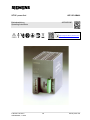
SITOP power flexi
6EP1353-2BA00
Betriebsanleitung A5E38522987
Operating Instructions
https://support.industry.siemens.com

© Siemens AG 2016 2/8 SITOP power flexi
A5E38522987, 11.2016
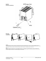
Maßbild
Dimension drawings
SITOP power flexi
Montage
Installation
Hinweis
Diese Betriebsanleitung enthält aus Gründen der Übersichtlichkeit nicht sämtliche Detailinformationen und kann auch nicht jeden denkbaren Fall der Auf-
stellung, des Betriebes oder der Instandhaltung berücksichtigen. Weiterführende Hinweise erhalten Sie über die örtliche Siemens-Niederlassung bzw. über die
Homepage http://www.siemens.de/sitop. Technische Änderungen jederzeit vorbehalten. In Zweifelsfällen gilt der deutsche Text.
Note
These operating instructions cannot claim to cover all details of the product, nor to provide for every possible contingency to be met in connection with
installation, operation or maintenance. For more information, please contact your local Siemens office or consult our Web site http://www.siemens.de/sitop.
Subject to change without prior notice. The German text applies if any doubt exists.
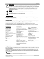
Einstellung U
A
und I
Amax
Adjustment U
A
and I
Amax
+
I
II
I
II
III
I

© Siemens AG 2016 3/8 SITOP power flexi
A5E38522987, 11.2016
Deutsch
WARNHINWEISE
Beim Betrieb elektrischer Geräte stehen zwangsläufig bestimmte Teile dieser Geräte unter gefährlicher Spannung.
Unsachgemäßer Umgang mit diesen Geräten kann deshalb zu Tod oder schweren Körperverletzungen sowie zu erheblichen
Sachschäden führen. Nur entsprechend qualifiziertes Fachpersonal darf an diesem Gerät oder in dessen Nähe arbeiten. Der
einwandfreie und sichere Betrieb dieses Gerätes setzt sachgemäßen Transport, fachgerechte Lagerung, Aufstellung und
Montage voraus.
Vor Beginn der Installations- oder Instandhaltungsarbeiten ist der Hauptschalter der Anlage auszuschalten und gegen
Wiedereinschalten zu sichern. Bei Nichtbeachtung kann das Berühren spannungsführender Teile Tod oder schwere
Körperverletzung zur Folge haben.
ACHTUNG
Elektrostatisch gefährdete Bauelemente (EGB). Nur geschultes Personal darf das Gerät öffnen.
Entsorgungsrichtlinien
Verpackung und Packhilfsmittel sind recyclingfähig und sollten grundsätzlich der Wiederverwertung zugeführt werden.
Das Produkt selbst darf nicht über den Hausmüll entsorgt werden.
Beschreibung und Aufbau
SITOP power flexi ist ein Einbaugerät. Für die Installation des Gerätes sind die einschlägigen DIN/VDE-Bestimmungen oder die
länderspezifischen Vorschriften zu beachten.
Primär getaktete Stromversorgung zum Anschluss an 1phasiges Wechselstromnetz 120 oder 230 V, 50/60 Hz; der Ausgang ist leerlauf-
und kurzschlussfest, potentialfrei und einstellbar.
Technische Funktion
Die Ausgangsspannung des Gerätes kann zwischen 3 V
DC
und 52 V
DC
eingestellt werden. Die Einstellung der Ausgangsspannung erfolgt
über Potentiometer U
A
an der Frontseite (Position siehe Seite 2) oder extern über Klemmen X2-2 (siehe Seite 4).
Das Gerät arbeitet im Ausgangsspannungsbereich 3 bis12 V
DC
mit einem max. Ausgangsstrom von 10A,
im Ausgangsspannungsbereich 12 bis 52 V
DC
wird die Abgabeleistung auf max. 120 W begrenzt (siehe Kennlinie Seite 4).
Die Strombegrenzung kann zwischen 2 A und 10 A eingestellt werden. Die Einstellung der Strombegrenzung erfolgt über Potentiometer
I
Amax
(Position siehe Seite 2) oder extern über Klemmen X2-12 (siehe Seite 4).
Technische Daten
Eingangsgrößen
Eingangsnennspannung:
AC 120/230V, 50/60Hz
Arbeitsspannungsbereich:
85-132V 170-264V
Überspannungsfest nach:
EN 61000-4-1 A.2
Wirkungsgrad bei Volllast und 230V:
> 75%
Einschaltstrombegrenzung (25°C) serienmäßig
bei 230V:
< 32A, 0,8A
2
s
Netzseitig empfohlener LS-Schalter
6A Charakteristik C.
Eingangsstrom bei 120/230V:
2,2/1,3A
Leistungsaufnahme:
138W
Gewicht
0,75kg
Ausgangsgrößen
Ausgangsgleichspannung:
Auslieferzustand: 24V ±1% (Nennspannung),
einstellbar mittels Schraubendreher an Potentiometer
U
A
(Gerätevorderseite, Position siehe Seite2) im
Bereich 3 bis 52V
Welligkeit der Ausgangsspannung:
< 50 mV
ss
Restwelligkeit
< 100 V
ss
Schaltspitzen
Ausgangsgleichstrom:
max 10A (im Bereich 3...12V)
Ausgangsleistung:
max. 120W (im Bereich 12...52 V)
Ausgangsstrombegrenzung:
Auslieferzustand:10A ±10%,
einstellbar mittels Schraubendreher an Potentiometer
I
Amax
(Gerätevorderseite, Position siehe Seite2) im
Bereich 2 bis 10A
Umgebung
Temperatur
für Lagerung und Transport: -40 bis +85°C
für Betrieb von 90-132V und 180-264V; 0 bis +60°C
für Betrieb von 170-180V, Derating von t
amb
+1K/V
AC
für Betrieb von 85-90V , Derating von t
amb
+2K/ V
AC
Feuchteklasse:
entsprechend Klimaklasse 3K3 nach EN 60721
Verschmutzungsgrad 2
Luftselbstkühlung
Schutz- und Überwachungs-
funktion
statische Leistungsbegrenzung: typ. 1,1 x P
nenn
Verhalten im Kurzschlussfall (Ausgang):
selbsttätiger Wiederhochlauf
Netzausfallüberbrückung bei Eingangsspannung
93/187V und Ausgangsleistung 120W:
>10ms
eingebaute Sicherung:
T 3,15A/250V
Vorschriften
Schutzart: IP20 nach EN 60529
Schutzklasse: 1 nach EN 61140
Sicherheit nach EN 60950-1: SELV
Störaussendung: nach EN 61000-6-3, funkentstört
nach EN 55022, Grenzwertkurve B
Störfestigkeit: nach EN 61000-6-2
Begrenzung der Eingangsstromoberwellen nach
EN 61000-3-2 Klasse D
cULus (UL 508), File E143289
Montagehinweise
Montage auf Normprofilschiene DIN EN 50022-35x15/7,5. Das Gerät ist zwecks ordnungsgemäßer Entwärmung vertikal so zu montieren,
dass die Eingangsklemmen und die Ausgangsklemmen unten sind. Unterhalb und oberhalb des Gerätes soll mindestens ein Freiraum von
je 50 mm eingehalten werden.
Der Anschluss der Versorgungsspannung (AC 120/230 V) und der notwendigen Brücke für den 120 V Bereich muss gemäß VDE 0100 und
VDE 0160 ausgeführt werden. Eine Schutzeinrichtung (Sicherung) und Trenneinrichtung zum Freischalten der Stromversorgung muss
vorgesehen werden. Beim Betrieb des Gerätes im 120 V Bereich muss eine Brücke zwischen den beiden „AC 120 V-JUMPER”-Klemmen
verdrahtet werden. Diese muss hinsichtlich Querschnitt und Isolation wie die Netzanschlussleitungen beschaffen sein. Die Länge darf
100mm nicht überschreiten.
Warnung: Auch die notwendige Brücke führt gefährliche elektrische Spannung!
!
!

© Siemens AG 2016 4/8 SITOP power flexi
A5E38522987, 11.2016
Deutsch
Signalisierung
LED leuchtet nicht Keine Netzspannung (z.B. vorgeschaltete Schutzeinrichtung hat ausgeschaltet) oder Gerät defekt.
LED leuchtet grün Die Ausgangsspannung liegt innerhalb der Toleranz.
LED leuchtet rot Das Gerät arbeitet in der Strombegrenzung (max. 10A) oder in der Leistungsbegrenzung (max. 120W).
Anschluss- und Klemmenbelegung von X1 (Anschlusswert: 0,5...2,5mm
2
oder 25...15AWG)
Klemme
Bezeichnung
Funktion
X1-1
L1
Eingangsspannung AC 120/230V
X1-2
N
X1-3
PE
Schutzleiter
X1-4
AC 120V -
Notwendige Brücke für den Arbeitsbereich AC 85…132 V
X1-5
Jumper
X1-6
⊕ L+
Ausgangsspannung 3 - 52 V,
Ausgangsstrom max. 10 A (im Bereich 3...12 V), Ausgangsleistung max. 120 W (im Bereich 12...52 V),
siehe Abbildung Ausgangskennlinie
X1-7
⊖ M
X1-8
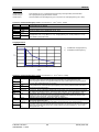
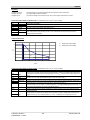
Ausgangskennlinie
Anschluss- und Klemmenbelegung von X2 (Anschlusswert: 0,14...1,5mm
2
oder 25...15 AWG)
Klemme
Bezeichnung
Funktion
X2-1
(Brücke 1)
┐
┘
U
soll
Bei bestückter Brücke (Auslieferzustand) Einstellung der Ausgangsspannung über Potentiometer U
A
(Frontseite) möglich. Bei nicht bestückter Brücke Ferneinstellung der Ausgangsspannung über
Spannungssignal an Klemme X2-2 (Signalmasse Klemme X2-9); hierbei entspricht ein Spannungssignal
0 - 2,5V
DC
einer Ausgangsspannung von 0 - 52V
DC
.
X2-2
X2-3
Sense +
Senseleitungs-Anschluss: Ermöglicht die Kompensation von Spannungsabfällen infolge
Leitungswiderständen. Maximale Spannungsausregelung 0,5V je Leitung. Weitere Hinweise siehe Abb. 2
Sense-Leitungs-Anschluss (Seite 7).
X2-4
Sense −
X2-5
UH
Klemme derzeit nicht belegt (ohne Funktion)
X2-6
Power Good
Power Good - Signal: Potentialfreier Relaiskontakt ist geschlossen wenn die Ausgangsspannung innerhalb
der Toleranz liegt (Ruhestromprinzip). Technische Funktion siehe Abb. 1 Zeit-Impuls-Diagramm (Seite 7).
X2-7
X2-8
Reset
Reset-Signal: Open-Collector (30V, 20mA); wird aktiviert bei Unterschreiten der Mindestspannung am
Eingang und mind. 1ms vor Einbruch der Ausgangsspannung abgegeben (Signalmasse Klemme X2-9).
Technische Funktion siehe Abb. 1 Zeit-Impuls-Diagramm (Seite 7).
X2-9
Ground
Masseanschluss für Signale an Klemme X2-2, X2-8, X2-10 oder X2-12.
X2-10
I
ist
Strommonitorsignal: 2,5V entsprechen typisch einem Ausgangsstrom von 10A +/- 5% über den gesamten
Strombereich (Signalmasse X2-9).
X2-11
(Brücke 2)
┐
┘
I
soll
Bei bestückter Brücke (Auslieferzustand) Einstellung des Ausgangsstrom über Potentiometer I
Amax
(Frontseite) möglich. Bei nicht bestückter Brücke Ferneinstellung der Stromgrenze über Spannungssignal an
Klemme X2-12 (Signalmasse Klemme X2-9); hierbei entspricht ein Spannungssignal 0,5 - 2,5V
DC
einer
Stromgrenze von 2 - 10A.
X2-12
0
10
20
30
40
50
60
0 2 4 6 8 10 12
Volt
Ampere
1 )
2 )
1) Einstellbereich Ausgangsspannung
2) Einstellbereich Strombegrenzung

© Siemens AG 2016 5/8 SITOP power flexi
A5E38522987, 11.2016
English
WARNING
Hazardous voltages are present in this electrical equipment during operation. Failure to properly maintain the equipment can
result in death, severe personal injury or substantial property damage. Only qualified personnel is allowed to work on or
around this equipment. The successful and safe operation of this equipment is dependent on proper handling, installation
and operation.
The mains switch has to be switched off and prevented from being switched on again before installation or maintenance. If
these rules are not adhered to, contact with live parts or improper use can result in death or severe personal injury.
CAUTION
Electrostatic sensitive devices (ESD). Only trained personnel are permitted to open the device.
Disposal guideline
Packaging and packing aids can be recycled and should always be disposed of for reuse.
The product itself shall not be disposed of as normal domestic waste.
Description and design
The SITOP flexi power supply is a rail-mounted built-in unit. The relevant DIN/VDE regulations or equivalent local regulations must be
observed during installation.
Primary switched-mode power supply for connection to 120 or 230 V, 50/60 Hz single-phase AC system; the output is potential-free,
protected against short-circuit and open-circuit conditions and adjustable.
Technical method of operation
The output voltage of the device can be set to between 3 V
DC
and 52 V
DC
. The output voltage is adjusted by means of a potentiometer U
A
on the front (see page 2 for position) or externally by means of terminals X2-2 (see page 6).
The device works in the output voltage range from 3 to 12 V
DC
with a max. output current of 10 A.
In the output voltage range 12 to 52 V
DC
, the power output is limited to a maximum of 120 W (see characteristic curve, page 6).
The current can be limited to between 2 A and 10 A. Current limitation is set by means of a potentiometer I
Amax
(see page 2 for position) or
externally by means of terminals X2-12 (see page 6).
Technical data
Input variables
Input voltage:
AC 120/230V, 50/60Hz
Tolerance:
85-132V 170-264V
Overvoltage proof:
acc. to EN 61000-4-1 A.2
Efficiency at full load and 230 V:
> 75%
Limitation of inrush current(25°C) standard
at 230 V:
< 32A, 0.8A
2
s
Recommended circuit-breaker on supply side
6A characteristic. C.
Input current at 120/230 V:
2.2/1.3A
Power consumption:
138 W
Weight
0.75kg
Output variables
DC output voltage:
As delivered conditions: 24 V ±1% (rated voltage),
adjustable by means of screwdriver at potentiometer
U
A
(front of device. For position, see page2) in the range 3
to 52 V
Ripple content of output voltage:
< 50 mV
ss
ripple
< 100 V
ss
spikes
DC output current:
max. 10 A (in the range 3 to 12 V)
Output power:
max. 120 W (in the range 12 to 52 V)
Output-current limitation:
As delivered condition:10 A ±10%,
adjustable by means of screwdriver at potentiometer
I
Amax
(front of device. For position, see page 2) in the
range 2 to 10 A.
Environment
Temperature
For storage and transport: -40 to +85 °C
For operation from 97-132 V and 195-264 V: 0 to +60°C
For operation from 170-180 V: derating t
amb
+1K / V
AC
for operation from 85-90 V: derating t
amb
+2K / V
AC
Humidity class :
acc. to EN 60721 class 3K3
Pollution degree 2
Natural air convection cooling
Protection and monitoring function
Current limitation: typ. 1.1 x P
rat
Response to short-circuit (output):
automatic restart
Mains buffering time:
>10 ms at input voltage of 93/187 V and output
power of 120 W
Built-in fuse:
T 3,15A/250V
Regulations
Degree of protection: IP20 to EN 60529
Protection class: 1 to EN 61140
Safety to EN 60950-1: SELV
Emission: acc. to EN 61000-6-3, RI suppression
acc. to EN 55022, limit curve B
Noise Immunity: acc. to EN 61000-6-2
Limitation of input-current harmonics:
acc. to EN 61000-3-2 Class D
cULus (UL 508), File E143289
Installation notes
Mounting on standard mounting rails to DIN EN 50022-35x15/7,5. To ensure adequate cooling, the device must be installed vertically, with
the input and output terminals at the bottom. Be sure to leave a minimum free space of 50 mm (2 in.) above and below the device.
The supply voltage (AC 120/230 V) and necessary jumper for the 120 V range must be connected in accordance with VDE 0100 and VDE
0160. A protective device (fuse) and an isolating device for disconnecting the power supply must be provided. If the equipment is operated
in the 120 V range, a jumper must be wired between the two "AC120 V-JUMPER"-terminals. It must have the same cross-section and
insulation as the power supply cables. It must not be longer than 100 mm (4 in.).
WARNING: The necessary jumper also carries dangerous electrical voltage!
!
!

© Siemens AG 2016 6/8 SITOP power flexi
A5E38522987, 11.2016
English
Signalling
LED does not light up No supply voltage (e.g. upstream protection device has opened) or device is defective.
LED lights up green The output voltage is within the tolerance.
LED lights up red The device is working at the current limit (max. 10 A) or at the power output limit (max. 120 W).
Connection and terminal assignment of X1 (connected load: 0.5 to 2.5 mm
2
or 25 to 15 AWG)
Terminal
Designation
Function
X1-1
L1
Input voltage AC 120/230 V
X1-2
N
X1-3
PE
Protective conductor
X1-4
AC 120V -
Necessary jumper for the working range AC 85 to 132 V
X1-5
Jumper
X1-6
⊕ L+
Output voltage 3 to 52 V,
Max. output current 10 A (in the range 3 to 12 V), max. output power 120 W (in the range 12 to 52 V),
see figure output characteristic
X1-7
⊖ M
X1-8
Output characteristic
Connection and terminal assignment of X2 (connected load: 0.14 to 1.5 mm
2
or 25 to 15 AWG)
Terminal
Designation
Function
X2-1
(Jumper 1)
┐
┘
U
soll
If the jumper is fitted (as-delivered status), output voltage can be set by means of the potentiometer U
A
(front). If jumper not fitted, remote setting of the output voltage by means of the voltage signal at terminal X2-
2 (signal ground terminal X2-9); here, a voltage signal of 0 to 2.5 V
DC
corresponds to an output voltage of 0 to
52 V
DC
.
X2-2
X2-3
Sense +
Sense cable connection: enables compensation of voltage drops due to cable resistance. Maximum voltage
correction 0.5 V per cable. More details see figure 2 sense connection (page 7).
X2-4
Sense −
X2-5
UH
Terminal not assigned at the present time (without any function)
X2-6
Power Good
Power-good signal: floating relay contact is closed if the output voltage is within the tolerance (closed-circuit-
current principle). For technical functioning see figure 1 timing-diagram (page 7)
X2-7
X2-8
Reset
Reset signal: Open-collector (30 V, 20 mA); is activated when the voltage at the input falls below the
minimum voltage and is set at least 1 ms before breakdown of the output voltage (signal ground terminal X
2-9). For technical functioning see figure1 timing diagram (page 7).
X2-9
Ground
Ground connection for signals at terminal X2-2, X2-8, X2-10 or X2-12.
X2-10
I
ist
Current monitor signal: 2.5 V typically correspond to an output current of 10 A +/- 5% in total current range
(signal ground X2-9).
X2-11
(Jumper 2)
┐
┘I
soll
If the jumper is fitted (as-delivered status), output voltage can be set by means of the potentiometer I
Amax
(front). If jumper is not fitted, remote setting of the current limit by means of voltage signal at terminal X2-12
(signal ground X2-9); here, a voltage signal of 0.5 - 2.5 V
DC
corresponds to a current limit of 2 to 10 A.
X2-12
0
10
20
30
40
50
60
0 2 4 6 8 10 12
Volt
Ampere
1 )
2 )
1) Setting range output voltage
2) Setting range current limiting

© Siemens AG 2016 7/8 SITOP power flexi
A5E38522987, 11.2016
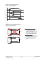
Abbildung 1: Zeit-Impuls-Diagramm
Figure 1: Timing diagramm
Abblidung 2: Sense-Leitungs-Anschluss
Figure 2: Sense connection
L +
sense +
sense -
M
Load
L +
sense +
sense -
M
Load
contact X2-6/7 open
contact X2-6/7 closed
signal X2-8 high
signal X2-8 low
typ. 150V (75V) AC
Ue
Ua
Power
Good
Reset
Hinweise zum Sense-Leitungs-Anschluss:
1) max. Spannungsausregelung 0,5V je Leitung,
d.h. der Lastleitungsquerschnitt ist so zu
wählen, das der Spannungsabfall bei Volllast
je Leitung max. 0,5V beträgt
2) bei Verwendung eines Schaltelements in der
Lastleitung müssen Lastleitung und Sense-
Leitung gemeinsam weggeschaltet werden
Note for connecting sense-line:
1) max. voltage correction 0.5 V per load line, so
ensure that less than 0,5V is dropped in each
load line at full load operation
2) if using switching device in load line, load
line and sense line must be turned off in
common
max. 0,5V
max. 0,5V

© Siemens AG 2016 8/8 SITOP power flexi
A5E38522987, 11.2016
© Siemens AG Österreich, AT-1210 Vienna, Austria. All rights reserved.
Liefermöglichkeiten und technische Änderungen vorbehalten
Availability and technical specifications subject to change without prior notice
-
 1
1
-
 2
2
-
 3
3
-
 4
4
-
 5
5
-
 6
6
-
 7
7
-
 8
8


Siemens SITOP power flexi Operating Instructions Manual
- Typ
- Operating Instructions Manual
in anderen Sprachen
- English: Siemens SITOP power flexi
Andere Dokumente
-
OJ Electronics OJ-FC Bedienungsanleitung
-
Eurotherm 2500P - 2A5 Bedienungsanleitung
-
-
 Stahl ISpac 9162 Operating Instructions Manual
-
ABB DCS550-S02 Quick Manual
-
Perle TRIO-PS/1AC/48DC/10 Installationsanleitung
-
-
-
red lion PAX ANALOG Benutzerhandbuch
-
 MERLIN GERIN IH MULTI 9 Bedienungsanleitung

