
User’s Manual / Benutzerhandbuch
BCD-1000 Series
Customer Display / Kundendisplay
Rev. 1.00
http://www.samsungminiprinters.com

User’s Manual (English)
BCD-1000 Series
Customer Display
Rev. 1.00
http://www.samsungminiprinters.com

Rev. 1.00
-2-
BCD-1000 Series
English
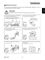
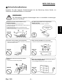
■ Safety Precautions
In using the present appliance, please keep the following safety regulations in order to
prevent any hazard or material damage.
WARNING
Violating following instructions can cause serious injury or death.
Do not bend the cable by force or leave it under any
heavy object.
• A damaged cable can cause a fire.
Do not plug in or unplug with your hands wet.
• You can be electrocuted.
Keep the plastic bag out of children’s reach.
• If not, a child may put the bag on his head.
Do not pull the cable to unplug.
• This can damage the cable, which is the origin of a fire or a
breakdown of the printer.
You must use only the supplied adapter.
• It is dangerous to use other adapters.
Do not plug several products in one multi-outlet.
• This can provoke over-heating and a fire.
• If the plug is wet or dirty, dry or wipe it before usage.
• If the plug does not fit perfectly with the outlet, do not plug in.
• Be sure to use only standardized multi-outlets.
PROHIBITED
PROHIBITED
PROHIBITED
PROHIBITED
PROHIBITED
ONLY SUPPLIED ADAPTER
PROHIBITED

Rev. 1.00
-3-
BCD-1000 Series
English
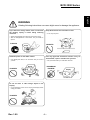
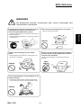
WARNING
Violating following instructions can cause slight wound or damage the appliance.
Do not let water or other foreign objects in the
Display.
• If this happened, switch off and unplug the Display before
calling your dealer.
Use only approved accessories and do not try to
disassemble, repair or remodel it for yourself.
• Call your dealer when you need these services.
Install the printer on the stable surface.
• If the Display falls down, it can be broken and you can hurt
yourself.
Keep the desiccant out of children’s reach.
• If not, they may eat it.
If you observe a strange smoke, odor or noise from
the Display, unplug it before taking following
measures.
• Switch off the Display and unplug the set from the mains.
• After the disappearance of the smoke, call your dealer to
repair it.
TO UNPLUG
PROHIBITED
DISASSEMBLING
PROHIBITED
PROHIBITED
PROHIBITED
Display
Display
Display
Display

Rev. 1.00
-4-
BCD-1000 Series
English
■ Warning - U.S.A
This equipment has been tested and found to comply with the limits for a Class A digital
device pursuant to Part 15 of the FCC Rules. These limits are designed to provide
reasonable protection against harmful interference when the equipment is operated in a
commercial environment. This equipment generates uses, and can radiate radio frequency
energy and if not installed and used according to the instruction manual, may cause
harmful interference to radio communications. Operation of this equipment in a residential
area is likely to cause harmful interference in which case the user will be required to
correct the interference at his/her own expense.
1. The VFD on the Display Unit is sensitive to shock.
Any jarring, throwing, or dropping of the product package can easily result in product
damage and malfunction. Please exercise care in handling.
2. Make sure to use the main cable and power unit included in the product package. Any
use of other such products can result in damage and shortening of product life.
3. The VFD Module is highly susceptible to damage from static electricity. For any product
servicing that requires product disassembly, make sure to place aluminum or copper foil
and/or conductive foam on the conductor surface during work.
4. Use of any freon-based chemical products is strictly prohibited. Any use of a freon-
based spray can cause a static electrical charge that can damage the product.
5. Users are encouraged to carefully review all precautions and warning indications for
product installation and use.
■ Waste Electrical and Electric Equipment (WEEE)
This marking shown on the product or its literature, indicates that is should not
be disposed with other household wastes at the end of its working life, To
prevent possible harm to the environment or human health from uncontrolled
waste disposal, please separate this from other types of wastes and recycle it
responsibly to promote the sustainable reuse of material resources. Household
users should contact either the retailer where they purchased this product, or
their local government office, for details of where and how they can take this item for
environmentally safe recycling. Business users should contact their supplier and check the
terms and conditions of the purchase contract. This product should not be mixed with other
commercial wastes for disposal.

Rev. 1.00
-5-
BCD-1000 Series
English
■ Table of Contents
1. Complete Product Configuration .................................................................................. 6
1-1 Diagrams by Product Type.......................................................................................... 6
1-2 Pre-Installation Precautions......................................................................................... 6
2. Unpacking........................................................................................................................ 7
2-1 BCD-1000D Type ........................................................................................................ 7
2-2 BCD-1000DN Type...................................................................................................... 7
2-3 BCD-1000W Type........................................................................................................ 8
2-4 BCD-1000WN Type..................................................................................................... 8
3. Defaults & Options by Product Type ............................................................................ 9
3-1 Serial Type................................................................................................................... 9
3-1-1 Direct Type : Direct connection with the VFD, bypassing the Board .............. 9
3-1-2 Pass through Type (Data : Host (PC) → VFD → Printer) ............................... 9
3-2 USB Type (Host (PC) → VFD, Host → Printer) ........................................................ 10
4. Connection Type & Size ............................................................................................... 11
4-1 BCD-1000D Type ...................................................................................................... 11
4-2 Size............................................................................................................................ 12
4-2-1 Desk Top Type............................................................................................... 12
4-2-2 Wall Mount Type............................................................................................ 12
4-2-3 Etc. ................................................................................................................ 12
5. Function ......................................................................................................................... 13
5-1 Rotation ..................................................................................................................... 13
5-2 Angling....................................................................................................................... 14
6. Connection .................................................................................................................... 15
6-1 Direct Type Pin Connection....................................................................................... 15
6-1-1 Interface Specification ................................................................................... 15
6-1-2 Connector Signal Assignments ..................................................................... 16
6-1-3 Installation Instructions.................................................................................. 17
6-1-4 Signal Assignments (Cable-end DSUB)........................................................ 17
6-1-5 DC Power Jack.............................................................................................. 17
6-2 Serial pin Connection ................................................................................................ 18
6-2-1 Host interface connector ............................................................................... 18
6-2-2 Host interface connector signal assignments ............................................... 18
6-2-3 Printer interface connector ............................................................................ 19
6-2-4 Printer interface connector signal assignments ............................................ 19
7. Switches......................................................................................................................... 20
7-1 Display Switch ........................................................................................................... 20
7-2 DIP switches .............................................................................................................. 20
7-3 Memory Switches ...................................................................................................... 21
8. Power Control ............................................................................................................... 22
8-1 Serial Board ...............................................................................................................22
8-1-1 Jumper1......................................................................................................... 22
8-1-2 Jumper2......................................................................................................... 22
8-2 USB Board................................................................................................................. 23
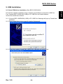
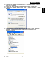
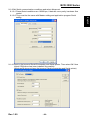
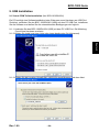
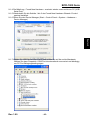
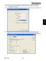
9. USB Installation ............................................................................................................ 24
9-1 Virtual COM driver installation (Only BCD-1000DU/WU).......................................... 24

Rev. 1.00
-6-
BCD-1000 Series
English
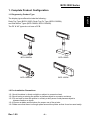
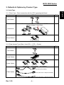
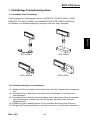
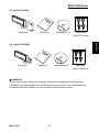
1. Complete Product Configuration
1-1 Diagrams by Product Type
The display types offered include the following :
Desk-Top Type (BCD-1000D), Desk-Top Fix Type (BCD-1000DN),
and Wall Mount Types (BCD-1000W, BCD-1000WN).
The DF & WF types do not have a PCB.
BCD-1000DN
BCD-1000D
BCD-1000WN
BCD-1000W
1-2 Pre-Installation Precautions
1-2-1 Avoid locations in direct sunlight or subject to excessive heat.
1-2-2 Avoid using or storing the printer in places subject to excessive moisture.
1-2-3 Do not use or store the printer in a dusty or dirty area. Avoid places subject to
intense vibration or shock.
1-2-4 Choose a stable and flat place for proper use of the printer.
1-2-5 Make sure that there is enough space around the printer so that it can be used easily.

Rev. 1.00
-7-
BCD-1000 Series
English
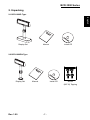
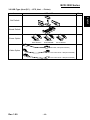
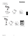
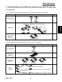
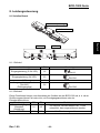
2. Unpacking
2-1 BCD-1000D Type
Display Set Manual Install CD
2-2 BCD-1000DN Type
Display Set Manual Install CD Screw
(M3*10) Tapping

Rev. 1.00
-8-
BCD-1000 Series
English
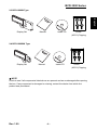
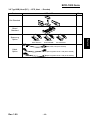
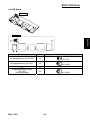
2-3 BCD-1000W Type
Display Set Manual Install CD Screw
(M3*10) Tapping
2-4 BCD-1000WN Type
Display Set Manual Install CD Screw
(M3*10) Tapping
※ NOTE
Check to see if all components listed above are present and are undamaged after opening
the box. If any component is damaged or missing, contact the dealer from which the
product was purchased.

Rev. 1.00
-9-
BCD-1000 Series
English
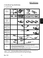
3. Defaults & Options by Product Type
3-1 Serial Type
3-1-1 Direct Type : Direct connection with the VFD, bypassing the Board
Item VFD- Serial Etc
Set Default
Connection
Connection of Serial Jack via separate SMPS
Usage Voltage: 5~24V(2pin)
Power Default
5V (K410-00001A)
3-1-2 Pass through Type (Data : Host (PC) → VFD → Printer)
Item VFD- Serial Etc
Set Default
Board Default
Power Option
24V,2.5A: 24V, 1.5A : 5V
K404-00007A K402-00008B K410-00001A
Cable Option
9PM.25PF (K604-00086A)
Power Cable 3P/3P 1.8M (K610-00005B)
Power Cable 3P/2P 1.8M (K610-00005G)

Rev. 1.00
-10-
BCD-1000 Series
English
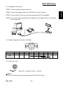
3-2 USB Type (Host (PC) → VFD, Host → Printer)
Item VFD- USB Etc
Set Default
Board Default
Power Option
24V,2.5A: 24V, 1.5A : 5V
K404-00007A K402-00008B K410-00001A
Cable Option
USB Cable,1.8M (K604-00033A)
Power Cable 3P/3P 1.8M (K610-00005B)
Power Cable 3P/2P 1.8M (K610-00005G)

Rev. 1.00
-11-
BCD-1000 Series
English
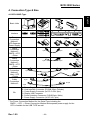
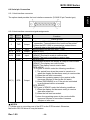
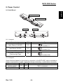
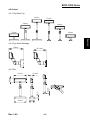
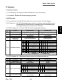
4. Connection Type & Size
4-1 BCD-1000D Type
Basic Units
Interface
A B C D E F
Power
Connection
Method 1
VFD Separate
Power Supply
5~24V
Power
Connection
Method 2
SMPS→VFD
→Pinter
24V
Power
Connection
Method 3
SMPS→VFD
→Pinter
24V
Cable
Connection
Method 1
Host→VFD
→Printer
Cable
Connection
Method 2
Etc
A: Power Supply Connector (Out DC 24V, 3pin)
B: Host Interface Connector (D-SUB 25pin, Female)
C: Power Supply Connector (In DC 5~24V, 2pin)
D: Display Unit Connector
E: Printer Interface Connector (D-SUB 9pin, Male)
F: Power Supply Connector (In DC 24V, 3pin)
* The Power Connection Method for the Serial Type including the
SMPS → VFD → Printer Connection Method and separate power supply for the
VFD is feasible for the USB TYPE as well.
9 pin
25 pin
25 pin
9 pin
9 pin
9 pin
25 pin
25 pin
3 pin 3 pin
2 pin 3 pin

Rev. 1.00
-12-
BCD-1000 Series
English
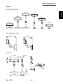
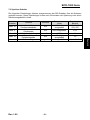
4-2 Size
4-2-1 Desk Top Type
179mm
385mm
533mm
511mm
364mm
158mm
4-2-2 Wall Mount Type
158mm
151.9mm
4-2-3 Etc.
231mm
218mm
105mm
32mm
9.6mm
75.8mm
80mm
47.9mm

Rev. 1.00
-13-
BCD-1000 Series
English
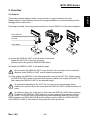
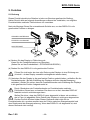
5. Function
5-1 Rotation
This product allows display rotation to any position or angle desired by the user.
Please adhere to the following instructions during installation to prevent possible product
damage and/or malfunction.
Following assembly, follow the sequence below to fix the DISPLAY in the desired position.
(a) (b) (c)
(a) Lower the DISPLAY UNIT in the direction of the arrow.
Rotate the NUT-FIX to allow for lowering.
(Please refer to the product OPEN/CLOSE label.)
(b) Rotate the DISPLAY UNIT to the desired angle.
Do not rotate the DISPLAY UNIT in any direction for more that one full revolution.
(Beware as the DISPLAY UNIT can be rotated continuously.)
(C) After setting the DISPLAY to the desired position, secure the NUT-FIX. (When raising
the DISPLAY UNIT, lateral movement is prevented.) Make sure to tighten the NUT-FIX
after raising the DISPLAY UNIT to the desired height.
As excessive tightening of the NUT-FIX can result in product damage and/or
malfunction, secure only to the extent that the DISPLAY UNIT is fixed and does not
move.
As shown in figure (A), make sure to fully lower the DISPLAY UNIT before rotating.
Rotation of the DISPLAY UNIT when it is not fully lowered will produce a clicking
sound. This sound does not indicate any product breakage and is a result of the
friction between the POLE-MAIN RIB and the rotation section within the POLE-ADJUST.
If the DISPLAY UNIT is fully lowered, this sound will not be produced.
NUT-FIX
POLE-ADJUST
POLE-MAIN

Rev. 1.00
-14-
BCD-1000 Series
English
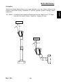
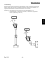
5-2 Angling
This product allows display tilting to any angle desired by the user. Please adhere to the
following instructions during installation to prevent possible product damage and/or
malfunction.
TILT ANGLE : The display can be angled left and right from the Center Line in 13° angle
intervals for a total of 4 steps, 5 positions. (Angling: 52°max.)
Center Line
Center Line

Rev. 1.00
-15-
BCD-1000 Series
English
6. Connection
6-1 Direct Type Pin Connection
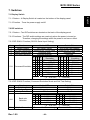
6-1-1 Interface Specification
Signal specifications
Data transmission Serial
Synchronization Synchronous
Handshaking (*) DTR/DSR control
Signal levels MARK = -3 to -15 V
logic = “1” OFF
SPACE = +3 to +15 V logic = “0” ON
Baud Rate (*) 1200, 2400, 4800, 9600, 19200, 38400, 57600, 115200 bps
(bps : bits per second)
Data word length (*) 7 bits, 8 bits
Parity (*) None, odd, even
Stop bits 1 or more
(*) Selected by the DIP switches.

Rev. 1.00
-16-
BCD-1000 Series
English
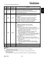
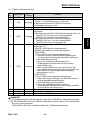
6-1-2 Connector Signal Assignments
Pin
NO
Signal
Name
Signal
Direction
Function
1 FG - Frame ground
2 TXD Output
1) When the BDC-1000 is connected with the data pass
through(*1) : Transmit data to the printer
2) When the BDC-1000 is connected in a stand-alone :
Transmit data to the host
3 RXD Input Receive data from the printer
4 DSR Input
This indicates whether the printer is ready to receive data.
1) When the BCD-1000 is connected with a data pass
through(*1) :
[MARK] : The printer is not ready to receive data
[SPACE] : The printer is ready to receive data
2) When the BDC-1000 is connected in a stand-alone :
[MARK] : The host is not ready to receive data
[SPACE] : The host is ready to receive data
5 DTR Output
This indicates whether the display is ready to receive data
(*2).
[SPACE] The display can receive data.
[MARK] The display cannot receive data.
[DTR MARK]
DTR goes to MARK under the following conditions :
① The period from when the power is turned on to when
the display first becomes ready to receive data.
② When the self-test is executed.
③ When the remaining space in the receive buffer
becomes 40bytes or less (buffer-full state).
④ When [DSR MARK] is on, if the printer is selected by a
peripheral device command. (When the BCD-1000 is
connected with the data pass through.)(*1)
[DTR SPACE]
DTR goes to SPACE under the following conditions :
① When the display first becomes ready to receive data
after power-on.
② When the self-test has ended.
③ When the remaining space in the receive buffer
becomes 50bytes or more after it became 40bytes or
less once.
6 SG - Signal GND
7 PS - Power supply terminal
8 PG - Flyback line for power supply
NOTES※
(*1) For the data pass through and the stand alone, refer to SVC Manual
connection methods for detail.
(*2) [DTR MARK] can be set by the US v command. This case differs from the
above-mentioned.
[DTR MARK] Refer to the US v command in section 4, Command Description.

Rev. 1.00
-17-
BCD-1000 Series
English
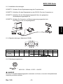
6-1-3 Installation Instructions
STEP1. Turn the computer system power off.
STEP2. Connect the Display Cable to the RS-232 Port of the Computer.
STEP3. Connect the DC Power source by the appropriate DC Power adapter.
STEP4. Turn on the computer and the power supply unit, the display will be on and ready
for receiving data.
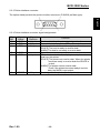
6-1-4 Signal Assignments (Cable-end DSUB)
1 2 3 4 5 6 7 8 9
pin Name NC RXD TXD DTR GND DSR RTS CTS NC
Short
Connection
6-1-5 DC Power Jack
MAX 300 ~ 1350mA. +5VDC ~ +24VDC.
NOTE※
To use 5V DC Power source should modify the PCB Circuit in factory.

Rev. 1.00
-18-
BCD-1000 Series
English
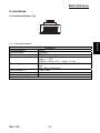
6-2 Serial pin Connection
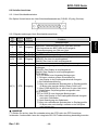
6-2-1 Host interface connector
The option stand provides the host interface connector (D-SUB 25 pin Female type).
6-2-2 Host interface connector signal assignments
Pin
NO
Signal
Name
Signal
Direction
Function
1 FG - Frame ground
2 TXD Output
1) When the BDC-1000 is connected when a passthrough
connection :Transmit data to the host from the printer
2) When the BDC-1000 is connected as a stand-alone :
Transmit data to the host from the DM
3 RXD Input Receive data from the host (host → DM)
4(*1) RTS Output Same as DTR
6(*2) DSR Input
Indicates whether the host is ready to receive data.
[SPACE] The host is ready to receive data.
[MARK] The host is not ready to receive data.
7 GND - Signal ground
20(*1) DTR Output
This indicates whether the display is ready to receive data.
[SPACE] The display can receive data.
[MARK] The display cannot receive data.
[DTR MARK]
DTR goes to MARK under the following conditions :
① The period from when the power is turned on to
when the display first becomes ready to receive data.
② When the self-test is executed.
③ When the remaining space in the receive buffer
becomes 40bytes or less (buffer-full state).
④ When [DSR MARK] is on, if the printer is selected
by a peripheral device command.
[DTR SPACE]
DTR goes to SPACE under the following conditions :
① When the display first becomes ready to receive
data after power-on.
② When the self-test has ended.
③ when the remaining space in the receive buffer
becomes 50bytes or more after it became
40bytes or less once.
NOTES※
(*1) Make sure to use either one of the RTS or the DTR terminal. Otherwise,
the built-in RS-232 driver IC may be broken.

Rev. 1.00
-19-
BCD-1000 Series
English
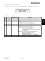
6-2-3 Printer interface connector
The option stand provides the printer interface connector (D-SUB 9 pin Male type).
6-2-4 Printer interface connector signal assignments
Pin
NO
Signal
Name
Signal
Direction
Function
2 RXD Input Receive data from the printer (printer → host)
3 TXD Output Transmit data to the printer (DM → Printer)
4 DTR Output Indicates whether the host is ready to receive data.
[SPACE] The host is ready to receive data.
[MARK] The host is not ready to receive data.
5 GND - Signal
6 DSR Input This indicates whether the display is ready to receive
data from the printer.
[SPACE] The printer can receive data. When the printer
becomes ready to receive data the SPACE is
output.
[MARK] The printer cannot receive data.
Even if the printer becomes readyto receive
data, the MARK is not output.
9 RESET Output Reset signal to the printer (host → printer)
Seite wird geladen ...
Seite wird geladen ...
Seite wird geladen ...
Seite wird geladen ...
Seite wird geladen ...
Seite wird geladen ...
Seite wird geladen ...
Seite wird geladen ...
Seite wird geladen ...
Seite wird geladen ...
Seite wird geladen ...
Seite wird geladen ...
Seite wird geladen ...
Seite wird geladen ...
Seite wird geladen ...
Seite wird geladen ...
Seite wird geladen ...
Seite wird geladen ...
Seite wird geladen ...
Seite wird geladen ...
Seite wird geladen ...
Seite wird geladen ...
Seite wird geladen ...
Seite wird geladen ...
Seite wird geladen ...
Seite wird geladen ...
Seite wird geladen ...
Seite wird geladen ...
Seite wird geladen ...
Seite wird geladen ...
Seite wird geladen ...
Seite wird geladen ...
Seite wird geladen ...
Seite wird geladen ...
-
 1
1
-
 2
2
-
 3
3
-
 4
4
-
 5
5
-
 6
6
-
 7
7
-
 8
8
-
 9
9
-
 10
10
-
 11
11
-
 12
12
-
 13
13
-
 14
14
-
 15
15
-
 16
16
-
 17
17
-
 18
18
-
 19
19
-
 20
20
-
 21
21
-
 22
22
-
 23
23
-
 24
24
-
 25
25
-
 26
26
-
 27
27
-
 28
28
-
 29
29
-
 30
30
-
 31
31
-
 32
32
-
 33
33
-
 34
34
-
 35
35
-
 36
36
-
 37
37
-
 38
38
-
 39
39
-
 40
40
-
 41
41
-
 42
42
-
 43
43
-
 44
44
-
 45
45
-
 46
46
-
 47
47
-
 48
48
-
 49
49
-
 50
50
-
 51
51
-
 52
52
-
 53
53
-
 54
54


Samsung BCD-1000 Benutzerhandbuch
- Typ
- Benutzerhandbuch
- Dieses Handbuch eignet sich auch für
in anderen Sprachen
- English: Samsung BCD-1000 User manual
Andere Dokumente
-
 Magnescale MG30 Bedienungsanleitung
-
MSW MSW-CCW04-B Bedienungsanleitung
-
Citizen CBM1000II RF Benutzerhandbuch
-
-
-
 Boundless VGB10 Benutzerhandbuch
-
 Citizen Systems iDP-460 Benutzerhandbuch
-
Varian 948 Operation And Service Manual
-
SBC PCD2.M5xxx Bedienungsanleitung
-


