Vestfrost FSHG 60 Usage And Installation Manual
- Typ
- Usage And Installation Manual

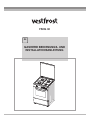
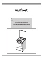
GAS COOKER USAGE
AND INSTALLATION MANUAL
EN
FSHG 60

Dear Customer,
We take offering quality products more than your expectation as goal, offers you
the products produced in modern facilities where each cooker was carefully and
particularly tested for quality.
This leaflet contains all the necessary information for installing and using
your new cooker.
Before you begin using your new cooker, we suggest you read this leaflet carefully
because it contains all the basic information for proper and reliable installation,
proper use and regular maintenance of your cooker. This cooker must be installed
only by a qualified professional in accordance with safety standards and laws.
Never attempt to repair your cooker on your own.
CE Declaration of conformity
This cooker is only for domestic use inside a house (excluding professional use).
Any other use (such as heating a room) is improper and dangerous.
This cooker has been designed, constructed, and marketed incompliance with:
Safety requirements of the "Gas" Directive 2009/142/EC ;
Requirements of the Directive 93/68/EC.

2
CONTENTS
1.
2. WARNINGS
General safety warnings
Installation warnings
During usage
During cleaning and maintenance
3. INSTALLATION
Adjusting the feet
Gas connection
Changing gas
USE OF YOUR PRODUCT
Using gas burners
Using cooktop burners
Accessories used in oven
CLEANING AND MAINTENANCE
Cleaning
Maintenance
SERVICE AND TRANSPORT
Information on transport
TECHNICAL CHARACTERISTICS
Installation environment for your cooker
Installing your cooker
Using the gas oven burner
Requirements before contacting the customer service
3.1
3.2
3.3
3.4
3.5
4.
4.1
4.1.1
4.1.2
4.2
5.
5.1
5.2
6.
6.1
6.2

3
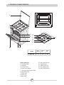
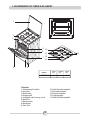
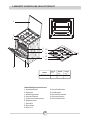
1. TECHNICAL CHARACTERISTICS
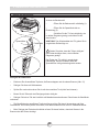
Cooker parts list:
1- Cooktop Cover
2- Cooktop
3- Control Panel
4- Oven Door Handle
5 - Storage compartment door
6- Adjustable feet
7- Oven Door
8- Oven Tray
9-Wire Shelf
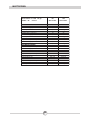
MODEL
FSHG 60 60 60 85
DEPTH-
SIZE(cm)
LENGTH
(cm)
HEIGHT
(cm)
10- Semi-rapid burner
11- Rapid burner
12- Auxiliary burner
13- Pan support grid
14- Semi-rapid burner
10
11
12
13
14
1
2
3
4
5
6
7
8
9

4
2. WARNINGS
READ THESE INSTRUCTIONS CAREFULLY AND COMPLETELY BEFORE USING YOUR
APPLIANCE, AND KEEP IT IN A CONVENIENT PLACE FOR REFERENCE WHEN NECESSARY.
THIS MANUAL IS PREPARED FOR MORE THAN ONE MODEL IN COMMON. YOUR APPLIANCE
MAY NOT HAVE SOME OF THE FEATURES THAT ARE EXPLAINED IN THIS MANUAL. PAY
ATTENTION TO THE EXPRESSIONS THAT HAVE FIGURES, WHILE YOU ARE READING THE
OPERATING MANUAL.
General Safety Warnings
- This appliance is intended for domestic household
use only and should not be used for any other purpose
or in any other application, such as for non-domestic
use or in a commercial environment.
- If the supply cord is damaged, it must be replaced
by the manufacturer, its service agent or similarly
qualified persons in order to avoid a hazard.
- This appliance can be used by children aged
from 8 years and above and persons with
reduced physical, sensory or mental capabilities
or lack of experience and knowledge if they
have been given supervision or instruction
concerning use of the appliance in a safe way
and understand the hazards involved. Children
shall not play with the appliance. Cleaning and
user maintenance shall not be made by children
without supervision.
- WARNING: The appliance and its accessible
parts become hot during use. Care should be
taken to avoid touching heating elements.
Children less than 8 years of age shall be kept
away unless continuously supervised.
- WARNING: Unattended cooking on a hob with

5
2. WARNINGS
fat or oil can be dangerous and may result in
fire. NEVER try to extinguish a fire with water,
but switch off the appliance and then cover
flame e.g. with a lid or a fire blanket.
- WARNING: Danger of fire: do not store items
on the cooking surfaces.
- Any spillage should be removed from the lid
before opening.
- The hob surface should be allowed to cool
before closing the lid.
- The appliance is not intended to be operated
by means of an external timer or separate
remote-control system.
- During use, the appliance becomes hot. Care
should be taken to avoid touching heating
elements inside the oven.
- Do not use harsh abrasive cleaners or sharp
metal scrapers to clean the oven door glass
since they can scratch the surface, which may
result in shattering of the glass.
- Do not use steam cleaners for cleaning the
appliance.
- CAUTION: Accessible parts may become hot
during use. Young children should be kept
away.
• Your appliance is produced in accordance with all applicable local and international
standards and regulations.

6
2. . WARNINGS
• Maintenance and repair work must be made only by authorised service technicians.
Installation and repair work that is carried out by unauthorised technicians may endanger
you. It is dangerous to alter or modify the specifications of the appliance in any way.
• Prior to installation, ensure that the local distribution conditions (nature of the gas and
gas pressure) and the requirements of the appliance are compatible. The requirements for
this appliance are stated on the label.
• Do not try to lift or move the appliance by pulling the door handle.
• This appliance is not connected to a combustion products evacuation device. It shall be
installed and connected in accordance with current installation regulations. Particular
attention shall be given to the relevant requirements regarding ventilation.
• If after 15 s the burner has not lit, stop operating the device and open the kitchen door
or window and/or wait at least 1 min before attempting a further ignition of the burner.
• These instructions are only valid if the country symbol appears on the appliance. If the
symbol does not appear on the appliance, it is necessary to refer to the technical
instructions which will provide the necessary instructions concerning modification of the
appliance to the conditions of use of the country.
• All possible security measures have been taken to ensure your safety. Since the glass
may break, you should be careful while cleaning to avoid scratching. Avoid hitting or
knocking on the glass with accessories.
• While the oven door is open, do not let children climb on the door or sit on it.
Installation Warnings
• Do not operate the appliance before it is fully installed.
• The appliance must be installed by an authorised technician and put into use. The
producer is not responsible for any damage that might be caused by defective placement
and installation by unauthorised people.
• When you unpack the appliance, make sure that has not been damaged during
transportation. In case of any defect; do not use the appliance and contact a qualified
service agent immediately. As the materials used for packaging (nylon, staplers,
styrofoam...etc) may cause harmful effects to children, they should be collected and
removed immediately.
• Protect your appliance against atmospheric effects. Do not expose it to effects such as sun,
rain, snow etc.
• The surrounding materials of the appliance (cabinet) must be able to withstand a
temperature of min 100°C.
During usage
• When you first run your oven a certain smell will emanate from the insulation materials.
For this reason, before using your oven, run it empty at maximum temperature for 45
minutes. At the same time you need to properly ventilate the environment in which the
product is installed.
• During usage, the outer and inner surfaces of the oven get hot. While opening the oven
door, step back to avoid the hot steam coming out of the oven. There may be a risk of
burns.
• Do not put flammable or combustible materials, in or near the appliance when it is
operating.
• Always use oven gloves to remove and replace food in the oven.

• Do not leave the cooker while cooking with solid or liquid oils. They may catch fire on
condition of extreme heating. Never pour water on to flames that are caused by oil. Cover
the saucepan or frypan with its cover in order to choke the flame that has occured in this case
and turn the cooker off.
• Always position pans over the centre of the cooking zone, and turn the handles to a safe
position so they cannot be knocked or grabbed.
• If you will not use the appliance for a long time, plug it off. Keep the main control switch off. Also when
you do not use the appliance, keep the gas valve off.
• Make sure the appliance control knobs are always in the "0" (stop) position when it is not used.
• The trays incline when pulled out. Be careful not to let hot liquid spill over.
• CAUTION: The use of a gas cooking appliance results in the production of heat, moisture and products
of combustion in the room in which it is installed. Ensure that the kitchen is well ventilated especially
when the appliance is in use, keep natural ventilation holes open or install a mechanical ventilation
device (mechanical extractor hood).
• Prolonged intensive use of the appliance may call for additional ventilation, for example opening of
a window, or more effective ventilation, for example increasing the level of mechanical ventilation
where present.
• CAUTION:
Turn off all the burners before shutting the lid.
The hob surface should be allowed to cool before closing the lid.
• When the door or drawer of the oven is open, do not leave anything on it. You may unbalance your
appliance or break the cover.
• Do not put heavy things or flammable or ignitable goods (nylon, plastic bag, paper, cloth...etc) into
the drawer. This includes cookware with plastic accessories (e.g. handles).
During cleaning and maintenance
• Always turn the appliance off before operations such as cleaning or maintenance. You can do it
after plugging the appliance off or turning the main switches off.
• Do not remove the control knobs to clean the control panel.
TO MAINTAIN THE EFFICIENCY AND SAFETY OF YOUR APPLIANCE, WE RECOMMEND YOU
ALWAYS USE ORIGINAL SPARE PARTS AND TO CALL ONLY OUR AUTHORISED
SERVICE AGENTS IN CASE OF NEED.
7
2. . WARNINGS

8
3. INSTALLATION
This modern, functional and practical cooker that was manufactured with the parts and materials
of highest quality will meet your cooking needs in every aspect. Before using your cooker, please
read this leaflet carefully to find out all its functions and achieve the best possible results. For
proper installation, consider the following recommendations to avoid any problem or
dangerous situation. They must also be read by the technician who will install the cooker.
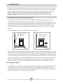
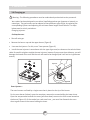
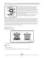
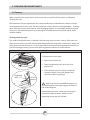
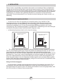
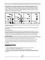
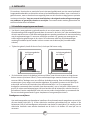
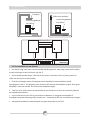
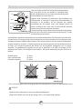
3.1 Installation environment for your cooker
Your cooker must be set up and used in a place where it will always have ventilation. Gas
combustion is made possible by the oxygen in the air. It is therefore necessary that the air be
renewed and that combustion products be discharged in accordance with the regulations. There
must be a natural ventilation enough to provide the gas to be used in the environment. The
airflow must enter via vents installed on walls in direct contact with the outside (see diagram
below).
While operating, this cooker needs 2m3 /h air per kw input.
•
•
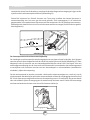
• The airflow must enter through the bottom (minimum 100cm ²) and come out on top (minimum
100cm ²). These vents must therefore have a minimum area of 100 cm2 for the effective passage
of air. These vents should be open and never closed. They should preferably be located near the
rear of the cooker (for the air inlet Fig. 1 and 2) and opposite the burnt gases caused by cooking
(for evacuation) that is to say at least 1.80m above the ground. If you cannot open these vents
toto the outside, where the cooker is installed, the necessary air may also come from another
location provided it is properly ventilated and is neither a bedroom nor a dangerous place.
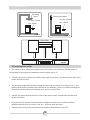
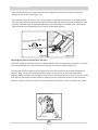
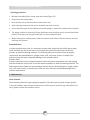
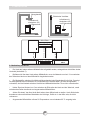
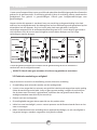
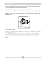
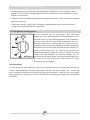
Evacuating burnt gases
It is advisable to install either an exhaust hood directly connected to a pipe leading directly to the
outside (Fig. 3), or an electrical ventilator installed on the window or outside wall (Fig. 4) to
evacuate flue gases directly outside. The electrical ventilator power supply must be calculated in
order to renew the air in the kitchen 4-5 times per hour.
Air inlet section
2
min. 100cm
Air inlet section
2
min. 100cm
Figure 1
Figure 2

9
3. INSTALLATION
Extracting
hood
Electrical ventilator
Air inlet section
2
min. 100cm
Air inlet section
2
min. 100cm
Figure 3
Figure 4
•
•
•
•
•
•
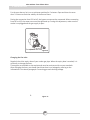
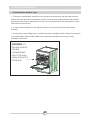
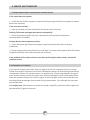
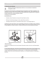
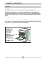
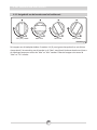
3.2 Installing your cooker
The cooker may be placed near another piece of furniture, but make sure that the height of
surrounding furniture does not exceed the cooker height (see fig. 5).
If kitchen furniture are above the cooker, leave a space of at least 10cm between the sides of the
cooker and the furniture.
The minimum height between the cooktop and the hood (or wall units) is shown in Fig. 5. The
exhaust hood must be located at least 65cm from the cooktop. If there is no hood, the height of
.
the furniture located above the cooktop must not be less than 70cm
Leave a 2cm space between the rear of the cooker and the wall, and between the sides and
adjacent furniture.
Pay attention not to place the cooker near a refrigerator; there must be no flammable or
ignitable materials such as curtain, cloth, etc... that may easily get burnt.
Adjacent furniture must be manufactured resistant to temperatures up to 90°C.
Figure 5
Min. 60cm
COOKER HOOD
Min. 42cm
Min. 42cm
Min. 65cm (with hood)
Min. 70cm (without hood )

3. INSTALLATION
Figure 6
9
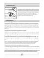
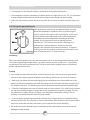
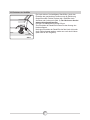
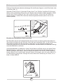
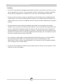
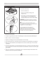
3.3 Adjustment of feet
.
3.4 Gas connection
Your stands on 4 adjustable feet. When the is
placed where to be used, check if the product is balanced. If it
is not balanced, you can make the adjustment by turning the
feet clockwise if required. It is possible to raise the appliance
maximum 30mm by the feet. If the feet are adjusted
appropriately, it is required not to move the appliance by
dragging, it should be moved by lifting it up
Assembly of gas supply and leakage check
The connection of the appliance should be performed in accordance with local and international
standards and regulations applicable. You can find the information related to appropriate gas types
and appropriate gas injectors on technical data table. If the pressure of used gas is different than
these values stated or not stable in your area, it may be required to assemble an available pressure
regulator on the gas inlet. It is certainly required to contact to the authorized service to make these
adjusments.
The points that must be checked during flexible hose assembly
If the gas connection is made by a flexible hose that is fixed on the gas inlet of appliance, it must be
fixed by a pipe collar as well. Connect your appliance with a short and durable hose that is as close
as possible to the gas source. The hose's permitted maximum lenght is 1.5m. The hose that brings
gas to the appliance must be changed once a year for your safety.
0
The hose must be kept clear from areas that may heat up to temperatures in excess of 90 C. The
hose must not be ruptured, bent or folded. It must be kept clear of sharp corners, moving things,
and should not be defective. Before assembly, it must be checked whether there is any production
defect.
As gas is turned on, all connection parts and hose must be checked with soapy water or leakage
fluids. Do not use naked flame to check gas leakage. All metal components used during gas
connection must be clear of rust. Also check the expiry dates of components to be used.
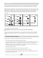
The points that must be checked during fixed gas connection assembly
To assemble a fixed gas connection (gas connection made by threads, e.g. a nut), there are different
methods used in different countries. The most common parts are already supplied with your appliance.
Any other part can be supplied as spare part.
During connections always keep the nut on the gas manifold fixed, while rotating the counter-part. Use
spanners of appropriate size for safe connection. For all surfaces between different components,
product product

3. INSTALLATION
10
always use the seals provided in the gas conversion kit. The seals used during connection should
also be approved to be used in gas connections. Do not use plumbing seals for gas connections.
Remember that this appliance is ready to be connected to gas supply in the country for which it has
been produced. The main country of destination is marked on the rear cover of the appliance. If you
need to use it in another country, any of the connections in the figure below can be required. In
such a case, learn the appropriate connection parts and obtain those parts to perform a safe
connection.
It is required to call the authorized service to be able to make the gas connections appropriately
and in compliance with safety standards.
Surely do not use any match or lighter for control of gas leakage
The gas inlet of this product is on the right side of the appliance. If connection point needs to be
moved to the left side of the appliance, you can request an extension pipe from your authorized
service.
During the electric connection, follow the instructions stated in the user manual
The earthing cable must be connected to the earth terminal
You have to ensure the power cord with suitable insulation to be connected to the power source
during the connection If there is no appropriate earthed electric outlet in accordance with
regulations in the place where the appliance to be installed, contact to our authorized service.
The earthed electric outlet must be close to the appliance.
Do not use an extension cord
The power cord must not touch to the hot surface of the product.
In case the cord is damaged, contact Authorized Service to have it changed
Any wrong electric connection may damage your appliance, as well as endangering your safety,
rendering your guarantee invalid
ATTENTION! .
3.5 Electric connection and safety
.
• .
•
.
• .
•
• .
•
.
Adapter
Gas Pipe Gas Pipe Gas Pipe Gas Pipe
Seal
Seal
Seal
Hose
Fitting
Gas Hose
with Collar
Mechanical
Gas Hose
Mechanical
Gas Hose
Mechanical
Gas Hose

12
•
•
•
•
3.6 Changing gas
Warning : The following procedures must be undertaken by authorised service personnel.
Your cooker has been designed to use either liquefied petroleum gas (propane or butane), or
natural gas. The gas burners can be adapted to these different types of gas, by replacing the
corresponding injectors and adjusting the minimum flame length of each burner. The steps
below must be strictly carried out:
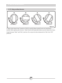
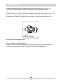
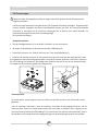
Changing Injectors:
Cooktop burners:
Shut off main gas.
Remove the burner cap and the upper burner (Figure 8).
Unscrew the injectors. For this, use a 7mm spanner (Figure 9).
Install the new injectors in accordance with the type of gas used, as shown on the technical data
table. Be careful to tighten straight the new injectors, because if you mount them sideways, you will
damage the thread of the rack and the rack will need to be changed (and it will not be in guarantee
extent).
Oven Injectors :
The oven burners are fitted by a single screw that is placed on the tip of the burner.
For the oven burner (below), open the oven door, remove the screws holding the lower sheet.
Open the compartment beneath the oven (pull-down door) to access the front screw located on
the burner (Figure 11). If the cooker has a sub-oven front , you must first dismantle the oven
door to gain access to the screws holding the sheet.
3. INSTALLATION
!
Figure 9
Injector
Spanner
Figure 8

3. INSTALLATION
13
Remove the burner screw, and move the burner diagonally to access the injector at the rear
bottom of the muffle oven (Figure 11).
Unscrew the injectors. For this, use a 7mm spanner. Install the new injectors in accordance with
the type of gas used, as shown on the technical data table. Be careful to tighten straight the new
injectors, because if you mount them sideways, you will damage the thread of the rack and the
rack will need to be changed (and it will not be in guarantee extent).
Adjusting the flame to minimum on the valve
The flame length at minimum position is adjusted with a flat screw located on the valve. For valves
with thermocouple, the screw is located on the side of the valve spindle (Figure 12).
To determine the min. position, ignite the burners one after another and set them at minimum
position. With the help of a small screwdriver fasten or loosen the by pass screw around 90
degrees. When the flame has a length of at least 4mm, the adjustment is correct. For control, make
sure that the flame does not die out when passing from the maximum position to the minimum
position. Create an artificial wind with your hand toward the flame to see if the flames are stable.
Figure 10 Figure 11
Screw
Injector
Figure 12
Bypass screw
Valve with thermocouple

3. INSTALLATION
14
For the oven burner, let it run at minimum position for 5 minutes. Open and close the oven
door 2-3 times to check the stability of the burner flame.
During the conversion from LPG to NG, the bypass screw must be unscrewed. When converting
from NG to LPG, the same screw must be tightened up. During this adjustment, make sure the
cooker is unplugged and the gas supply is open.
Changing the Gas Inlet:
Regularly check the expiry date of your cooker gas pipe. When the expiry date is reached, it is
necessary to change the hose.
These pipes are available on the market and must be consistent with current standards.
After changing the hose, you should check that there is no leakage by referring to the
information in the above paragraph: Connecting gas and checking leakage.
Figure 17
Figure 15
B
Screw(inside the hole)
Valve without flame failure device

4. USE OF YOUR PRODUCT
15
•
4.1 Using gas burners
Igniting the burners
The symbols of the levers on the control panel indicate the position of the burner.
Manual Ignition of the Gas Burners
If your cooker is not fitted with electrical ignition or in case there is a failure in the grid, follow
the procedures listed below:
For cooktop burners: To turn one of the burners, press and turn the valve lever concerned
counterclockwise until maximum position and immediately ignite a match or gas lighter near
the crown burner holes. Move the ignition source away as soon as you see a stable flame.
For cooktop burners with thermocouple: Cooktops fitted with safety thermocouple provide
security when the flame goes out accidentally. For this reason, during the manual ignition, press
and hold the valve lever until you see stable flames. If the flames remain unstable after releasing
the button, repeat the procedure. If the flame goes out, the thermocouple system will close off
the said gas valve towards the burner and will prevent any accumulation of unburned gas. You
must wait at least 90 seconds before re-igniting a gas burner after an automatic cut.
For the oven burner (fitted with thermocouple): All oven burners are fitted with safety
thermocouple and provide security when the flame goes out accidentally. To ignite the oven
burner, press and turn the oven valve lever counterclockwise until it reaches maximum position.
While pressing the lever, immediately ignite a match or gas lighter near the ignition hole located
on the left front of the burner. Once the burner is lit with a steady flame, withdraw the ignition
source at once and hold pressed for about 3 seconds. If the flames remain cut out after
releasing the knob, repeat the procedure. If the flame goes out, the thermocouple system will
shut off the gas inlet of the oven valve towards the burner and will prevent any accumulation of
unburned gas. If the oven burner does not ignite after you keep the burner knob pressed for at
least 30 seconds, open the oven door and do not attempt re-ignition until at least 90 seconds.
When oven flames go out accidentally, repeat the same procedure.

4. USE OF YOUR PRODUCT
16
MAX Position
Off Position
Intermediate
MIN Position
Figure 14
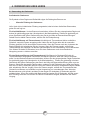
4.1.1
Cooktop valve levers have 3 positions: Off (0), max (big flame symbol) and min (small flame
symbol). After igniting the burner to "Max" position (as explained above), you can adjust the flame
length between "Max" and "Min" positions. Do not put the lever between the "Max” and “Off”
positions.
Using cooktop burners

4. USE OF YOUR PRODUCT
17
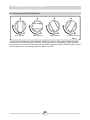
After the ignition, check the flames visually. If you see
yellow tip, lifted or unstable flames; turn the gas flow off,
and check the position of burner caps and crowns (fig.15).
Take note: these are very hot, let them cool to avoid burning
yourself. Be careful that no liquid flows inside the burners. If
the flames accidentally escape from the burner, close the
valves, ventilate the kitchen with fresh air, and wait at least 90
seconds before re-igniting.
To stop the cooking, turn the burner lever clockwise until the
mark on the lever is facing the point "0" (lever mark up).
Your cooktop is fitted with burners of different diameters.
The cheapest
way to use the gas is to reduce the flame to minimum position once you reach boiling point. It is
recommended to always cover your cooking pan.
Rapid Burner: 22-26cm
Semi-rapid burner 14-22cm
Auxiliary burner: 12-18cm
In order to obtain the most efficiency
from the cookers, pay attention to the sizes of saucepans that you put the on the cookers and
make sure that the saucepans have flat bases. Do not use saucepans with concave or convex
bottom to avoid wasting energy. Use proper-sized saucepans corresponding to the flame; if you
use containers smaller than those specified below, you will have wasted energy.
When not using your cooker for a long while, always close the gas inlet valve.
Use only flat pans.
Ensure that the base of the pan is dry before placing it on the burners.
WARNING:
•
•
Figure 16
!
Cap
Crown
Burner
Figure 15

•
•
The temperature of parts exposed to the flame can be very high when in use. So, it is imperative
to keep children and animals out of the reach of the burners during and after cooking.
After use, the cooktop remains hot for a long time. Do not touch it and do not place objects on
it.
4.1.2 Using the gas oven burner
Preheating
When you need to preheat the oven, we recommend you do so 10 minutes before placing a dish.
For recipes needing high temperatures, e.g. bread, pastries, scones, souffles, etc..., best results
are achieved if the oven is preheated first. For best results when cooking frozen or chilled food
always preheat the oven first.
Cooking
Your cooker has been delivered with wire shelf and oven tray. You may also use glass dishes,
cake pans, oven plates specially adapted to oven baking, which you may find on the market.
Make sure you follow the instructions given by the manufacturer on the possible use of the
dishes. If small sized containers are used, place them on the shelf such that they are precisely in
the middle of the wire. The following instructions should also be followed for all glazed dishes.
If food for cooking does not cover the entire surface of the cooktop, if it is food from the freezer,
the tray may undergo changes in shape due to high temperatures caused by cooking. The tray
will take back its original shape only when it has completely cooled after cooking. This is a
perfectly normal phenomenon caused by heat transfer.
If you use dishes and other glassware for cooking, do not expose directly to cold after taking
them out of the oven. Do not place on cold or wet surfaces. Place them on a dry kitchen towel or
on a trivet, and make sure they cool slowly, so as to prevent them from breaking.
•
•
•
•
• Be careful not to put the oven tray on the bottom of the oven because it may overheat and
damage the oven enamel.
18
4. USE OF YOUR PRODUCT
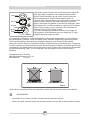
Figure 18
After igniting the oven burner as explained above, you may
adjust the temperature inside the oven, by positioning the
control in front of the signs on the control panel.
Do not operate the oven by placing the lever
between the "Off" position and the point indicating min
temperature (counterclockwise). Always use the oven
between the maximum and minimum positions. To stop the
cooking, turn the burner lever clockwise until the mark on the
lever is facing the point "0" (lever mark up).
If your oven
is fitted with an oven thermostat; refer to the temperature
table below to select temperature according to the food
cooked.
290
230
150
• It is important to ensure that the pan is centered correctly above the burners.

19
4. USE OF YOUR PRODUCT
•
•
•
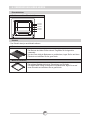
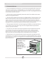
4.2 Accessories used in oven
The oven is supplied with accessories. You may also use accessories you purchase from the
market (but they must be heat and flame resistant). You can also use glass dishes, cake moulds,
special oven trays that are appropriate for use in oven. Pay attention to the manufacturer's user
instructions for accessories.
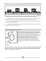
In case a small-sized dish is used, place the dish at the centre of the grid so that stands
correctly.
Do not place a glass baking pan in a cold environment immediately after cooking. Do not place
it on cold and wet surfaces either. Make sure it cools down gradually on a trivet or cloth,
otherwise it will break.
WARNING- Fit
the grid correctly
into any
correspondent
rack in the oven
cavity and push it
to the end.
Seite wird geladen ...
Seite wird geladen ...
Seite wird geladen ...
Seite wird geladen ...
Seite wird geladen ...
Seite wird geladen ...
Seite wird geladen ...
Seite wird geladen ...
Seite wird geladen ...
Seite wird geladen ...
Seite wird geladen ...
Seite wird geladen ...
Seite wird geladen ...
Seite wird geladen ...
Seite wird geladen ...
Seite wird geladen ...
Seite wird geladen ...
Seite wird geladen ...
Seite wird geladen ...
Seite wird geladen ...
Seite wird geladen ...
Seite wird geladen ...
Seite wird geladen ...
Seite wird geladen ...
Seite wird geladen ...
Seite wird geladen ...
Seite wird geladen ...
Seite wird geladen ...
Seite wird geladen ...
Seite wird geladen ...
Seite wird geladen ...
Seite wird geladen ...
Seite wird geladen ...
Seite wird geladen ...
Seite wird geladen ...
Seite wird geladen ...
Seite wird geladen ...
Seite wird geladen ...
Seite wird geladen ...
Seite wird geladen ...
Seite wird geladen ...
Seite wird geladen ...
Seite wird geladen ...
Seite wird geladen ...
Seite wird geladen ...
Seite wird geladen ...
Seite wird geladen ...
Seite wird geladen ...
Seite wird geladen ...
Seite wird geladen ...
Seite wird geladen ...
Seite wird geladen ...
Seite wird geladen ...
Seite wird geladen ...
Seite wird geladen ...
Seite wird geladen ...
Seite wird geladen ...
Seite wird geladen ...
Seite wird geladen ...
Seite wird geladen ...
Seite wird geladen ...
Seite wird geladen ...
Seite wird geladen ...
Seite wird geladen ...
Seite wird geladen ...
Seite wird geladen ...
Seite wird geladen ...
-
 1
1
-
 2
2
-
 3
3
-
 4
4
-
 5
5
-
 6
6
-
 7
7
-
 8
8
-
 9
9
-
 10
10
-
 11
11
-
 12
12
-
 13
13
-
 14
14
-
 15
15
-
 16
16
-
 17
17
-
 18
18
-
 19
19
-
 20
20
-
 21
21
-
 22
22
-
 23
23
-
 24
24
-
 25
25
-
 26
26
-
 27
27
-
 28
28
-
 29
29
-
 30
30
-
 31
31
-
 32
32
-
 33
33
-
 34
34
-
 35
35
-
 36
36
-
 37
37
-
 38
38
-
 39
39
-
 40
40
-
 41
41
-
 42
42
-
 43
43
-
 44
44
-
 45
45
-
 46
46
-
 47
47
-
 48
48
-
 49
49
-
 50
50
-
 51
51
-
 52
52
-
 53
53
-
 54
54
-
 55
55
-
 56
56
-
 57
57
-
 58
58
-
 59
59
-
 60
60
-
 61
61
-
 62
62
-
 63
63
-
 64
64
-
 65
65
-
 66
66
-
 67
67
-
 68
68
-
 69
69
-
 70
70
-
 71
71
-
 72
72
-
 73
73
-
 74
74
-
 75
75
-
 76
76
-
 77
77
-
 78
78
-
 79
79
-
 80
80
-
 81
81
-
 82
82
-
 83
83
-
 84
84
-
 85
85
-
 86
86
-
 87
87


Vestfrost FSHG 60 Usage And Installation Manual
- Typ
- Usage And Installation Manual
in anderen Sprachen
- English: Vestfrost FSHG 60
- Nederlands: Vestfrost FSHG 60
Andere Dokumente
-
Nordmende CSG52LPGWH Benutzerhandbuch
-
-
-
-
Beko CSG 52000 DW Benutzerhandbuch
-
-
Nordmende CTG51LPGBK Benutzerhandbuch
-
-
Nordmende HG62BL Kochfeld Benutzerhandbuch
-
Candy CCGG512SW/E Benutzerhandbuch