Parkside 327261 1904 Operating And Safety Instructions Manual
- Kategorie
- Elektrowerkzeuge
- Typ
- Operating And Safety Instructions Manual
Dieses Handbuch eignet sich auch für

IAN 327261_1904
CROSS CUT MITRE SAW PKS 1500 B3
CHAT
KAPP- UND GEHRUNGSSÄGE
Bedienungs- und Sicherheitshinweise
Originalbetriebsanleitung
DE
SKRACOVACIA A POKOSOVÁ PÍLA
Pokyny pre obsluhu a bezpečnostné pokyny
Preklad originálneho návodu na obsluhu
SK
BÜTÜZŐ ÉS GÉRVÁGÓ FŰRÉSZ
Kezelési és biztonsági útmutató
Az eredeti használati útmutató fordítása
HU
ČELILNA IN ZAJERALNA ŽAGA
Navodila za upravljanje in varnostna opozorila
Prevod originalnega navodila za uporabo
SI
CROSS CUT MITRE SAW
Operating and Safety Instructions
Translation of Original Operating Manual
GB
ZKRACOVACÍ A POKOSOVÁ PILA
Pokyny pro obsluhu a bezpečnostní pokyny
Překlad originálního provozního návodu
CZ
4

GB Operating and Safety Instructions Page 01
HU Kezelési és biztonsági útmutató Oldal 15
SI Navodila za upravljanje in varnostna opozorila Stran 30
CZ Pokyny pro obsluhu a bezpečnostní pokyny Strana 44
SK Pokyny pre obsluhu a bezpečnostné pokyny Strana 58
DE / AT / CH Bedienungs- und Sicherheitshinweise Seite 72
Klappen Sie vor dem Lesen die Seite mit den Abbildungen aus und machen Sie sich anschließend mit allen Funktionen des Gerätes vertraut.
DE AT CH
Pred branjem odprite stran s slikami in se nato seznanite z vsemi funkcijami naprave.
SI
Olvasás előtt kattintson az ábrát tartalmazó oldalra és végezetül ismerje meg a készülék mindegyik funkcióját.
HU
Před čtením si otevřete stranu s obrázky a potom se seznamte se všemi funkcemi přístroje.
CZ
Pred čítaním si odklopte stranu s obrázkami a potom sa oboznámte so všetkými funkciami prístroja.
SK
Before reading, unfold the page containing the illustrations and familiarise yourself with all functions of the device.
GB

1
4
14
15
11
3
5
6
7
8
9
10
12
13
16
17
1 2
2
18
14
19
20
22
23
21 15
4
17
3
18
14
20 21
24a
24
25
7
5
26
26a
A
25
6
13
38

8
27
28
7
811
33
34
12
36
35 36
6
8a
8b22
B
22
22a
10
29
30
5
6
9
32
23
4
13
37
31

1514
FFF F

1GB
Table of contents: Page:
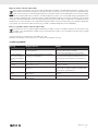
1. Explanation of the symbols on the equipment ..................................................................................................................................................2
2. Introduction ..........................................................................................................................................................................................................3
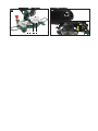
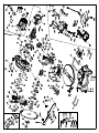
3. Device description (fig. 1-13) .............................................................................................................................................................................3
4. Scope of delivery ................................................................................................................................................................................................4
5. Proper use ............................................................................................................................................................................................................4
6. Safety information ............................................................................................................................................................................................... 4
7. Technical data ..................................................................................................................................................................................................... 8
8. Before starting the equipment ............................................................................................................................................................................8
9. Attachment and operation ..................................................................................................................................................................................9
10. Transport (fig. 13) .............................................................................................................................................................................................11
11. Maintenance .....................................................................................................................................................................................................11
12. Storage ..............................................................................................................................................................................................................11
13. Electrical connection .........................................................................................................................................................................................11
14. Disposal and recycling .....................................................................................................................................................................................12
15. Troubleshooting .................................................................................................................................................................................................13
16. Warranty certificate ..........................................................................................................................................................................................14
17. Declaration of conformity .................................................................................................................................................................................88

2 GB
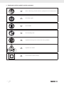
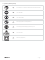
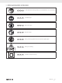
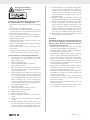
1. Explanation of the symbols on the equipment
GB
Before commissioning, read and observe the operating instructions and safety instructions!
GB
Wear safety goggles!
GB
Wear ear-muffs!
GB
Wear a breathing mask!
GB
Important! Risk of injury. Never reach into the running saw blade!
GB
Important! Laser radiation
GB
Protection Class II (double insulated)

3GB
2. Introduction
MANUFACTURER:
scheppach
Fabrikation von Holzbearbeitungsmaschinen GmbH
Günzburger Straße 69
D-89335 Ichenhausen
DEAR CUSTOMER,
we hope your new tool brings you much enjoyment and suc-
cess.
NOTE:
According to the applicable product liability laws, the manu-
facturer of the device does not assume liability for damages
to the product or damages caused by the product that occurs
due to:
• Improper handling,
• Non-compliance of the operating instructions,
• Repairs by third parties, not by authorized service techni-
cians,
• Installation and replacement of non-original spare parts,
• Application other than specified,
• A breakdown of the electrical system that occurs due to the
non-compliance of the electric regulations and VDE regula-
tions 0100, DIN 57113 / VDE0113.
We recommend:
Read through the complete text in the operating instructions be-
fore installing and commissioning the device.
The operating instructions are intended to help the user to be-
come familiar with the machine and take advantage of its ap-
plication possibilities in accordance with the recommendations.
The operating instructions contain important information on
how to operate the machine safely, professionally and econom-
ically, how to avoid danger, costly repairs, reduce downtimes
and how to increase reliability and service life of the machine.
In addition to the safety regulations in the operating instruc-
tions, you have to meet the applicable regulations that apply
for the operation of the machine in your country.
Keep the operating instructions package with the machine at
all times and store it in a plastic cover to protect it from dirt and
moisture. Read the instruction manual each time before operat-
ing the machine and carefully follow its information.
The machine can only be operated by persons who were in-
structed concerning the operation of the machine and who are
informed about the associated dangers. The minimum age re-
quirement must be complied with.
In addition to the safety instructions contained in this operating
manual and the specific regulations of your country, the techni-
cal rules generally accepted for the operation of machines of
the same type must be observed.
We accept no liability for damage or accidents which arise
due to non-observance of these instructions and the safety in-
formation.
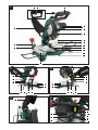
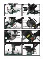
3. Device description (fig. 1-13)
1. ON/OFF switch
2. Lock switch
3. Handle
4. Machine head
5. Moving saw blade guard
6. Saw blade
7. Set screw for rotary table
8. Stop rail
8a. Movable stop rail
8b. Set screw
9. Fixed saw table
10. Table insert
11. Scale
12. Pointer
13. Rotary table
14. Set screw for workpiece support
15. Clamping device (workpiece clamp)
16. Set screw
17. Sawdust bag
18. Workpiece support
19. Set screw for clamping device
20. Set screw for drag guide
21. Support stand
22. Adjusting screw (45°)
23. Locking screw
24. Screw for cutting depth limiting
25. Stop for cutting depth limiting
26. Adjusting screw (90°)
27. Scale
28. Pointer
29. Flange screw
30. Outer flange
31. Guide bracket
32. Saw shaft lock
33. ON/OFF switch laser
34. Battery cover
35. Laser
36. Screw
37. Transport handle
38. Clamping handle
A.) 90° stop angle (not supplied)
B.) 45° stop angle (not supplied)
C.) Allen key, 6 mm
D.) Allen key, 3 mm
E.) Philips head screw (Laser)
F.) Philips head screw (table insert)

4 GB
4. Scope of delivery
• Cross cut mitre saw
• Dust bag
• Workpiece clamp
• Allen key 6 mm (C)
• Allen key 3 mm (D)
• 2 work piece supports
• Support stand
• 2 carbon brushes
• 2 batteries (AAA)
• Operating manual
5. Proper use
The cross cut mitre saw is designed to crosscut wood and plas-
tic respective of the machine’s size. The saw is not designed for
cutting firewood.
Warning! Do not use the saw to cut materials other than
those specified described in manual.
Warning! The supplied saw blade is only intended for the
sawing of wood! Do not use this blade for the sawing of fire-
wood!
The equipment is to be used only for its prescribed purpose.
Any other use is deemed to be a case of misuse. The user / op-
erator and not the manufacturer will be liable for any damage
or injuries of any kind caused as a result of this.
The equipment is to be operated only with suitable saw blades.
It is prohibited to use any type of cutting-off wheel.
To use the equipment properly you must also observe the safety
information, the assembly instructions and the operating instruc-
tions to be found in this manual.
All persons who use and service the equipment have to be
acquainted with this manual and must be informed about the
equipment’s potential hazards.
It is also imperative to observe the accident prevention regula-
tions in force in your area.
The same applies for the general rules of health and safety at
work.
The manufacturer will not be liable for any changes made to the
equipment nor for any damage resulting from such changes.
Even when the equipment is used as prescribed it is still im-
possible to eliminate certain residual risk factors. The following
hazards may arise in connection with the machine’s construc-
tion and design:
• Contact with the saw blade in the uncovered saw zone.
• Reaching into the running saw blade (cut injuries).
• Kick-back of workpieces and parts of workpieces.
• Saw blade fracturing.
• Catapulting of faulty carbide tips from the saw blade.
• Damage to hearing if ear-muffs are not used as necessary.
• Harmful emissions of wood dust when used in closed rooms.
Please note that our equipment has not been designed for use
in commercial, trade or industrial applications. Our warranty
will be voided if the equipment is used in commercial, trade or
industrial businesses or for equivalent purposes.
6. Safety information
General power tool safety information
m WARNING! Read all safety warnings, instruc-
tions, illustrations and technical data provided
with this power tool. Failure to follow the warnings and in-
structions may result in electric shock, fire and/or serious injury.
Save all warnings and instructions for future refer-
ence.
The term “power tool” in the warnings refers to your mains-
operated (corded) power tool or battery-operated (cordless)
power tool.
1) Work area safety
a) Keep work area clean and well lit. Cluttered or
dark areas invite accidents.
b) Do not operate power tools in explosive at-
mospheres, such as in the presence of flamma-
ble liquids, gases or dust. Power tools create sparks
which may ignite the dust or fumes.
c) Keep children and bystanders away while op-
erating a power tool. Distractions can cause you to
lose control.
2) Electrical safety
a) Power tool plugs must match the outlet. Never
modify the plug in any way. Do not use any
adapter plugs with earthed (grounded) pow-
er tools. Unmodified plugs and matching outlets will
reduce risk of electric shock.
b) Avoid body contact with earthed or grounded
surfaces, such as pipes, radiators, ranges and
refrigerators. There is an increased risk of electric
shock if your body is earthed or grounded.
c) Do not expose power tools to rain or wet con-
ditions. Water entering a power tool will increase the
risk of electric shock.
d) Do not abuse the cord. Never use the cord for
carrying, pulling or unplugging the power tool.
Keep cord away from heat, oil, sharp edges or
moving parts. Damaged or entangled cords increase
the risk of electric shock.
e) When operating a power tool outdoors, use
an extension cord suitable for outdoor use.
Use of a cord suitable for outdoor use reduces the risk of
electric shock.
f) If operating a power tool in a damp location
is unavoidable, use a residual current device
(RCD) protected supply. Use of an RCD reduces the
risk of electric shock.

5GB
3) Personal safety
a) Stay alert, watch what you are doing and use
common sense when operating a power tool.
Do not use a power tool while you are tired or
under the influence of drugs, alcohol or medi-
cation. A moment of inattention while operating power
tools may result in serious personal injury.
b) Use personal protective equipment. Always
wear eye protection. Protective equipment such as
a dust mask, non-skid safety shoes, hard hat or hearing
protection used for appropriate conditions will reduce
personal injuries.
c) Prevent unintentional starting. Ensure the
switch is in the off-position before connecting
to power source and/or battery pack, picking
up or carrying the tool.
Carrying power tools with your finger on the switch or
energising power tools that have the switch on invites ac-
cidents.
d) Remove any adjusting key or wrench before
turning the power tool on. A wrench or a key left
attached to a rotating part of the power tool may result in
personal injury.
e) Do not overreach. Keep proper footing and
balance at all times. This enables better control of the
power tool in unexpected situations.
f) Dress properly. Do not wear loose clothing or
jewellery. Keep your hair and clothing away
from moving parts. Loose clothes, jewellery or long
hair can be caught in moving parts.
g) If devices are provided for the connection of
dust extraction and collection facilities, en-
sure these are connected and properly used.
Use of dust collection can reduce dust-related hazards.
h) Do not let familiarity gained from frequent use
of tools allow you to become complacent and
ignore tool safety principles. A careless action can
cause severe injury within a fraction of a second.
4) Power tool use and care
a) Do not force the power tool. Use the correct
power tool for your application. The correct pow-
er tool will do the job better and safer at the rate for which
it was designed.
b) Do not use the power tool if the switch does
not turn it on and off. Any power tool that cannot
be controlled with the switch is dangerous and must be
repaired.
c) Disconnect the plug from the power source
and/or remove the battery pack, if detach-
able, from the power tool before making any
adjustments, changing accessories, or storing
power tools. Such preventive safety measures reduce
the risk of starting the power tool accidentally.
d) Store idle power tools out of the reach of chil-
dren and do not allow persons unfamiliar with
the power tool or these instructions to operate
the power tool. Power tools are dangerous in the
hands of untrained users.
e) Maintain power tools and accessories. Check
for misalignment or binding of moving parts,
breakage of parts and any other condition
that may affect the power tool’s operation. If
damaged, have the power tool repaired be-
fore use. Many accidents are caused by poorly main-
tained power tools.
f) Keep cutting tools sharp and clean. Properly main-
tained cutting tools with sharp cutting edges are less likely to
bind and are easier to control.
g) Use the power tool, accessories and tool bits
etc. in accordance with these instructions, tak-
ing into account the working conditions and
the work to be performed. Use of the power tool
for operations different from those intended could result in
a hazardous situation.
h) Keep handles and grasping surfaces dry,
clean and free from oil and grease. Slippery han-
dles and grasping surfaces do not allow for safe handling
and control of the tool in unexpected situations.
5) Service
a) Have your power tool serviced by a qualified
repair person using only identical replacement
parts. This will ensure that the safety of the power tool
is maintained.
Warning! This electric tool generates an electromagnetic
field during operation. This field can impair active or passive
medical implants under certain conditions. In order to prevent
the risk of serious or deadly injuries, we recommend that per-
sons with medical implants consult with their physician and the
manufacturer of the medical implant prior to operating the elec-
tric tool.
Safety instructions for mitre saws
a) Mitre saws are intended to cut wood or wood-
like products, they cannot be used with abra-
sive cut-off wheels for cutting ferrous material
such as bars, rods, studs, etc. Abrasive dust causes
moving parts such as the lower guard to jam. Sparks from
abrasive cutting will burn the lower guard, the kerf insert
and other plastic parts.
b) Use clamps to support the workpiece when-
ever possible. If supporting the workpiece by
hand, you must always keep your hand at least
100 mm from either side of the saw blade. Do
not use this saw to cut pieces that are too small
to be securely clamped or held by hand. If your
hand is placed too close to the saw blade, there is an in-
creased risk of injury from blade contact.
c) The workpiece must be stationary and
clamped or held against both the fence and
the table. Do not feed the workpiece into the
blade or cut “freehand” in any way. Unre-
strained or moving workpieces could be thrown at high
speeds, causing injury.

6 GB
d) Push the saw through the workpiece. Do not
pull the saw through the workpiece. To make
a cut, raise the saw head and pull it out over
the workpiece without cutting, start the motor,
press the saw head down and push the saw
through the workpiece. Cutting on the pull stroke is
likely to cause the saw blade to climb on top of the work-
piece and violently throw the blade assembly towards the
operator.
e) Never cross your hand over the intended line
of cutting either in front or behind the saw
blade. Supporting the workpiece “cross handed” i.e.
holding the workpiece to the right of the saw blade with
your left hand or vice versa is very dangerous.
f) Do not reach behind the fence with either
hand closer than 100 mm from either side of
the saw blade, to remove wood scraps, or for
any other reason while the blade is spinning.
The proximity of the spinning saw blade to your hand may
not be obvious and you may be seriously injured.
g) Inspect your workpiece before cutting. If the
workpiece is bowed or warped, clamp it with
the outside bowed face toward the fence. Al-
ways make certain that there is no gap be-
tween the workpiece, fence and table along
the line of the cut. Bent or warped workpieces can
twist or shift and may cause binding on the spinning saw
blade while cutting. There should be no nails or foreign
objects in the workpiece.
h) Do not use the saw until the table is clear of all
tools, wood scraps, etc., except for the work-
piece. Small debris or loose pieces of wood or other
objects that contact the revolving blade can be thrown
with high speed.
i) Cut only one workpiece at a time. Stacked multi-
ple workpieces cannot be adequately clamped or braced
and may bind on the blade or shift during cutting.
j) Ensure the mitre saw is mounted or placed on
a level, firm work surface before use. A level
and firm work surface reduces the risk of the mitre saw
becoming unstable.
k) Plan your work. Every time you change the
bevel or mitre angle setting, make sure the
adjustable fence is set correctly to support the
workpiece and will not interfere with the blade
or the guarding system. Without turning the tool
“ON” and with no workpiece on the table, move the saw
blade through a complete simulated cut to assure there will
be no interference or danger of cutting the fence.
l) Provide adequate support such as table exten-
sions, saw horses, etc. for a workpiece that is
wider or longer than the table top. Workpieces
longer or wider than the mitre saw table can tip if not se-
curely supported. If the cut-off piece or workpiece tips, it
can lift the lower guard or be thrown by the spinning blade.
m) Do not use another person as a substitute for
a table extension or as additional support. Un-
stable support for the workpiece can cause the blade to
bind or the workpiece to shift during the cutting operation
pulling you and the helper into the spinning blade.
n) The cut-off piece must not be jammed or
pressed by any means against the spinning
saw blade. If confined, i.e. using length stops, the cut-
off piece could get wedged against the blade and thrown
violently.
o) Always use a clamp or a fixture designed to
properly support round material such as rods
or tubing. Rods have a tendency to roll while being cut,
causing the blade to “bite” and pull the work with your
hand into the blade.
p) Let the blade reach full speed before contact-
ing the workpiece. This will reduce the risk of the
workpiece being thrown.
q) If the workpiece or blade becomes jammed,
turn the mitre saw off. Wait for all moving
parts to stop and disconnect the plug from
the power source and/or remove the battery
pack. Then work to free the jammed material.
Continued sawing with a jammed workpiece could cause
loss of control or damage to the mitre saw.
r) After finishing the cut, release the switch, hold
the saw head down and wait for the blade to
stop before removing the cut-off piece. Reach-
ing with your hand near the coasting blade is dangerous.
s) Hold the handle firmly when making an in-
complete cut or when releasing the switch be-
fore the saw head is completely in the down
position. The braking action of the saw may cause the
saw head to be suddenly pulled downward, causing a
risk of injury.
Safety Instructions for the handling of saw blades
1. Do not use damaged or deformed saw blades.
2. Do not use any insertion tools with cracks. Sort out
cracked insertion tools. Repairs are not permitted.
3. Do not use saw blades made of high speed steel.
4. Check the condition of the saw blades before using the
cross cut mitre saw.
5. Make sure that a suitable saw blade for the material to
be cut is selected.
6. Only use saw blades recommended by the manufacturer.
Saw blades designed to cut wood and similar materials
must comply with EN 847-1.
7. Do not use saw blades made of high-speed alloy steel
(HSS steel).
8. Only use saw blades for which the maximum permissible
speed is not lower than the maximum spindle speed of
the cross cut mitre saw and which are suitable for the
material to be cut.
9. Observe the saw blade direction of rotation.
10. Only insertion the saw blade if you have mastered their
use.
11. Observe the maximum speed. The maximum speed spec-
ified on the insertion tool may not be exceeded. If speci-
fied, observe the speed range.
12. Clean grease, oil and water off of the clamping surfaces.
13. Do not use any loose reducing rings or bushes for the
reducing of holes on saw blades.

7GB
14. Make sure that fixed reducer rings for securing the inser-
tion tool have the same diameter and have at least 1/3
of the cutting diameter.
15. Make sure that fixed reducer rings are parallel to each
other.
16. Handle insertion tool with caution. They are ideally
stored in the originally package or special containers.
Wear protective gloves in order to improve grip and to
further reduce the risk of injury.
17. Prior to the use of insertion tools, make sure that all pro-
tective devices are properly fastened.
18. Prior to use, make sure that the insertion tool meets the
technical requirements of this electric tool and is properly
fastened.
19. Only use the supplied saw blade for cutting wood, never
for the processing of metals.
20. Only use saw blade diameters in accordance with the
markings on the saw.
21. Use additional workpiece supports, if required for work-
piece stability.
22. Workpiece support extensions must always be secured
and used during work.
23. Replace table inserts when worn!
24. Avoid overheating of the saw teeth.
25. When sawing plastic, avoid melting of the plastic. Use
the appropriate saw blades for this purpose. Replace
damaged or worn saw blades immediately. When the
saw blade overheats, stop the machine. Allow the saw
blade to cool down before using the power tool again.
Attention: Laser radiation
Do not stare into the beam
Class 2 laser
Protect yourself and you environment from acci-
dents using suitable precautionary measures!
• Do not look directly into the laser beam with unprotected
eyes.
• Never look into the path of the beam.
• Never point the laser beam towards reflecting surfaces and
persons or animals. Even a laser beam with a low output can
cause damage to the eyes.
• Caution - methods other than those specified here can result
in dangerous radiation exposure.
• Never open the laser module. Unexpected exposure to the
beam can occur.
• If you do not use the device for a long time, the batteries
should be removed.
• The laser may not be replaced with a different type of laser.
• Repairs of the laser may only be carried out by the laser
manufacturer or an authorised representative.
Safety instructions for handling batteries
1. Always make sure that the batteries are inserted with the
correct polarity (+ and –), as indicated on the battery.
2. Do not short-circuit batteries.
3. Do not charge non-rechargeable batteries.
4. Do not overcharge batteries!
5. Do not mix old and new batteries or batteries of different
types or manufacturers! Replace an entire set of batteries
at the same time.
6. Immediately remove used batteries from the device and
dispose of them properly! Do not dispose batteries with
household waste. Defective or used batteries must be re-
cycled according to Directive 2006/66 / EC. Give back
batteries and / or the device has been offered to the col-
lective facilities. About disposal facilities you can inform
by your municipal or city government.
7. Do not allow batteries to heat up!
8. Do not weld or solder directly on batteries!
9. Do not dismantle batteries!
10. Do not allow batteries to deform!
11. Do not throw batteries into fire!
12. Keep batteries out of the reach of children.
13. Do not allow children to replace batteries without super-
vision!
14. Do not keep batteries near fire, ovens or other sources of
heat. Do not use batteries in direct sunlight or store them
in vehicles in hot weather.
15. Keep unused batteries in the original packaging and
keep them away from metal objects. Do not mix un-
packed batteries or toss them together! This can lead to
a short-circuit of the battery and thus damage, burns or
even the risk of fire.
16. Remove batteries from the equipment when it will not be
used for an extended period of time, unless it is for emer-
gencies!
17. NEVER handle batteries that have leaked without appro-
priate protection. If the leaked fluid comes into contact
with your skin, the skin in this area should be rinsed off
under running water immediately. Always prevent the
fluid from coming into contact with the eyes and mouth.
In the event of contact, please seek immediate medical
attention.
18. Clean the battery contacts and corresponding contacts in
the device prior to inserting the batteries.
Residual risks
The machine has been built according to the state
of the art and the recognised technical safety re-
quirements. However, individual residual risks can
arise during operation.
• Health hazard due to electrical power, with the use of im-
proper electrical connection cables.
• Furthermore, despite all precautions having been met, some
non-obvious residual risks may still remain.
• Residual risks can be minimised if the “Safety information“
and the “Proper use” are observed along with the whole of
the operating instructions.
• Do not load the machine unnecessarily: excessive pressure
when sawing will quickly damage the saw blade, which re-
sults in reduced output of the machine in the processing and
in cut precision.
• When cutting plastic material, please always use clamps:
the parts which should be cut must always be fixed between
the clamps.
• Avoid accidental starting of the machine: the operating but-
ton may not be pressed when inserting the plug in an outlet.

8 GB
• Use the tool that is recommended in this manual. In doing so,
your machine provides optimal performance.
• Hands may never enter the processing zone when the ma-
chine is in operation.
• Release the handle button and switch off the machine prior
to any operations.
7. Technical data
AC motor....................................................220 - 240 V
~
50 Hz
Power S1 .....................................................................1200 Watt
Operating mode ............................................ S6 25%* 1500W
Idle speed n
0
..............................................................5000 min
-1
Carbide saw blade ...............................ø 210 x ø 30 x 2,6 mm
Number of teeth .......................................................................48
Maximum saw blade tooth width ......................................3 mm
Swivel range ................................................... -45° / 0°/ +45°
Mitre cut ........................................................ 0° - 45° to the left
Saw width at 90° ................................................. 120 x 60 mm
Saw width at 45° ....................................................80 x 60 mm
Saw width at 2 x 45°
(double mitre cut) .....................................................80 x 35 mm
Protection class ...................................................................II /
Weight ......................................................................... ca. 7,6 kg
Laser class ...................................................................................2
Wavelength of laser ........................................................ 650 nm
Laser output .....................................................................< 1 mW
* S6, continuous operation periodic duty.
Identical duty cycles with a period at load followed by a period
at no load. Running time 10 minutes; duty cycle is 25% of the
running time.
The work piece must have a minimum height of 3
mm and a minimum width of 10 mm.
Make sure that the workpiece is always secured
with the clamping device.
Noise
Total noise values determined in accordance with EN 62841.
Sound pressure level L
pA
....................... 99,6 dB(A)
Uncertainty K
pA
...............................................3 dB
Sound power level L
WA
........................ 112,6 dB(A)
Uncertainty K
WA
..............................................3 dB
Wear hearing protection.
The effects of noise can cause a loss of hearing
The above-mentioned noise emission values were measured in
accordance with a standardised test procedure and can be
used to compare one power tool with another.
The above-mentioned noise emission values can also be used
for the preliminary assessment of exposure.
Warning:
• The noise emissions during the actual use of the power tool
may differ from the above-mentioned values depending on
the power tool being used, in particular on the type of work-
piece being processed.
• Try to keep emissions as low as possible, for example by
limiting your working time. In this regard, all the operational
cycle phases must be taken into consideration (such as the
times when the tool is switched off or running idle).
8. Before starting the equipment
• Open the packaging and remove the device carefully.
• Remove the packaging material as well as the packaging
and transport bracing (if available).
• Check that the delivery is complete.
• Check the device and accessory parts for transport damage.
• If possible, store the packaging until the warranty period has
expired.
ATTENTION
The device and packaging materials are not toys!
Children must not be allowed to play with plastic
bags, film and small parts! There is a risk of swal-
lowing and suffocation!
Always ensure that the machine is stable and can
stand securely, i. e. bolted down on a workbench.
• The equipment must be set up where it can stand securely.
Secure the machine on a workbench or a base frame with 4
screws (not included in delivery) using the holes on the fixed
saw table (9).
• All covers and safety devices have to be properly fitted be-
fore the equipment is switched on.
• It must be possible for the blade to run freely.
• When working with wood that has been processed before,
watch out for foreign bodies such as nails or screws, etc.
• Before you press the ON/OFF switch check that the saw
blade is fitted correctly. Moving parts must run smoothly.
• Before you connect the equipment to the power supply make
sure the data on the rating plate are identical to the mains
data.
8.1 Assembling the work piece clamping device
(fig. 2)
• Loosen the locking screw (19) and attach the work piece
clamping device (15) to the left or right of the fixed saw
bench.
• Afterwards, retighten the locking screws (19).
8.2 Assembling the work piece supports
(fig. 2 - 3)
• Loosen the locking screw (14) and guide the work piece
support through the specified hole on the side of the fixed
saw bench.
• Make sure that the work piece support (18) is also guided
through the two plates on the underneath.
• Afterwards, retighten the locking screw (14).
• Repeat this process on the other side.
8.3 Assembling the support stand (fig. 2 - 3)
• Loosen the locking screw (20) on the underneath of the saw
and guide the support stand (21) through the specified holes
on the back of the saw.
• Afterwards, retighten the locking screw (20).

9GB
8.4 Sawdust bag (fig. 4)
The saw is equipped with a debris bag (17) for sawdust and
chips.
Squeeze together the metal ring on the dust bag and attach it
to the outlet opening in the motor area.
The debris bag (17) can be emptied by means of a zipper at
the bottom.
Connection to an external dust extractor
• Connect the vacuum hose with the dust extraction spout.
• The industrial vacuum cleaner must be suitable for the mate-
rial being worked.
• When vacuuming dust that is especially detrimental to
health or carcinogenic, use a special vacuum cleaner.
8.5 Checking the moving saw blade guard safety
device (5)
The saw blade guard protects against accidental contact with
the saw blade and from chips flying around.
Check function
To do so, fold the saw downwards:
• The saw blade guard must provide free access to the saw
blade without touching other parts.
• When folding the saw upwards into the starting position, the
saw blade guard must cover the saw blade automatically.
9. Attachment and operation
9.1 Attaching the cross cut mitre saw (fig.1 - 3)
• Release the rotary table (13) by loosening the set screw (7).
• Using the handle (3), set the rotary table (13) to the desired
angle.
NOTE
The cross cut mitre saw can be pivoted left and right with the
rotary table. Exact angle adjustment is possible on the basis
of the scale. The angle can be precisely and quickly adjusted
from 0° to 45° with locking positions at 15°, 22.5° and
30°.
• Retighten the set screw (7) in order to secure the rotary table.
• Pressing the machine head (4) lightly downwards and re-
moving the locking bolt (25) from the motor bracket at the
same time disengages the saw from the lowest position.
• Swing the machine head (4) up.
• It is possible to secure the clamping device (15) to the left
or right on the stationary saw bench (9). Insert the clamping
device (15) in the hole on the rear side of the stop rail (8)
and secure it with the star grip screw (19).
• It is possible to tilt the machine head (4) a max. 45° to the
left by loosening the locking screw (23).
• Workpiece supports (18) must always be secured and used
during work.
9.2 Precision adjustment of the stop for crosscut
90° (fig. 5)
• No stop angle included.
• Lower the machine head (4) and secure it using the locking
bolt (25).
• Loosen the locking screw (23).
• Position the angle stop (A) between the saw blade (6) and
the rotary table (13).
• Loosen the lock nut (26a).
• Adjust the adjusting screw (26) until the angle between the
saw blade (6) and rotary table (13) is 90°.
• Re-tighten the lock nut (26a).
9.3 Crosscut 90° and turntable 0° (fig. 1/2/3/6)
Important. To make 90° crosscuts, the adjustable
stop rail (8a) must be fixed at the inner position.
• Open the set screw (8b) for the adjustable stop rail (8a) and
push the adjustable stop rail (8a) inwards.
• The adjustable stop rail (8a) must be fixed far enough in
front of the innermost position that the distance between the
stop rail (8a) and the saw blade (6) amounts to a maximum
of 8 mm.
• Before making a cut, check that the stop rail (8a) and the
saw blade (6) cannot collide.
• Secure the set screw (8b) again.
• Move the machine head (4) to its upper position.
• Place the piece of wood to be cut at the stop rail (8) and on
the turntable (13).
• Lock the material with the clamping devices (15) on the fixed
saw table (9) to prevent the material from moving during the
cutting operation. See section 9.13.
• Release the lock switch (2) and press the ON/OFF switch
(1) to start the motor.
• Use the handle (3) to move the machine head (4) steadily
and with light pressure downwards until the saw blade (6)
has completely cut through the work piece.
• When the cutting operation is completed, move the machine
head back to its upper (home) position and release the ON/
OFF button (1).
Attention! The machine executes an upward stroke auto-
matically due to the return spring, i.e. do not release the han-
dle (3) after completing the cut; instead allow the machine
head to move upwards slowly whilst applying light counter
pressure.
9.4 Crosscut 90° and turntable 0° - 45°
(fig. 1/2/3/6)
The cross cut mitre saw can be used to make crosscuts of 0°
-45° to the left and 0° -45° to the right in relation to the stop
rail.
Important. To make 90° crosscuts, the adjustable
stop rail (8a) must be fixed at the inner position.
• Open the set screw (8b) for the adjustable stop rail (8a) and
push the adjustable stop rail (8a) inwards.
• The adjustable stop rail (8a) must be fixed far enough in
front of the innermost position that the distance between the
stop rail (8a) and the saw blade (6) amounts to a maximum
of 8 mm.
• Before making a cut, check that the stop rail (8a) and the
saw blade (6) cannot collide.
• Secure the set screw (8b) again.
• Release the rotary table (13) by loosening the set screw (7).
• Using the handle (3), set the rotary table (13) to the desired
angle.
• Retighten the set screw (7) in order to secure the rotary table.
• Cut as described under section 9.3.

10 GB
9.5 Precision adjustment of the stop for mitre cut
45° (fig. 1/2/3/6/7/8)
• No stop angle included.
• Lower the machine head (4) and secure it using the locking
bolt (25).
• Fix the rotary table (13) in the 0° position.
Important. For mitre cuts, the adjustable stop rail (8a) must
be fixed at the inner position.
• Open the set screw (8b) for the moveable stop rail (8a) and
push the moveable stop rail (8a) outwards.
• The adjustable stop rail (8a) must be fixed far enough in
front of the innermost position that the distance between the
stop rail (8a) and the saw blade (6) amounts to a maximum
of 8 mm.
• Before making a cut, check that the stop rail (8a) and the
saw blade (6) cannot collide.
• Secure the set screw (8b) again.
• Loosen the locking screw (23) and use the handle (3) to
angle the machine head (4) 45° to the left.
• 45° - position angle stop (B) between the saw blade (6) and
rotary table (13).
• Loosen the locknut (22a) and adjust the adjustment screw
(22) until the angle between the saw blade (6) and the ro-
tary table (13) is precisely 45°.
• Re-tighten the locknut (22a).
• Subsequently check the position of the angle indicator. If
necessary, loosen the pointer (28) using a Philips screwdriv-
er, set to position 45° on the angle scale (27) and re-tighten
the retaining screw.
9.6 Mitre cut 0°- 45° and turntable 0° (fig. 1/2/3/6)
The cross cut mitre saw can be used to make mitre cuts of 0° -
45° in relation to the work face.
Important. For mitre cuts, the adjustable stop rail
(8a) must be fixed at the inner position.
• Open the set screw (8b) for the moveable stop rail (8a) and
push the moveable stop rail (8a) outwards.
• The adjustable stop rail (8a) must be fixed far enough in
front of the innermost position that the distance between the
stop rail (8a) and the saw blade (6) amounts to a maximum
of 8 mm.
• Before making a cut, check that the stop rail (8a) and the
saw blade (6) cannot collide.
• Secure the set screw (8b) again.
• Move the machine head (4) to the top position.
• Fix the rotary table (13) in the 0° position.
• Loosen the locking screw (23) and use the handle (3) to
angle the machine head (4) to the left, until the pointer (28)
indicates the desired angle measurement on the scale (27).
• Re-tighten the locking screw (23).
• Cut as described in section 9.3.
9.7 Mitre cut 0°- 45° and turntable 0°- 45°
(fig. 1/2/3/6)
The cross cut mitre saw can be used to make mitre cuts to the
left of 0°- 45° in relation to the work face and, at the same
time, 0° - 45° to the left or 0° - 45° to the right in relation to
the stop rail (double mitre cut).
Attention! For mitre cuts (inclined saw head), the
moveable stop rail (8a) must be fixed in the outer
position.
• Open the set screw (8b) for the moveable stop rail (8a) and
push the moveable stop rail (8a) outwards.
• The adjustable stop rail (8a) must be fixed far enough in
front of the innermost position that the distance between the
stop rail (8a) and the saw blade (6) amounts to a maximum
of 8 mm.
• Before making a cut, check that the stop rail (8a) and the
saw blade (6) cannot collide.
• Secure the set screw (8b) again.
• Move the machine head (4) to its upper position.
• Release the rotary table (13) by loosening the set screw (7).
• Using the handle (3), set the rotary table (13) to the desired
angle.
• Retighten the set screw (7) in order to secure the rotary table.
• Undo the locking screw (23).
• Use the handle (3) to tilt the machine head (4) to the left until
it coincides with the required angle value (in this connection
see also section 9.6).
• Re-tighten the locking screw (23).
• Cut as described under section 9.3.
9.8 Limiting the cutting depth (fig. 3)
• The cutting depth can be infinitely adjusted using the screw
(24). To do this loosen the locknut (24a) on the screw (24).
Turn the screw (24) in or out to set the required cutting depth.
Then re-tighten the locknut (24a) on the screw (24).
• Check the setting by completing a test cut.
9.9 Changing the saw blade (fig. 1/2/3/9/10)
Remove the power plug!
Important!
Wear safety gloves when changing the saw blade.
Risk of injury!
• Swing the machine head (4) upwards and secure with the
stop for cutting depth limiting (25).
• Fold the saw blade guard (5) upwards until the saw blade
guard (5) is above the flange screw (29).
• With one hand insert the Allen key (C) in the flange screw
(29).
• Hold the Allen key (C) and slowly close the saw blade guard
(5) until it touches the Allen key (C).
• Firmly press the saw shaft lock (32) and slowly rotate the
flange screw (29) in clockwise direction. The saw shaft lock
(32) engages after no more than one rotation.
• Now, using a little more force, slacken the flange screw (29)
in the clockwise direction.
• Turn the flange screw (29) right out and remove the outer
flange (30).
• Take the blade (6) off the inner flange and pull out down-
wards.
• Carefully clean the flange screw (29), outer flange (30) and
inner flange.
• Fit and fasten the new saw blade (6) in reverse order.
• Important! The cutting angle of the teeth, in other words the
direction of rotation of the saw blade (6) must coincide with
the direction of the arrow on the housing.
• Before continuing your work make sure that all safety de-
vices are in good working condition.

11GB
• Important! Every time that you change the saw blade (6),
check to see that it spins freely in the table insert (10) in both
perpendicular and 45° angle settings.
• Important! The work to change and align the saw blade (6)
must be carried out correctly.
9.10 Replacing laser batteries (fig. 11)
• Remove the laser battery cover (34). Remove the 2 batteries.
• Replace both batteries with the same or an equivalent type.
Make sure that they are inserted with the same polarity as
the used batteries.
• Close the battery cover.
9.11 Switch ON / switch OFF the laser (fig. 11)
To switch on: Move the ON/OFF (33) switch of the laser
(34) to the “1” position. A laser line is projected onto the mate-
rial you wish to process, providing an exact guide for the cut.
To switch off: Move the ON/OFF switch of the laser to the
“0” position.
9.12 Adjusting the laser (fig. 12)
If the laser (35) ceases to indicate the correct cutting line, you
can readjust the laser. To do so, open the screws (36) and set
the laser by moving sideways to that the laser beam strikes the
teeth of the saw blade (6).
9.13 Using the clamping handle (fig. 1/2)
• The height of the clamping device (15) can be adjusted via
the set screw (16).
• Lower the clamping device onto the workpiece.
• Tighten the set screw (16) firmly.
• Turn the clamping handle (38) clockwise to clamp the work-
piece.
• To release the workpiece, proceed in reverse order.
10. Transport (fig. 13)
• Tighten the set screw (7) in order to lock the rotary table (13)
• Press the machine head (4) downwards and secure with the
stop for cutting depth limiting (25). The saw is now locked in
the lower position.
• Carry the equipment by the transport handle (37).
• When reassembling the equipment proceed as described
under section 8 - 9.
11. Maintenance
m Warning! Prior to any adjustment, maintenance or service
work disconnect the mains power plug!
General maintenance measures
Wipe chips and dust off the machine from time to time using a
cloth. In order to extend the service life of the tool, oil the rotary
parts once monthly. Do not oil the motor.
When cleaning the plastic do not use corrosive products.
Cleaning the moving saw blade guard safety de-
vice (5)
Always check the saw blade guard for debris before using the
machine.
Remove old sawdust and splinters using a brush or similar tool.
Replacing the table insert (fig. 14)
Danger!
With a damaged table insert (10) there is a risk of small parts
getting stuck between table insert and saw blade, blocking the
saw blade. Immediately replace damaged table in-
serts!
1. Remove table insert screws (F).
2. Remove table insert.
3. Install new table insert.
4. Tighten the table insert screws (F).
Brush inspection
Check the carbon brushes after the first 50 operating hours
with a new machine, or when new brushes have been fitted.
After carrying out the first check, repeat the check every 10
operating hours.
If the carbon is worn to a length of 6 mm, or if the spring or
contact wire are burned or damaged, it is necessary to replace
both brushes. If the brushes are found to be usable following
removal, it is possible to reinstall them.
When servicing the carbon brushes, open the two latches coun-
terclockwise (as shown in figure 15). Then remove the carbon
brushes.
Replace the carbon brushes in the reverse order.
Service information
Please note that the following parts of this product are sub-
ject to normal or natural wear and that the following parts are
therefore also required for use as consumables.
Wear parts*: carbon brushes, saw blade, table inserts, saw-
dust bags
* Not necessarily included in the scope of delivery!
12. Storage
Store the device and its accessories in a dark, dry and frost-
proof place that is inaccessible to children. The optimum stor-
age temperature is between 5 and 30˚C.
Store the electrical tool in its original packaging.
Cover the electrical tool in order to protect it from dust and
moisture.
Store the operating manual with the electrical tool.
13. Electrical connection
The electrical motor installed is connected and
ready for operation. The connection complies with
the applicable VDE and DIN provisions. The cus-
tomer‘s mains connection as well as the extension
cable used must also comply with these regula-
tions.
Important information
In the event of an overloading the motor will switch itself off. Af-
ter a cool-down period (time varies) the motor can be switched
back on again.

12 GB
Damaged electrical connection cable.
The insulation on electrical connection cables is often dam-
aged.
This may have the following causes:
• Passage points, where connection cables are passed through
windows or doors.
• Kinks where the connection cable has been improperly fas-
tened or routed.
• Places where the connection cables have been cut due to
being driven over.
• Insulation damage due to being ripped out of the wall outlet.
• Cracks due to the insulation ageing.
Such damaged electrical connection cables must not be used
and are life-threatening due to the insulation damage.
Check the electrical connection cables for damage regularly.
Make sure that the connection cable does not hang on the
power network during the inspection.
Electrical connection cables must comply with the applicable
VDE and DIN provisions. Only use connection cables with the
marking „H05VV-F“.
The printing of the type designation on the connection cable
is mandatory.
Safety instructions for the replacement of dam-
aged or defective power supply cables
Type X:
If the power cord of this device is damaged, it must be replaced
by the manufacturer, their service department or a similarly
qualified person to avoid dangers.
AC motor:
The mains voltage must be 220 - 240 V∼.
• Extension cables up to 25 m long must have a cross-section
of 1.5 mm
2
.
• Connections and repairs of electrical equipment may only
be carried out by an electrician.
Please provide the following information in the event of any
enquiries:
• Type of current for the motor
• Machine data - type plate
14. Disposal and recycling
The equipment is supplied in packaging to prevent it from being
damaged in transit. The raw materials in this packaging can be
reused or recycled.
The equipment and its accessories are made of various types
of material, such as metal and plastic. Defective components
must be disposed of as special waste. Ask your dealer or your
local council.
The packaging is wholly composed of environment-
ally-friendly materials that can be disposed of at a
local recycling centre.
Contact your local refuse disposal authority for
more details of how to dispose of your worn-out
electrical devices.
Old devices must not be disposed of with house-
hold waste!
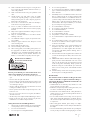
This symbol indicates that this product must not be dis-
posed of together with domestic waste in compliance
with the Directive (2012/19/EU) pertaining to waste
electrical and electronic equipment (WEEE). This prod-
uct must be disposed of at a designated collection point. This
can occur, for example, by handing it in at an authorised col-
lecting point for the recycling of waste electrical and electronic
equipment. Improper handling of waste equipment may have
negative consequences for the environment and human health
due to potentially hazardous substances that are often con-
tained in electrical and electronic equipment. By properly dis-
posing of this product, you are also contributing to the effective
use of natural resources. You can obtain information on collec-
tion points for waste equipment from your municipal administra-
tion, public waste disposal authority, an authorised body for
the disposal of waste electrical and electronic equipment or
your waste disposal company.
Batteries and rechargeable batteries do not be-
long in the household waste!
As the consumer you are required by law to bring all
batteries and rechargeable batteries, regardless
whether they contain harmful substances* or not, to a
collection point run by the local authority or to a retailer, so that
they can be disposed of in an environmentally friendly manner.
*labelled with: Cd = cadmium, Hg = mercury, Pb = lead
Remove the batteries from the laser before disposing of the ma-
chine and the batteries.

13GB
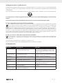
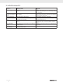
15. Troubleshooting
Fault Possible cause Remedy
Motor does not work Motor, cable or plug defective, fuses burnt Arrange for inspection of the machine by a specialist.
Never repair the motor yourself. Danger!
Check fuses and replace as necessary
The motor starts up slowly
and does not reach oper-
ating speed.
Voltage too low, coils damaged, capacitor burnt Contact the utility provider to check the voltage.
Arrange for inspection of the motor by a specialist. Ar-
range for replacement of the capacitor by a specialist
Motor makes excessive
noise
Coils damaged, motor defective Arrange for inspection of the motor by a specialist
The motor does not reach
its full power.
Circuits in the network are overloaded (lamps,
other motors, etc.)
Do not use any other equipment or motors on the same
circuit
Motor overheats easily. Overloading of the motor, insufficient cooling of
the motor
Avoid overloading the motor while cutting, remove dust
from the motor in order to ensure optimal cooling of the
motor
Saw cut is rough or wavy Saw blade dull, tooth shape not appropriate for
the material thickness
Re-sharpen saw blade and/or use suitable saw blade
Workpiece pulls away
and/or splinters
Excessive cutting pressure and/or saw blade not
suitable for use
Insert suitable saw blade

14 GB
16. Warranty certificate
Dear Customer,
All of our products undergo strict quality checks to ensure that they reach you in perfect condition. In the unlikely event that your device
develops a fault, please contact our service department at the address shown on this guarantee card. Of course, if you would prefer to
call us then we are also happy to offer our assistance under the service number printed below. Please note the following terms under which
guarantee claims can be made:
• These guarantee terms cover additional guarantee rights and do not affect your statutory warranty rights. We do not charge you for
this guarantee.
• Our guarantee only covers problems caused by material or manufacturing defects, and it is restricted to the rectification of these de-
fects or replacement of the device. Please note that our devices have not been designed for use in commercial, trade or industrial ap-
plications. Consequently, the guarantee is invalidated if the equipment is used in commercial, trade or industrial applications or for
other equivalent activities. The following are also excluded from our guarantee: compensation for transport damage, damage caused
by failure to comply with the installation/assembly instructions or damage caused by unprofessional installation, failure to comply with
the operating instructions (e.g. connection to the wrong mains voltage or current type), misuse or inappropriate use (such as overload-
ing of the device or use of non-approved tools or accessories), failure to comply with the maintenance and safety regulations, ingress
of foreign bodies into the device (e.g. sand, stones or dust), effects of force or external influences (e.g. damage caused by the device
being dropped) and normal wear resulting from proper operation of the device.
The guarantee is rendered null and void if any attempt is made to tamper with the device.
• The guarantee is valid for a period of 3 years starting from the purchase date of the device. Guarantee claims should be submitted
before the end of the guarantee period within two weeks of the defect being noticed. No guarantee claims will be accepted after the
end of the guarantee period. The original guarantee period remains applicable to the device even if repairs are carried out or parts
are replaced. In such cases, the work performed or parts fitted will not result in an extension of the guarantee period, and no new
guarantee will become active for the work performed or parts fitted. This also applies when an on-site service is used.
• In order to assert your guarantee claim, please contact the service partner shown below. If the complaint is within the guarantee pe-
riod, we will provide you with a return slip, with which you can return your defective device free of charge to us. It would help us if you
could describe the nature of the problem in as much detail as possible. If the defect is covered by our guarantee then your device will
either be repaired immediately and returned to you, or we will send you a new device.
Of course, we are also happy offer a chargeable repair service for any defects which are not covered by the scope of this guarantee or for
units which are no longer covered. To take advantage of this service, please send the device to our service address.
Service-Hotline (GB):
+800 4003 4003
(0,00 EUR/Min.)
Service-Email (GB):
service.GB@scheppach.com
Service Address (GB):
Forest Park & Garden
Coed Court, Taffsmead Road
Treforest, Ind. Estate, Pontypridd CF375SW
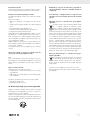
At www.lidl-service.com you can download this and many more manuals, product videos plus installation
software.
The QR code takes you directly to the Lidl service page (www.lidl-service.com) and you can open your oper-
ating manual by entering the article number (IAN) 327261_1904.

15HU
Tartalomjegyzék: Oldal:
1. A készüléken található szimbólumok magyarázata .......................................................................................................................................16
2. Bevezetés ...........................................................................................................................................................................................................17
3. A készülék leírása (1-13. ábra) .......................................................................................................................................................................17
4. Szállított elemek ................................................................................................................................................................................................18
5. Rendeltetésszerűi használatg ...........................................................................................................................................................................18
6. Biztonsági utasítások .........................................................................................................................................................................................18
7. Technikai adatok ...............................................................................................................................................................................................22
8. Az üzembe helyezés előtt ................................................................................................................................................................................23
9. Felépítés és kezelés ...........................................................................................................................................................................................23
10. Szállítás (13. ábra) ...........................................................................................................................................................................................25
11. Karbantartás ......................................................................................................................................................................................................26
12. Tárolás ...............................................................................................................................................................................................................26
13. Elektromos csatlakoztatás.................................................................................................................................................................................26
14. Megsemmisítés és újrahasznosítás ..................................................................................................................................................................27
15. Hibaelhárításe ...................................................................................................................................................................................................27
16. Jótállási tájékoztató...........................................................................................................................................................................................28
17. Megfelelőségi nyilatkozat ................................................................................................................................................................................88
Seite wird geladen ...
Seite wird geladen ...
Seite wird geladen ...
Seite wird geladen ...
Seite wird geladen ...
Seite wird geladen ...
Seite wird geladen ...
Seite wird geladen ...
Seite wird geladen ...
Seite wird geladen ...
Seite wird geladen ...
Seite wird geladen ...
Seite wird geladen ...
Seite wird geladen ...
Seite wird geladen ...
Seite wird geladen ...
Seite wird geladen ...
Seite wird geladen ...
Seite wird geladen ...
Seite wird geladen ...
Seite wird geladen ...
Seite wird geladen ...
Seite wird geladen ...
Seite wird geladen ...
Seite wird geladen ...
Seite wird geladen ...
Seite wird geladen ...
Seite wird geladen ...
Seite wird geladen ...
Seite wird geladen ...
Seite wird geladen ...
Seite wird geladen ...
Seite wird geladen ...
Seite wird geladen ...
Seite wird geladen ...
Seite wird geladen ...
Seite wird geladen ...
Seite wird geladen ...
Seite wird geladen ...
Seite wird geladen ...
Seite wird geladen ...
Seite wird geladen ...
Seite wird geladen ...
Seite wird geladen ...
Seite wird geladen ...
Seite wird geladen ...
Seite wird geladen ...
Seite wird geladen ...
Seite wird geladen ...
Seite wird geladen ...
Seite wird geladen ...
Seite wird geladen ...
Seite wird geladen ...
Seite wird geladen ...
Seite wird geladen ...
Seite wird geladen ...
Seite wird geladen ...
Seite wird geladen ...
Seite wird geladen ...
Seite wird geladen ...
Seite wird geladen ...
Seite wird geladen ...
Seite wird geladen ...
Seite wird geladen ...
Seite wird geladen ...
Seite wird geladen ...
Seite wird geladen ...
Seite wird geladen ...
Seite wird geladen ...
Seite wird geladen ...
Seite wird geladen ...
Seite wird geladen ...
Seite wird geladen ...
Seite wird geladen ...
Seite wird geladen ...
Seite wird geladen ...
-
 1
1
-
 2
2
-
 3
3
-
 4
4
-
 5
5
-
 6
6
-
 7
7
-
 8
8
-
 9
9
-
 10
10
-
 11
11
-
 12
12
-
 13
13
-
 14
14
-
 15
15
-
 16
16
-
 17
17
-
 18
18
-
 19
19
-
 20
20
-
 21
21
-
 22
22
-
 23
23
-
 24
24
-
 25
25
-
 26
26
-
 27
27
-
 28
28
-
 29
29
-
 30
30
-
 31
31
-
 32
32
-
 33
33
-
 34
34
-
 35
35
-
 36
36
-
 37
37
-
 38
38
-
 39
39
-
 40
40
-
 41
41
-
 42
42
-
 43
43
-
 44
44
-
 45
45
-
 46
46
-
 47
47
-
 48
48
-
 49
49
-
 50
50
-
 51
51
-
 52
52
-
 53
53
-
 54
54
-
 55
55
-
 56
56
-
 57
57
-
 58
58
-
 59
59
-
 60
60
-
 61
61
-
 62
62
-
 63
63
-
 64
64
-
 65
65
-
 66
66
-
 67
67
-
 68
68
-
 69
69
-
 70
70
-
 71
71
-
 72
72
-
 73
73
-
 74
74
-
 75
75
-
 76
76
-
 77
77
-
 78
78
-
 79
79
-
 80
80
-
 81
81
-
 82
82
-
 83
83
-
 84
84
-
 85
85
-
 86
86
-
 87
87
-
 88
88
-
 89
89
-
 90
90
-
 91
91
-
 92
92
-
 93
93
-
 94
94
-
 95
95
-
 96
96


Parkside 327261 1904 Operating And Safety Instructions Manual
- Kategorie
- Elektrowerkzeuge
- Typ
- Operating And Safety Instructions Manual
- Dieses Handbuch eignet sich auch für
in anderen Sprachen
- slovenčina: Parkside 327261 1904
Verwandte Artikel
-
Parkside PKS 1500 A2 Operating And Safety Instructions Manual
-
Lidl PZKS 1500 B2 Bedienungsanleitung
-
Parkside PZKS 2000 A1 Operating And Safety Instructions Manual
-
-
-
-
-
-
-
Andere Dokumente
-
Stanley FME720 Benutzerhandbuch
-
Scheppach HM90SL Benutzerhandbuch
-
Metabo KGS 255 Plus Operating Instructions Manual
-
-
-
Peugeot Energysaw-305DB Operating Instructions Manual
-
Metabo KGT 305 M Bedienungsanleitung
-
Matrix 210.200.356 Operational Manual
-
Metabo KS 305 M Bedienungsanleitung
-