
Level measurement
CleverLevel® LBFS
Point level detection
EN Operating Instructions 3
DE Betriebsanleitung 17
FR Manuel de mise en service 31

Operating Instructions
Level measurement
CleverLevel® LBFS
Point level detection
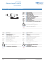
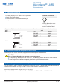
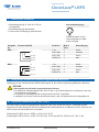
Type plate / Typenschild / Plaque d‘identication
Type Type of sensor
Matr. Material number
In Input voltage and
power consumption
Out PNP or NPN, customer-specic
Maximum external load
Tamb Ambient temperature
S/N Serial number
Date Date of manufacture
Do not dispose of in household waste
Conformity with EU directives
Approvals, type-specic
Type Sensortyp
Matr. Materialnummer
In Eingangsspannung und
Stromverbrauch
Out PNP oder NPN, kundenspezisch
Maximale externe Last
Tamb Umgebungstemperatur
S/N Seriennummer
Date Herstellungsdatum
Nicht im Hausmüll entsorgen
Konformität mit EU-Richtlinien
Zulassungen, typspezifisch
Type Type de capteur
Matr. Réf. mat.
In Tension d’entrée et consommation
électrique
Out PNP ou NPN, en fonction du client
Charge externe maximale
Tamb Température ambiante
S/N Numéro de série
Date Date de fabrication
Ne pas jeter avec les ordures
ménagères
Conformité avec les directives
européennes
Autorisations, selon le type
LBFS-00100.0
2 / 48 www.baumer.com

Operating Instructions
Level measurement
CleverLevel® LBFS
Point level detection
Table of contents
Table of contents .................................................. 3
1. Safety .......................................................... 3
2. Construction and function ........................... 3
3. Symbols in warning signs ............................ 4
4. Transport and storage ................................. 4
5. Assembly ..................................................... 4
6. Permissions ................................................. 8
7. Electrical connection ................................... 9
8. Electrical connection in explosion hazard
areas ........................................................... 9
9. Conguration ..............................................12
10. Operation ...................................................12
11. Cleaning, maintenance and repair..............13
12. Disposal .....................................................13
13. Accessories ................................................13
14. Technical data ............................................13
15. Factory settings and user settings ............ 16
1. Safety
Intended use
The sensor must be used solely for the level
detection of liquids and solids with a dielectric
constant of at least 1.5.
The sensor must only be used for media against
which the housing material and sensor tip are
resistant.
Staff qualication
Only use staff who are trained for the activities
described. This applies in particular to assembly,
installation and explosion protection. Make sure
that the staff have read and understood these
instructions.
Technical condition
Use the sensor only when in perfect technical
condition. Only use Baumer accessories.
Baumer will accept no liability for other
manufacturers’ accessories.
Risk of burns from hot media
During operation the sensor housing may warm
up to over 50 °C. When working with hot media
provide protection against burns.
Explosion hazard areas
Ensure that safety requirements are complied with.
Do not use equipment that would be exposed to
hard impacts.
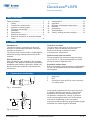
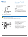
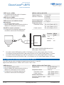
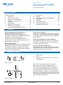
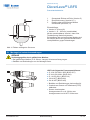
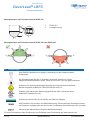
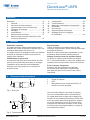
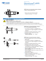
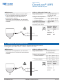
2. Construction and function
1 2 3
Fig. 1. Construction
fL
C
µC
Fig. 2. Function
1 Sensor tip
2 LED
3 Connection using a M12-A 4-pin connector,
or a cable outlet
An electrode integrated into the sensor tip forms
a capacitor with the environment. The medium
determines the capacity value depending on
its dielectric constant (DC values). A resonant
circuit occurs together with a coil in the sensor
electronics. Depending on the resonance
frequency measured and the programmable trigger
threshold, the switch signal is activated.
www.baumer.com 3 / 48

Operating Instructions
Level measurement
CleverLevel® LBFS
Point level detection
3. Symbols in warning signs
Symbol Warning term Explanation
DANGER In situations which cause death or serious injuries.
WARNING In situations which can cause death or serious injuries.
CAUTION In situations which can cause light or medium injuries.
ATTENTION For material damage
4. Transport and storage
fCheck packaging and sensor for damage.
fIn the event of damage: Do not use sensor.
fStore sensor where it will be secure against
shock.
Storage temperature: -40...+85 °C
Relative humidity: < 98 %
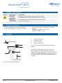
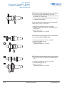
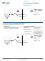
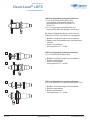
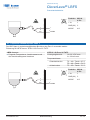
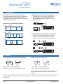
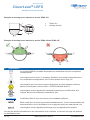
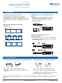
5. Assembly
2
4
1
3
4
4
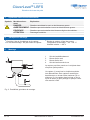
Fig. 3. General mounting options
1 Overll protection
2 Limit level, max.
3 Limit level, min.
4 Run-dry protection
The sensor can be mounted on any point in the
vessel.
A sensor mounted at the top of the vessel (1)
ensures against overlling. Sensors attached
further down detect a maximum (2) or minimum (3)
limit level. A sensor attached at the bottom or on
the outfeed pipe (4) can protect a pump against dry
running.
4 / 48 www.baumer.com

Operating Instructions
Level measurement
CleverLevel® LBFS
Point level detection
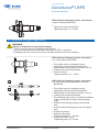
1
2
3
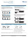
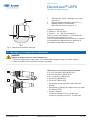
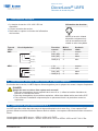
Fig. 4. Mounting of extended sensors
1 Limit level: Mounting with a tube (version 5)
2 Overll protection (Type K, L)
3 Pasty or powdered media
limit level (version K, L)
Dip length:
Type K: 82 mm (xed)
Type L: 15…228 mm (adjustable)
The adjustable version L allows bridging across
tank insulation.
In pasty or powdered media, the greater dip depth
renders the sensor less susceptible to caking.
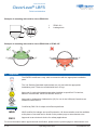
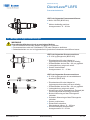
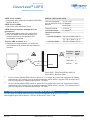
5.1 Installation for industrial applications
DANGER
Risk of injury from hazardous medium
fWear protective equipment for hazardous media (such as acids, alkalis).
fEmpty vessel and pipelines before mounting.
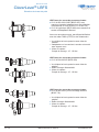
PTFE
1
2
LBFS with the following process connections:
G 1/2 A ISO 228-1 BSC (BCID G07)
G 3/4 A ISO 228-1 (BCID G10)
G 1 A ISO 228-1 (BCID G11)
1/2-14 NPT (BCID N02)
3/4-14 NPT (BCID N03)
9Vessel and pipelines are free of media.
fSeal thread on sensor with Teon tape (PTFE).
fScrew in sensor.
Tightening torque G xx A: 30 Nm max.
Tightening torque xx-14 NPT: 20 Nm max.
www.baumer.com 5 / 48

Operating Instructions
Level measurement
CleverLevel® LBFS
Point level detection
LBFS with the following process connections:
G 1/2 A ISO 228-1 BSC (BCID G07) with
industrial weld-in sleeve for universal use, Ø 30 x
26 (ZPW1-711, ZPW1-721)
G 1/2 A hygienic (BCID A03) with weld-in sleeve
or adapter from Baumer
For these process connections, do not seal with
Teon tape (PTFE) or elastomer.
9Vessel and pipelines are free of media.
9Adapter or weld-in sleeve are mounted free of
dead space.
fScrew in sensor.
Tightening torque: 15…20 Nm
1
2
LBFS with the following process connections:
G 1/2 A DIN 3852-E (BCID G51)
9Vessel and pipelines are free of media.
fPush the sealing ring on.
fScrew in sensor.
Tightening torque: 15…20 Nm
1
2
LBFS with the following process connections:
G 1/2 A ISO 228-1 for internal installation (BCID
T10)
9Vessel and pipelines are free of media.
fPush the sealing ring on.
fScrew in sensor.
Tightening torque: 15…20 Nm
6 / 48 www.baumer.com

Operating Instructions
Level measurement
CleverLevel® LBFS
Point level detection
LBFS with the following process connections:
M18x1 ISO 965 (BCID M11)
fTighten the nuts on both sides.
Tightening torque: 15…20 Nm
5.2 Installation for hygiene applications
WARNING
Danger to health from contaminated medium
fOnly use weld-in sleeves or adapters from Baumer.
fDo not seal process connections with Teon tape (PTFE) or elastomer.
fWelding work must only be carried out by welders trained in the area of hygiene.
LBFS with the following process connection:
G 1/2 A hygienic (BCID A03)
9The weld-in sleeve or adapter must be
hygienically mounted and internally ush.
9Weld seams are smoothed out to Ra < 0.8 µm.
9Leakage hole points downwards.
fScrew in sensor.
Tightening torque: 10… 15 Nm
1
2
LBFS with the following process connection:
G 1/2 A hygienic with adjustable connection
(BCID A03)
9The weld-in sleeve or adapter must be
hygienically mounted and internally ush.
9Weld seams are smoothed out to Ra < 0.8 µm.
9Leakage hole points downwards.
9The clamping rings must be in faultless condition
(if they are deformed, replace both clamping
rings).
fPush the wide clamping ring on to the guide
tube.
fPush the narrow clamping ring on to the guide
tube.
fPosition the sensor.
fAdjust the dip depth.
Projecting length: 15…228 mm
fTighten the screw-in pin.
Tightening torque: 22…25 Nm
www.baumer.com 7 / 48

Operating Instructions
Level measurement
CleverLevel® LBFS
Point level detection
Example of mounting with weld-in sleeve ZPW3-321
1
1
12
1
2
ZPW3-321
Leakage hole
Example of mounting with weld-in sleeve ZPW3-326 or ZPW3-327
170°
5°5° 5°5°
190°
6. Approvals
Approved as an electronic device for railway applications.
For more information about approvals and certication, please see the product page on www.baumer.com.
8 / 48 www.baumer.com
The EHEDG certificate is only valid in connection with the appropriate installation
parts.
The 3-A Sanitary Standard requirements are only met with the appropriate
installation parts. These are marked with the 3-A logo.
Approved for explosion hazard areas when installed as specied. For barriers,
Baumer recommends: PROFSI3-B25100-ALG-LS.
Approved by Underwriter Laboratories (UL) for use in the USA and Canada as an
industrial control device.
Certied by DNV GL for ships and offshore platforms.
WHG certified for leakage and overfill protection. All documentation must be available
at the place of use and can be found on the product page on www.baumer.com
WHG

Operating Instructions
Level measurement
CleverLevel® LBFS
Point level detection
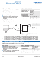
7. Electrical connection
9A voltage supply of 12 V to 30 V DC is provided.
fSwitch off supply voltage.
fConnect sensor in accordance with the pin
assignment.
Terminal assignment
12
43
Housing dimensions avail-
able only for a plug con-
nector in stainless steel
Output
type
Equivalent circuit Function M12-A
4-pin
Cable outlet
PNP
SW1 (NC)
GND(0V)
+Vs
SW1 (NO)
+ Vs 1brown
SW1 (NO) 4black
SW1 (NC) 2white
GND (0 V) 3 blue
NPN
SW1 (NC)
GND(0V)
+Vs
SW1 (NO)
+ Vs 1brown
SW1 (NO) 4black
SW1 (NC) 2white
GND (0 V) 3 blue
8. Electrical connection in explosion hazard areas
Depending on the variant, the LBFS is approved for most explosion hazard areas.
DANGER
Risk of fatal accident due to a wrongly connected sensor
fIn explosive gas atmospheres of zone 0 or 1, use Baumer isolation barriers or Zener barriers.
fIn explosive dust atmospheres, use insulated cable to IP67.
fAllow only persons trained in explosion protection to perform the installation.
8.1 Explosive gas atmospheres zone 0 and 1
The LBFS can be used in explosion hazard areas of zone 0 or zone 1. Sensors with PNP can use Baumer
isolation barriers which are easy to install. Sensors with NPN must use Zener barriers.
Approval for LBFS-1xxxx.x: ATEX II 1G Ex ia IIC T4/T5
Approval for LBFS-4xxxx.x: ATEX II 1G Ex ia IIC T4/T5 and ATEX II 1D Ex ta IIIC T100 °C Da
www.baumer.com 9 / 48

Operating Instructions
Level measurement
CleverLevel® LBFS
Point level detection
LBFS-1xxx1.x (PNP):
fUse PROFSI3-B25100-ALG-LS isolation
barriers for the connection.
LBFS-1xxx2.x (NPN):
fUse Zener barriers for the connection.
LBFS-4xxxx.x and additional dust
atmospheres:
fUse insulated cable to IP67.
fSecure cables with external strain relief at a
distance 5 centimeters from the sensor.
All LBFS in zone 0 and zone 1
fComply with the following temperatures,
connection values and circuit diagram.
ATEX II 1 G Ex ia IIC T4/T5
Highest values for
selection of barriers
Ui: 30 V DC
Ii: 100 mA
Pi: 0,75 W
Internal capacitance: Ci: 43 nF 1)
Internal inductance: Li: 10 µH 2)
Temperature class
Standard version T4: –40 < Tamb < 85 °C
T5: –40 < Tamb < 74 °C,
Cable version T5: –25 < Tamb < 70 °C
1
3
4/2
+
-
NO/NC
Function M12-A
4-pin
+ Vs 1
GND (0V) 3
NO/NC 4/2
PNP output: PROFSI3-B25100-ALG-LS
NPN output: Zener barrier
1) For cable version LBFS-x2xxx.x add 0.17 nF/meter to Ci for cable lengths above 5 meter.
For hanging version LBFS-xx52x.x add 0.20 nF/meter to Ci for cable lengths above 1.5 meter.
2) For cable version LBFS-x2xxx.x add 0.27 µH/meter to Li for cable lengths above 5 meter.
For hanging version LBFS-xx52x.x add 1.13 µH/meter to Li for cable lengths above 1.5 meter.
8.2 Explosive dust atmospheres zones 20, 21 and 22
The LBFS can be used in explosion hazard areas of zone 20, 21 and 22.
Approval for LBFS-2xxxx.x: ATEX II 1D Ex ta IIIC T100 °C Da
LBFS-2xxxx.x: ATEX II 1 D Ex ta IIIC T100 °C Da
fUse insulated cable to IP67.
fSecure cables with external strain relief at a
distance 5 centimeters from the sensor.
fComply with the following temperatures,
connection values and circuit diagram.
Supply range Un: 30 V DC max.
In: 100 mA max.
Temperature class T100 °C:
Standard version –40 < Tamb < 85 °C
Cable version –25 < Tamb < 70 °C
Surface temperature 100 °C max.
Protection class for cable
accessories
IP67
10 / 48 www.baumer.com

Operating Instructions
Level measurement
CleverLevel® LBFS
Point level detection
1
3
4/2
+
-
NO/NC
Function M12-A
4 pin
+ Vs 1
GND (0V) 3
NO/NC 4/2
8.3 Explosive gas atmospheres zone 2
The LBFS can be used in explosion hazard areas of zone 2.
Approval for LBFS-3xxxx.x: ATEX II 3G Ex ec IIC T4/T5
LBFS-3xxxx.x: ATEX II 3 G Ex ec IIC T4/T5
fComply with the following temperatures,
connection values and circuit diagram
Supply range Un: 30 V DC max.
In: 100 mA max.
Temperature class
Standard version T4: –40 < Tamb < 85 °C
T5: –40 < Tamb < 74 °C
Cable version T5: –25 < Tamb < 70 °C
1
3
4/2
+
-
NO/NC
Function M12-A
4 pin
+ Vs 1
GND (0V) 3
NO/NC 4/2
www.baumer.com 11 / 48

Operating Instructions
Level measurement
CleverLevel® LBFS
Point level detection
9. Conguration
The sensor can be congured with the
FlexProgrammer. This allows switching points
and damping values to be selected as required. In
addition pulse width modulation can be specied
for the signal.
Examples for pulse width modulation
U 10%
t
U 50%
t
U 75%
t
Conguring with FlexProgrammer and PC
fConnect FlexProgrammer to sensor.
fConnect FlexProgrammer to PC and set
parameters (see FlexProgrammer instructions).
Copying conguration with FlexProgrammer
fCopy the conguration of one sensor to
another sensor using FlexProgrammer (see
FlexProgrammer instructions)
1
2
10. Operation
Standard operation with factory settings LED indication for “Power-On”
BU
BU = blue: Switched output, active
LED does not light up: Switched output, inactive
BU GN
BU = blue: Switched output, active
GN = green: Switched output, inactive
A green LED can be activated indicating „Power-
On“ by using the FlexProgrammer.
Application-specic settings: see chapter “15. Factory settings and user settings” on page 16.
12 / 48 www.baumer.com

Operating Instructions
Level measurement
CleverLevel® LBFS
Point level detection
11. Cleaning, maintenance and repair
Cleaning
fClean, disinfect or sterilize sensor as needed
(CIP/SIP).
Maintenance
Regular maintenance is not required.
Repair
Do not repair the sensor yourself.
fSend damaged sensor to Baumer.
12. Disposal
fDo not dispose of in household waste.
fSeparate materials and dispose of in
compliance with nationally applicable
regulations.
13. Accessories
For adapter and other accessories see www.baumer.com.
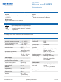
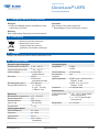
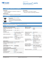
14. Technical data
Environmental conditions Output signal
Operating temperature range – 40…+85 °C Output type PNP
NPN
Storage temperature range –40…+85 °C
Ambient humidity < 98 % RH,
condensing
Current load 20 mA max.
Short circuit
protection
yes
Protection class IP67
IP69K (with
appropriate cable) Voltage drop PNP: (+Vs –1.5 V) ± 0.5 V,
Rload = 10 kΩ
NPN: (+1.5 V) ± 0.5 V,
Rload = 10 kΩ
Oscillations (sinusoidal)
(EN 60068-2-6)
1.6 mm p-p
(2…25 Hz),
4 g (25…100 Hz),
1 octave / min. Leakage current ± 100 μA max.
Switching logic Normally open (NO),
active low
Normally closed (NC),
high enabled
Power supply
Voltage supply range 12…30 V DC
Reverse polarity protection yes
Current consumption
(without load)
25 mA typ.,
50 mA max.
Cable version
Operating tempera-
ture range
–25…+70 °C (if cable is not
moved)
–5…+70 °C (if cable is
moved)
Power-up time < 2 s
Features
Repeatability ± 1 mm
Hysteresis ± 1 mm Bending radius min. r ≥ 10 mm
Response time 0.1 s
Damping 0.0…10.0 s
(congurable)
www.baumer.com 13 / 48

Operating Instructions
Level measurement
CleverLevel® LBFS
Point level detection
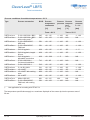
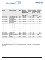
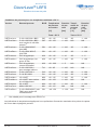
Process conditions for ambient temperatures < 50 °C
Type Process connection BCID Process
temperature
continuous
[°C]
Process
pressure
[bar]
Process
tempera-
ture
t < 1 h
[°C]
Process
pressure
t < 1 h
[bar]
Tamb < 50 °C Tamb < 50 °C
LBFS-xx1xx.x G 1/2 A ISO 228-1 BSC G07 - 40…115 -1…10 0 135 -1…10 0
LBFS-xxGxx.x G 1/2 A ISO 228-1 BSC
with cooling neck 1)
G07 - 40…15 0 -1…100 N/A N/A
LBFS-xxAxx.x G 1/2 A DIN 3852-E,
NBR seal
G51 - 40…115 -1…10 0 135 -1…10 0
LBFS-xxBxx.x G 1/2 A DIN 3852-E,
FKM seal
G51 - 40…115 -1…10 0 135 -1…10 0
LBFS-xx4xx.x G1/2 A hygienic A03 - 40…115 -1…10 135 -1…5
LBFS-xxKxx.x G1/2 A hygienic, length
82 mm
A03 - 40…115 -1…10 0 135 -1…100
LBFS-xxLx.x G1/2 A hygienic,
adjustable connection
A03 -40…200 -1…5 N/A N/A
LBFS-xx5xx.x G 1/2 A ISO 228-1
for internal installation
T10 -40…85 -1…10 0 N/A N/A
LBFS-xx2xx.x G 3/4 A ISO 228-1 G10 - 40…115 -1…10 0 135 -1…10 0
LBFS-xx3xx.x G 1 A ISO 228-1 G11 - 40…115 -1…10 0 135 -1…10 0
LBFS-xxNxx.x 1/2-14 NPT N02 - 40…115 -1…10 0 135 -1…100
LBFS-xxMxx.x 1/2-14 NPT with cooling
neck
N02 - 40…150 -1…10 0 N/A N/A
LBFS-xx6xx.x 3/4-14 NPT N03 - 40…115 -1…10 0 135 -1…10 0
LBFS-xx7xx.x M18x1 ISO 965 M11 - 40…115 N/A N/A N/A
LBFS-xxExx.x G 1/2 A DIN 3852-E,
FKM seal, with cooling
neck
G51 - 40…150 -1…10 0 N/A N/A
1) Not applicable for mounting with ZPW1-7x1
The temperature specications apply to a maximum dip depth of the sensor tip into the process area of
20 mm.
14 / 48 www.baumer.com

Operating Instructions
Level measurement
CleverLevel® LBFS
Point level detection
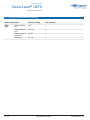
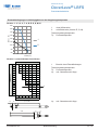
Process conditions as a function of the ambient temperature
Type 1, 2, 3, 4, 6, 7, A, B, E, G, K, M, N
80
90
100
110
120
130
140
150
160
50 60 70 80 90
Tp max. (°C)
Tamb (°C)
1
2
1 without cooling neck
2 with cooling neck (version E, G, M)
Tamb Ambient temperature
Tp Process temperature
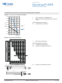
Version L (adjustable connection)
200 25 35 50 65 90 145
190 20 35 45 65 90 140
180 20 30 45 60 85 140
170 20 25 40 55 85 135
160 25 35 55 80 130
150 20 25 50 75 130
140 20 30 45 75 125
130 25 45 70 120
120 20 40 65 115
110 20 25 60 110
100 30 55 105
90 25 50 100
80 20 45 95
70 35 85
60 35 65
35 40 45 50 55 60 65
Lp (mm)
Tp max. (°C)
Tamb (°C)
1
1 Range without restrictions
Tamb Ambient temperature
Tp Process temperature
Lp min. projecting length:
Lp 15…228
15
15
≤ 228 34
34≥ 15 Lp min. projecting length:
www.baumer.com 15 / 48

Operating Instructions
Level measurement
CleverLevel® LBFS
Point level detection
15. Factory settings and user settings
Sensor parameter Factory setting User setting
SW1
(NO)
Switch window,
min.
0%
Switch window,
max.
75.3%
Switch window
hysteresis
2.4%
Damping 0.1 s
16 / 48 www.baumer.com

Inhaltsverzeichnis
Inhaltsverzeichnis ................................................17
1. Sicherheit ...................................................17
2. Aufbau und Funktion ..................................17
3. Symbole in Warnhinweisen ....................... 18
4. Transport und Lagerung ............................ 18
5. Montage .................................................... 18
6. Zulassungen .............................................. 22
7. Elektrischer Anschluss .............................. 23
8. Elektrischer Anschluss in
explosionsgefährdeten Bereichen ............. 23
9. Konguration ............................................. 26
10. Betrieb ....................................................... 26
11. Reinigung, Wartung und Reparatur ........... 27
12. Entsorgung ................................................ 27
13. Zubehör ..................................................... 27
14. Technische Daten ...................................... 27
15. Werkseinstellungen und
Benutzereinstellungen ............................... 30
1. Sicherheit
Bestimmungsgemässe Verwendung
Der Sensor darf ausschliesslich zur
Füllstandserkennung von Flüssigkeiten und
Feststoffen mit einer Dielektrizitätskonstante von
mindestens 1,5 verwendet werden.
Der Sensor darf nur für Medien eingesetzt
werden, gegen die das Gehäusematerial und die
Sensorspitze resistent sind.
Personalqualikation
Nur Personal einsetzen, das für die beschriebenen
Tätigkeiten geschult ist. Dies gilt insbesondere
für Montage, Installation und Explosionsschutz.
Sicherstellen, dass das Personal diese Anleitung
gelesen und verstanden hat.
Technischer Zustand
Sensor nur in einwandfreiem technischen Zustand
verwenden. Nur Zubehör von Baumer verwenden.
Für Zubehör anderer Hersteller übernimmt Baumer
keine Haftung.
Verbrennungsgefahr bei heissen Medien
Das Gehäuse des Sensors kann sich im Betrieb
auf über 50 °C erwärmen. Bei heissen Medien für
Verbrennungsschutz sorgen.
Explosionsgefährdeter Bereich
Sicherstellen, dass sicherheitstechnische Auagen
eingehalten werden. Geräte, die harten Stössen
ausgesetzt wurden, nicht verwenden.
2. Aufbau und Funktion
1 2 3
Abb. 1. Aufbau
fL
C
µC
Abb. 2. Funktion
1 Sensorspitze
2 LED
3 Anschluss mit Stecker M12-A, 4-Pin oder
Kabelabgang
Eine in die Sensorspitze integrierte Elektrode
bildet zusammen mit der Umgebung einen
Kondensator. Das Medium bestimmt abhängig
von seiner Dielektrizitätskonstanten (DK-Wert)
den Kapazitätswert. Zusammen mit einer Spule in
der Sensorelektronik entsteht ein Resonanzkreis.
Abhängig von der gemessenen Resonanzfrequenz
und den programmierbaren Triggerschwellen wird
das Schaltsignal angesteuert.
www.baumer.com 17 / 48
Füllstandsmessung
CleverLevel® LBFS
Grenzstandsdetektion
Betriebsanleitung

3. Symbole in Warnhinweisen
Symbol Warnwort Erklärung
GEFAHR Bei Situationen, die zum Tod oder zu schweren Verletzungen führen.
WARNUNG Bei Situationen, die zum Tod oder zu schweren Verletzungen führen können.
VORSICHT Bei Situationen, die zu leichten oder mittel schweren Verletzungen führen
können.
ACHTUNG Bei Sachschäden
4. Transport und Lagerung
fVerpackung und Sensor auf Beschädigungen
prüfen.
fBei Beschädigung: Sensor nicht verwenden.
fSensor stosssicher lagern.
Lagertemperatur: –40…+85 °C
Relative Luftfeuchtigkeit: < 98 %
5. Montage
2
4
1
3
4
4
Abb. 3. Generelle Einbaumöglichkeiten
1 Überfüllsicherung
2 Grenzstand max.
3 Grenzstand min.
4 Trockenlaufschutz
Der Sensor kann in jeder beliebigen Lage am
Behälter montiert werden.
Ein oben am Behälter montierter Sensor (1) sichert
gegen Überfüllung. Weiter unten angebrachte
Sensoren erkennen einen maximalen (2) oder
minimalen (3) Grenzstand. Ein unten oder am
Auslaufrohr angebrachter Sensor (4) kann eine
Pumpe vor Trockenlauf schützen.
18 / 48 www.baumer.com
Füllstandsmessung
CleverLevel® LBFS
Grenzstandsdetektion
Betriebsanleitung

1
2
3
Abb. 4. Einbau verlängerter Sensoren
1 Grenzstand: Einbau mit Rohr (Version 5)
2 Überfüllsicherung (Version K, L)
3 Pastöse oder pulverförmige Medien
Grenzstand (Version K, L)
Eintauchlänge:
Version K: 82 mm (x)
Version L: 15…228 mm (verschiebbar)
Mit der verschiebbaren Version L kann eine
Tankisolierung überbrückt werden.
Bei pastösen oder pulverförmigen Medien wird
der Sensor durch eine grössere Eintauchtiefe
unempndlicher gegen Anbackungen.
5.1 Montage bei Industrieanwendungen
GEFAHR
Verletzungsgefahr durch gefährliches Medium
fBei gefährlichen Medien (z. B. Säuren, Laugen) Schutzausrüstung tragen.
fBehälter und Rohrleitungen vor der Montage leeren.
PTFE
1
2
LBFS mit folgenden Prozessanschlüssen:
G 1/2 A ISO 228-1 BSC (BCID G07)
G 3/4 A ISO 228-1 (BCID G10)
G 1 A ISO 228-1 (BCID G11)
1/2-14 NPT (BCID N02)
3/4-14 NPT (BCID N03)
9Behälter und Rohrleitungen sind medienfrei.
fGewinde am Sensor mit Teonband (PTFE)
abdichten.
fSensor einschrauben.
Anzugsmoment G xx A: 30 Nm max.
Anzugsmoment xx-14 NPT: 20 Nm max.
www.baumer.com 19 / 48
Füllstandsmessung
CleverLevel® LBFS
Grenzstandsdetektion
Betriebsanleitung

LBFS mit folgenden Prozessanschlüssen:
G 1/2 A ISO 228-1 BSC (BCID G07)
mit industrieller Einschweissmuffe für
Universaleinsatz Ø 30 x 26 (ZPW1-711,
ZPW1-721)
G 1/2 A hygienegerecht (BCID A03) mit
Einschweissmuffe oder Adapter von Baumer
Bei diesen Prozessanschlüssen wird nicht mit
Teonband (PTFE) oder Elastomer abgedichtet.
9Behälter und Rohrleitungen sind medienfrei.
9Adapter oder Einschweissmuffe sind totraumfrei
montiert.
fSensor einschrauben.
Anzugsmoment: 15…20 Nm
1
2
LBFS mit folgenden Prozessanschlüssen:
G 1/2 A DIN 3852-E (BCID G51)
9Behälter und Rohrleitungen sind medienfrei.
fDichtring aufschieben.
fSensor einschrauben.
Anzugsmoment: 15…20 Nm
1
2
LBFS mit folgenden Prozessanschlüssen:
G 1/2 A ISO 228-1 für Innenmontage (BCID T10)
9Behälter und Rohrleitungen sind medienfrei.
fDichtring aufschieben.
fSensor einschrauben.
Anzugsmoment: 15…20 Nm
20 / 48 www.baumer.com
Füllstandsmessung
CleverLevel® LBFS
Grenzstandsdetektion
Betriebsanleitung
Seite wird geladen ...
Seite wird geladen ...
Seite wird geladen ...
Seite wird geladen ...
Seite wird geladen ...
Seite wird geladen ...
Seite wird geladen ...
Seite wird geladen ...
Seite wird geladen ...
Seite wird geladen ...
Seite wird geladen ...
Seite wird geladen ...
Seite wird geladen ...
Seite wird geladen ...
Seite wird geladen ...
Seite wird geladen ...
Seite wird geladen ...
Seite wird geladen ...
Seite wird geladen ...
Seite wird geladen ...
Seite wird geladen ...
Seite wird geladen ...
Seite wird geladen ...
Seite wird geladen ...
Seite wird geladen ...
Seite wird geladen ...
Seite wird geladen ...
Seite wird geladen ...
-
 1
1
-
 2
2
-
 3
3
-
 4
4
-
 5
5
-
 6
6
-
 7
7
-
 8
8
-
 9
9
-
 10
10
-
 11
11
-
 12
12
-
 13
13
-
 14
14
-
 15
15
-
 16
16
-
 17
17
-
 18
18
-
 19
19
-
 20
20
-
 21
21
-
 22
22
-
 23
23
-
 24
24
-
 25
25
-
 26
26
-
 27
27
-
 28
28
-
 29
29
-
 30
30
-
 31
31
-
 32
32
-
 33
33
-
 34
34
-
 35
35
-
 36
36
-
 37
37
-
 38
38
-
 39
39
-
 40
40
-
 41
41
-
 42
42
-
 43
43
-
 44
44
-
 45
45
-
 46
46
-
 47
47
-
 48
48


