Axis Communications 18613 Benutzerhandbuch

Kategorie
Sicherheitskameras
Typ
Benutzerhandbuch

Dieses Handbuch ist auch geeignet für

ENGLISH
FRANCAIS
DEUTSCH
ESPAÑOL
ITALIANO
AXIS 216FD
AXIS 216FD-V
AXIS 216MFD
AXIS 216MFD-V
Fixed Dome Network Camera
Installation Guide
AXIS 216FD/216FD-V/216MFD/216MFD-V Installation Guide Page 3
ENGLISH
ENGLISH
AXIS 216FD/216FD-V
AXIS 216MFD/216MFD-V
Installation Guide
This installation guide provides instructions for installing the AXIS 216FD, AXIS 216FD-V,
AXIS 216MFD and AXIS 216MFD-V Fixed Network Dome Camera on your network. For all
other aspects of using the product, please see the User’s Manual, available on the CD
included in this package, or from www.axis.com/techsup
Installation steps
1. Check the package contents against the list below.
2. Hardware overview. See page 4.
3. Install the hardware. See page 5.
4. Assign an IP address. See page 7.
5. Set the password. See page 10.
6. Adjust the focus. See page 11.
7. Complete the installation. See page 11.
Package contents
Item Models/variants/notes
Fixed Dome Network camera AXIS 216FD: tamper-resistant casing
AXIS 216FD-V: vandal-resistant casing
AXIS 216MFD: tamper-resistant casing
AXIS 216MFD-V: vandal-resistant casing
PS-H indoor power supply
(country specific)
Europe
UK
Australia
USA/Japan
Argentina
Korea
Power supply extension cable 1.8 meters
Terminal block connector 4-pin connector block for connecting external devices to the I/O terminal
connector
Mounting kit Screwdriver for tamper-proof screws
Tamper-proof screws
Drill template
CD AXIS Network Video Product CD, including product documentation,
installation tools and other software
Printed Materials AXIS 216FD/216FD-V/216MFD/216MFD-V Installation Guide (this document)
Axis Warranty Document
Important!
This product must be used in
compliance with local laws
and regulations.
Page 4 AXIS 216FD/216FD-V/216MFD/216MFD-V Installation Guide
Hardware overview
Product ID & Serial number (S/N).
The serial number may be
required during the installation.
Dimensions
HxWxD = 94 x 144 x 132mm (3.7" x 5.7" x 5.2")
Weight AXIS 216FD/AXIS 216MFD = 425g (0.94 lb) (power supply not included)
Weight AXIS 216FD-V/216MFD-V = 580g (1.28 lb) (power supply not included)
Cover plates
Network
indicator LED
Status indicator LED
Control button
Power connector
(see page 14)
Network
connector
(see page 14)
I/O terminal connector
(see page 14)
Power
indicator LED
Audio out
Audio in
Microphone
16mm cable conduit
(not supplied) fitted to
AXIS 216FD-V/216MFD-V
AXIS 216FD/216FD-V/216MFD/216MFD-V Installation Guide Page 5
ENGLISH
ENGLISH
Install the hardware
Mount the camera
The AXIS 216FD/216FD-V/216MFD/216MFD-V can be mounted with the cables routed
through the wall/ceiling, or from above or below. There are cover plates for the openings on
both sides of the dome cover. The AXIS 216FD-V/216MFD-V can also be fitted with a metal
conduit for protecting the cabling when connected via the side openings. See the
illustrations on page 4.
1. Using the drill template, drill two holes in the ceiling/wall.
2. Route and connect all the required cables. See Connect the cables, below.
3. Fasten the camera unit to a ceiling or wall, using screws and plugs appropriate for the
ceiling/wall material.
4. Ensure the camera is positioned so that the tamper-proof screws can be tightened using
the supplied screwdriver.
Mounting on a hard ceiling
To mount the AXIS 216FD/216FD-V/216MFD/216MFD-V on a hard ceiling, check that the
ceiling material is sturdy enough to hold the weight of the camera.
The camera can also be secured using a plate or board that better carries the weight of the
camera, and which is more suitable for securing the screws.
The AXIS 216FD/AXIS 216MFD can also be mounted using the AXIS 216FD/AXIS 216MFD
Drop Ceiling Mount, which allows the camera to be mounted more discreetly. Please see
www.axis.com for all available mounting accessories.
!
IMPORTANT! - The casing of the AXIS 216FD/216FD-V/216MFD/216MFD-V
is not approved for outdoor use - the product may only be installed in indoor
environments.
Plate or
Hard ceiling
AXIS 216FD/216FD-V
Screws
board
216MFD/216MFD-V
Page 6 AXIS 216FD/216FD-V/216MFD/216MFD-V Installation Guide
Connect the cables
1. Connect the camera to the network using a shielded network cable.
2. Optionally connect external input/output devices, e.g. alarm devices. See page 14 for
information on the terminal connector pins.
3. Optionally connect an active speaker and/or external microphone.
4. Connect power, using one of the methods listed below:
PoE (Power over Ethernet). If available, this is automatically detected when the
network cable is connected (see above).
Connect the supplied indoor power supply to the power connector on the camera.
5. Check that the indicator LED:s indicate the correct conditions. See the table on page 15
for further details. Note that some LEDs can be disabled and may be unlit.
AXIS 216FD/216FD-V/216MFD/216MFD-V Installation Guide Page 7
ENGLISH
ENGLISH
Assign an IP address
Most networks today have a DHCP server that automatically assigns IP addresses to
connected devices. If your network does not have a DHCP server the AXIS 216FD/216FD-V/
216MFD/216MFD-V will use 192.168.0.90 as the default IP address.
If you would like to assign a static IP address the recommended method in Windows is either
AXIS IP Utility or AXIS Camera Management. Depending on the number of cameras you
wish to install, use the method that best suits your purpose.
Both of these free applications are available on the Axis Network Video Product CD supplied
with this product, or they can be downloaded from www.axis.com/techsup
Notes:
If assigning the IP address fails, check that there is no firewall blocking the operation.
For other methods of assigning or discovering the IP address of the AXIS 216FD/216FD-V/216MFD/
216MFD-V, e.g. in other operating systems, see page 13.
Method Recommended for Operating system
AXIS IP Utility
See page 8
Single camera
Small installations
Windows
AXIS Camera Management
See page 9
Multiple cameras
Large installations
Installation on a different subnet
Windows 2000
Windows XP Pro
Windows 2003 Server
Page 8 AXIS 216FD/216FD-V/216MFD/216MFD-V Installation Guide
AXIS IP Utility - single camera/small installation
AXIS IP Utility automatically discovers and displays Axis devices on your network. The
application can also be used to manually assign a static IP address.
Note that the computer running AXIS IP Utility must be on the same network segment
(physical subnet) as the AXIS 216FD/216FD-V/216MFD/216MFD-V.
Automatic discovery
1. Check that the AXIS 216FD/216FD-V/216MFD/216MFD-V is connected to the network
and that power has been applied.
2. Start AXIS IP Utility.
3. When the camera appears in the window, double-click it to open its home page.
4. See page 10 for instructions on how to assign the password.
Assign the IP address manually (optional)
1. Acquire an unused IP address on the same network segment as your computer.
2. Select the AXIS 216FD/AXIS 216MFD in the list.
3. Click the button Assign new IP address to the selected device and enter the IP
address.
4. Click the Assign button and follow the instructions.
5. Click the Home Page button to access the camera’s web pages.
6. See page 10 for instructions on how to set the password.
Note:
AXIS 216FD and AXIS 216FD-V will display in AXIS Camera Management as
AXIS 216FD. AXIS 216MFD and AXIS 216MFD-V will display in AXIS Camera
Management as AXIS 216MFD.
AXIS 216FD/216FD-V/216MFD/216MFD-V Installation Guide Page 9
ENGLISH
ENGLISH
AXIS Camera Management - multiple cameras/large installations
AXIS Camera Management can automatically discover multiple Axis devices, show
connection status, manage firmware upgrades and set IP addresses.
Automatic discovery
1. Check that the camera is connected to the network and that power has been applied.
2. Start AXIS Camera Management. When the AXIS 216FD/AXIS 216MFD appears in the
window, double-click it to open the camera’s home page.
3. See page 10 for instructions on how to set the password.
Assign an IP address in a single device
1. Select AXIS 216FD/AXIS 216MFD in AXIS Camera Man-
agement and click the Assign IP button.
2. Select Assign the following IP address and enter the IP
address, the subnet mask and default router the device
will use.
3. Click the OK button.
Assign IP addresses in multiple devices
AXIS Camera Management speeds up the process of
assigning IP addresses to multiple devices, by suggesting IP
addresses from a specified range.
1. Select the devices you wish to configure (different mod-
els can be selected) and click the Assign IP button.
2. Select Assign the following IP address range and enter
the range of IP addresses, the subnet mask and default
router the devices will use.
3. Click the OK button.
Note:
AXIS 216FD and AXIS 216FD-V will display in AXIS Camera Management as
AXIS 216FD. AXIS 216MFD and AXIS 216MFD-V will display in AXIS Camera
Management as AXIS 216MFD.
Page 10 AXIS 216FD/216FD-V/216MFD/216MFD-V Installation Guide
Set the password
When accessing the AXIS 216FD/216FD-V/
216MFD/216MFD-V for the first time, the
Configure Root Password’ dialog will be
displayed.
1. Enter a password and then re-enter it, to con-
firm the spelling. Click OK.
2. Enter the user name root in the Enter
Network Password’ dialog.
Note: The default administrator user name root cannot be deleted.
3. Enter the password as set above, and click OK. If the password is lost, the AXIS 216FD/
216FD-V/216MFD/216MFD-V must be reset to the factory default settings. See page 16.
4. If required, click Yes to install AMC (AXIS Media Control), which allows viewing of the
video stream in Internet Explorer. You will need administrator rights on the computer to
do this.
The Live View page of the AXIS 216FD/216FD-V/216MFD/216MFD-V is displayed, with
links to the Setup tools, which allow you to customize the camera. Note that both AXIS
216FD/216FD-V will display in the browser as AXIS 216FD and AXIS 216MFD/216MFD-V
will display in the browser as the AXIS 216MFD.
Setup - Provides all the tools for configuring
the camera to requirements.
Help - Displays
online help on all
aspects of using
the camera.
AXIS 216FD/216FD-V/216MFD/216MFD-V Installation Guide Page 11
ENGLISH
ENGLISH
Adjust the image and focus
Open the Live View page in the web interface and make the following adjustments to the
camera:
1. Loosen the locking screw and
tilt adjustment screws.
2. Turn the lens to the desired
position.
3. Once satisfied, gently tighten
the locking screw and tilt
adjustment screws to secure
the camera’s position.
4. Turn the image balance ring
to set the horizontal position.
5. Open the Focus Adjustment
page in the Web interface
under Basic Configuration >
Focus and follow the on-
screen instructions. Use the
image window to adjust the
focus and zoom.
6. To set the focus and zoom,
loosen the zoom and focus pullers anti-clockwise and rotate the rings.
Note:
Due to the dome’s refraction, the image might appear slightly out of focus once
the dome has been placed. To compensate, focus on an object slightly closer than
the inteded area.
7. Lock the focus and zoom pullers in position by rotating the screws clockwise.
The image can also be fine-tuned for low lighting conditions.
Go to Setup > Video & Image > Advanced and see the online help for more information.
Complete the installation
1. Rotate the black protective shield inside the dome casing to match the camera’s position.
2. Clean the dome with a dry soft cloth to remove dust and finger prints and use a blower
to remove dust from the lens.
3. Mount the dome casing using the supplied tamper-proof screws and screw driver.
4. Now that the dome is in place, double-check that the camera is properly focused.
5. The installation is now complete.
Image
Focus puller
Zoom puller
screw
Tilt adjustment
screw
Tilt adjustment
balance
ring
Locking screw
Page 12 AXIS 216FD/216FD-V/216MFD/216MFD-V Installation Guide
Accessing the camera from the Internet
Once installed, your AXIS 216FD/216FD-V/216MFD/216MFD-V is accessible on your local
network (LAN). To access the camera from the Internet, network routers must be configured
to allow incoming traffic, which is usually done on a specific port. Please refer to the
documentation for your router for further instructions. For more information on this and
other topics, visit the Axis Support Web at www.axis.com/techsup
AXIS 216FD/216FD-V/216MFD/216MFD-V Installation Guide Page 13
ENGLISH
ENGLISH
Other methods of setting the IP address
The table below shows the other methods available for setting or discovering the IP address.
All methods are enabled by default, and all can be disabled.
Set the IP address with ARP/Ping
1. Acquire an IP address on the same network segment your computer is connected to.
2. Locate the serial number (S/N) on the AXIS 216FD/216FD-V/216MFD/216MFD-V label.
3. Open a command prompt on your computer and enter the following commands:
4. Check that the network cable is connected to the camera and then start/restart the
camera, by disconnecting and reconnecting power.
5. Close the command prompt when you see ‘Reply from 192.168.0.125: ...’ or similar.
6. In your browser, type in http://<IP address> in the Location/Address field and press Enter
on your keyboard.
Notes:
To open a command prompt in Windows: from the Start menu, select Run... and type cmd. Click OK.
To use the ARP command on a Mac OS X, use the Terminal utility in Application > Utilities.
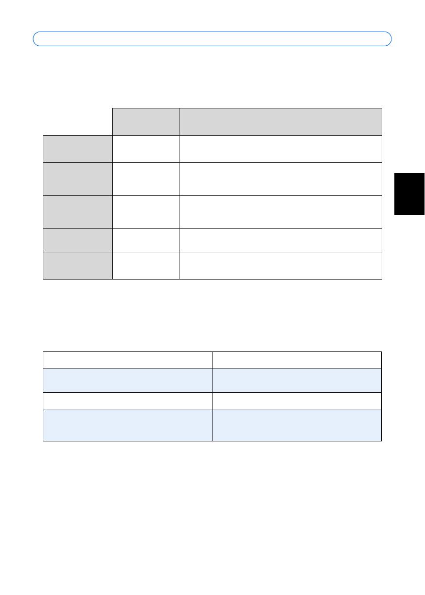
Use in operating
system
Notes
UPnP™
Windows
(ME or XP)
When enabled on your computer, the camera is automatically
detected and added to “My Network Places.”
Bonjour
MAC OSX
(10.4 or later)
Applicable to browsers with support for Bonjour. Navigate to the
Bonjour bookmark in your browser (e.g. Safari) and click on the
link to access the camera’s web pages.
AXIS Dynamic DNS
Service
All A free service from Axis that allows you to quickly and simply
install your camera. Requires an Internet connection with no
HTTP proxy. See www.axiscam.net for more information.
ARP/Ping
All See below. The command must be issued within 2 minutes of
connecting power to the camera.
View DHCP server
admin pages
All To view the admin pages for the network DHCP server, see the
server’s own documentation.
Windows syntax Windows example
arp -s <IP Address> <Serial Number>
ping -l 408 -t <IP Address>
arp -s 192.168.0.125 00-40-8c-18-10-00
ping -l 408 -t 192.168.0.125
UNIX/Linux/Mac syntax UNIX/Linux/Mac example
arp -s <IP Address> <Serial Number> temp
ping -s 408 <IP Address>
arp -s 192.168.0.125 00:40:8c:18:10:00
temp
ping -s 408 192.168.0.125
Page 14 AXIS 216FD/216FD-V/216MFD/216MFD-V Installation Guide
Unit connectors
Network connector - RJ-45 Ethernet connector. Supports Power over Ethernet. Using
shielded cables is recommended.
Power connector - Mini DC connector. 5.1V DC, max 3.8W. See product label for
±
connection.
Audio in - 3.5mm input for a mono microphone, or a line-in mono signal (left channel is
used from a stereo signal).
Audio out - Audio output (line level) that can be connected to a public address (PA) system
or an active speaker with a built-in amplifier. A pair of headphones can also be attached. A
stereo connector must be used for the audio out.
I/O terminal connector - Used in applications for e.g. motion detection, event triggering,
time lapse recording and alarm notifications. It provides the interface to:
1 transistor output - For connecting external devices such as relays and LEDs.
Connected devices can be activated by AXIS VAPIX AP, output buttons on the
Live View page or by an Event Type. The output will show as active (shown
under Event Configuration > Port Status) if the alarm device is activated.
1 digital input - An alarm input for connecting devices that can toggle between
an open and closed circuit, for example: PIRs, door/window contacts, glass break
detectors, etc. When a signal is received the state changes and the input becomes
active (shown under Event Configuration > Port Status).
Auxiliary power and GND
Function Pin number Notes Specifications
GND 1
3.3V DC
Power
2 Can be used to power auxiliary equipment.
Note: This pin can only
be used as power out.
Max load = 50mA
Digital Input 3 Connect to GND to activate, or leave floating
(or unconnected) to deactivate.
Must not be exposed to
voltages greater than
10V DC
Transistor
Output
4 Uses an open-collector NPN transistor with
the emitter connected to the GND pin. If used
with an external relay, a diode must be con-
nected in parallel with the load, for protection
against voltage transients.
Max load = 50mA
Max voltage = 24V DC
(to the transistor)
AXIS 216FD/216FD-V/216MFD/216MFD-V Installation Guide Page 15
ENGLISH
ENGLISH
Connection diagram
LED indicators
LED Color Indication
Network Green Steady for connection to a 100 Mbit/s network. Flashes for network activity.
Amber Steady for connection to 10 Mbit/s network. Flashes for network activity.
Unlit No network connection.
Status Green Steady green for normal operation.
Note: The Status LED can be configured to be unlit during normal operation, or to
flash only when the camera is accessed. To configure, go to Setup > System
Options > LED settings. See the online help files for more information.
Amber Steady during startup, during reset to factory default or when restoring settings.
Red Slow flash for failed upgrade.
Power Green Normal operation.
Amber Flashes green/amber during firmware upgrade.
o
z
AXIS 216FD/216FD-V/216MFD/216MFD-V
3.3V
max. 50mA
e.g. pushbutton
4
o
3
o
o
2
1
Page 16 AXIS 216FD/216FD-V/216MFD/216MFD-V Installation Guide
Resetting to the Factory Default Settings
This will reset all parameters, including the IP address, to the Factory Default settings:
1. Disconnect power from the camera.
2. Press and hold the Control button and reconnect power.
3. Keep the Control button pressed until the Power indicator flashes amber (this may take
up to 15 seconds).
4. Release the Control button. When the Power indicator displays green (which can take up
to 1 minute) the process is complete and the camera has been reset.
5. Re-assign the IP address, using one of the methods described in this document.
It is also possible to reset parameters to the original factory default settings via the web
interface. For more information, please see the online help or the user’s manual.
Further information
The user’s manual is available from the Axis Web site at www.axis.com or from the Axis
Network Video Product CD supplied with this product.
Tip!
Visit www.axis.com/techsup to check if there is updated firmware available for your
AXIS 216FD/216FD-V/216MFD/216MFD-V. To see the currently installed firmware
version, see the Basic Configuration web page in the product’s Setup tools.
AXIS 216FD/216FD-V/216MFD/216MFD-V Guide d’installation Page 17
FRANCAIS
AXIS 216FD/216FD-V
AXIS 216MFD/216MFD-V
Guide d'installation
Ce guide d'installation vous explique comment installer la AXIS 216FD, AXIS 216FD-V,
AXIS 216MFD, et AXIS 216MFD-V sur votre réseau. Pour d'autres informations sur
l'utilisation de ce produit, consultez le Manuel de l'utilisateur, disponible sur le CD fourni, ou
visitez le site www.axis.com/techsup
Étapes de l'installation
1. Vérifiez le contenu de la livraison à l'aide de la liste ci-dessous.
2. Présentation du matériel. Reportez-vous à la page 18.
3. Installez le matériel. Reportez-vous à la page 19.
4. Paramétrez une adresse IP. Reportez-vous à la page 21.
5. Définissez le mot de passe. Reportez-vous à la page 24.
6. Réglez la mise au point. Reportez-vous à la page 25.
7. Complétez l'installation. Reportez-vous à la page 25.
Contenu de l'emballage
Article Modèles/variantes/remarques
Caméra réseau AXIS 216FD: boitier invoyable
AXIS 216FD-V: boitier a l'épreuve du vandalisme
AXIS 216MFD: boitier invoyable
AXIS 216MFD-V: boitier a l'épreuve du vandalisme
Alimentation intérieure
PS-H
(dépend du pays)
Europe
Royaume-Uni
Australie
États-Unis/Japon
Argentine
Corée
Prolongateur de câble
d’alimentation
1,8 mètres
Connecteur pour ter-
minaux
Connecteur 4 broches pour la connexion d'équipements externes au connecteur E/S
Kit de montage Tournevis pour vis inviolables
Vis inviolables
Gabarit de perçage
CD CD de la caméra vidéo réseau Axis comprenant les outils d'installation, les autres logiciels et la
documentation
Documentation AXIS 216FD/216FD-V/216MFD/216MFD-V Guide d'installation (le présent document)
Document de garantie d'Axis
Important !
Ce produit doit être utilisé
conformément aux lois et
dispositions locales en
vigueur.
Page 18 AXIS 216FD/216FD-V/216MFD/216MFD-V Guide d’installation
Présentation du matériel
D
imensions
H x L x P = 94 x 144 x 132mm
Poids AXIS 216FD/AXIS 216MFD = 425g (alimentation exclue)
Poids AXIS 216FD-V/216MFD-V = 580g (alimentation exclue)
Connecteur de
réseau
(reportez-vous à la
page 28)
Connecteur
d'alimentation
(reportez-vous
à la page 28)
Témoin DEL d’état
ID du produit et numéro de
série (S/N). Le numéro de
série peut être requis
pendant l'installation.
Témoin
DEL réseau
Bouton de
commande
Témoin DEL
d’alimentation
Capot plaques
Conduit de 16mm (non
fourni) adaptable à
AXIS
216FD-V/216MFD-V
Connecteur pour terminaux E/S
(reportez-vous à la page 28)
Entrée
audio
Sortie
audio
Microphone
AXIS 216FD/216FD-V/216MFD/216MFD-V Guide d’installation Page 19
FRANCAIS
Installation du matériel
Montage de la caméra
La caméra AXIS 216FD/216FD-V/216MFD/216MFD-V peut être montée avec les câbles
d'alimentation et réseau acheminés dans le mur/plafond, ou depuis le haut ou le bas. Vous
disposez de plaques d'obturation pour les ouvertures des deux côtés du capot du dôme.
L’AXIS 216FD-V/216MFD-V peut aussi equipé avec un conduit en métal afin de protéger le
câblage lorsqu'il est connecté par les ouvertures latérales. Consultez les figures de la page 18.
1. Avec le gabarit de perçage, percez deux trous dans le plafond/mur.
2. Orienter et connecter tous les câbles néccessaires. Voi Branchement des câbles, en bas.
3. Fixez la caméra au plafond ou au mur à l'aide des vis et des chevilles appropriées.
4. Veillez à ce que la caméra soit positionnée de telle manière que les vis inviolables
puissent être serrées à l'aide du tournevis fourni.
Montage au plafond dur
Pour monter l’AXIS 216FD/216FD-V/216MFD/216MFD-V au plafond dur, vérifier si le
materiau du plafond est assez solid pour soutenir le poids de la caméra.
Pour fixer la caméra, vous pouvez utiliser une plaque ou une carte supportant le poids de la
caméra, qui sera plus adaptée à la fixation des vis.
The AXIS 216FD/AXIS 216MFD peut aussi être montée à l'aide de l’AXIS 216FD/AXIS
216MFD Drop Ceiling Mount, qui permet de placer la caméra plus discrètement. Voir
www.axis.com pour les accessoires de montage disponibles.
!
IMPORTANT! - Le boitier de l'AXIS 216FD/216FD-V/216MFD/216MFD-V
n'est pas approuvé pour une utilisation extérieure - Le produit doit être
uniquement installé en intérieur.
Plaque ou
plafond dur
AXIS 216FD/216FD-V
Vis
carte
216MFD/216MFD-V
Page 20 AXIS 216FD/216FD-V/216MFD/216MFD-V Guide d’installation
Branchement des câbles
1. Connectez la caméra à votre réseau à l'aide d'un câble de réseau blindé.
2. Si vous le souhaitez, connectez des dispositifs externes, par exemple des dispositifs d'alarme.
Reportez-vous à la page 28 pour plus d'informations sur les broches du connecteur pour
terminaux.
3. Si vous le souhaitez, connectez un haut-parleur actif pour la transmission audio
bidirectionnelle.
4. Branchez l'alimentation à l'aide de l'une des méthodes reprises ci-dessous.
PoE (Alimentation éléctrique par câble ethernet). Si disponible, ceci est automa-
tiquement détecté quand le câble résau est connecté (Voir au -dessus).
Branchez l'alimentation intérieure fournie au connecteur d'alimentation de la caméra.
5. Vérifiez que les témoins DEL indiquent les conditions correctes. Pour plus d'informations,
consultez le tableau à la page 29. Notez que certains témoins DEL peuvent être désactivés et
éteints.
  • Page 1 1
  • Page 2 2
  • Page 3 3
  • Page 4 4
  • Page 5 5
  • Page 6 6
  • Page 7 7
  • Page 8 8
  • Page 9 9
  • Page 10 10
  • Page 11 11
  • Page 12 12
  • Page 13 13
  • Page 14 14
  • Page 15 15
  • Page 16 16
  • Page 17 17
  • Page 18 18
  • Page 19 19
  • Page 20 20
  • Page 21 21
  • Page 22 22
  • Page 23 23
  • Page 24 24
  • Page 25 25
  • Page 26 26
  • Page 27 27
  • Page 28 28
  • Page 29 29
  • Page 30 30
  • Page 31 31
  • Page 32 32
  • Page 33 33
  • Page 34 34
  • Page 35 35
  • Page 36 36
  • Page 37 37
  • Page 38 38
  • Page 39 39
  • Page 40 40
  • Page 41 41
  • Page 42 42
  • Page 43 43
  • Page 44 44
  • Page 45 45
  • Page 46 46
  • Page 47 47
  • Page 48 48
  • Page 49 49
  • Page 50 50
  • Page 51 51
  • Page 52 52
  • Page 53 53
  • Page 54 54
  • Page 55 55
  • Page 56 56
  • Page 57 57
  • Page 58 58
  • Page 59 59
  • Page 60 60
  • Page 61 61
  • Page 62 62
  • Page 63 63
  • Page 64 64
  • Page 65 65
  • Page 66 66
  • Page 67 67
  • Page 68 68
  • Page 69 69
  • Page 70 70
  • Page 71 71
  • Page 72 72
  • Page 73 73
  • Page 74 74

Axis Communications 18613 Benutzerhandbuch

Kategorie
Sicherheitskameras
Typ
Benutzerhandbuch
Dieses Handbuch ist auch geeignet für