Cooper 29021 LED CG-S Fitting And Operating Instructions
- Typ
- Fitting And Operating Instructions

1
400 71 350 093
Montage- und
Betriebsanleitung
Systemleuchte
Zielgruppe: Elekrofachkräfte
Fitting- and operating
instructions
System luminaire
Target group: Skilled electricians
Style Variant LED
29011 LED CG-S
29021 LED CG-S

2
Inhaltsverzeichnis
Pos. Titel Seite
1 Aufbau 3
1.1 Maßbilder 4
2 Sicherheitshinweise 4
3 Normenkonformität/Verwendung 5
4 Technische Daten 5
5 Installation 5
5.1 Montage 5
5.2 Netzanschluß 5
5.3 Leuchte komplettieren 5
5.4 Überwachungeinrichtung CG-S 6
5.5 Zubehör 6
6 Wartung/Instandhaltung 7
7 Recycling 7
Contents:
Pos. Titel Page
1 Building-up 3
1.1 Dimensional drawings 4
2 Safety instructions 7
3 Conformity with standards 7
4 Technical data 7
5 Installation 8
5.1 Assembly 8
5.2 Mains connection 8
5.3 Complete luminaire 8
5.4 Monitoring devices CG-S 8
5.5 Accessories 8
6 Maintenance / repair 8
7 Recycling 8

3
Piktogrammscheibe
Cover
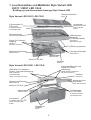
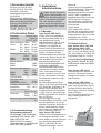
1. Leuchtenaufbau und Maßbilder Style Variant LED
29011 / 29021 LED CG-S
Building-up and dimensional drawings Style Variant LED
Style Variant LED 29011 LED CG-S
Style Variant LED 29021 LED CG-S
Leuchtmittel
Leiste mit 4 LED
Light strip with
4 LED
4 Befestigungs-
schrauben
für Gehäuseoberteil
4 screws for
enclosure top part
Netzanschlußklemmen
Mains terminal
Leitungseinführungen
Cable entries
Löcher für Pendelauf-
hängung
Holes for
pendulum mounting
Gehäuseoberteil
Enclosure top part
Addresschalter
Adress switch
Rastnocken für Wandarm-,
Decken-,und Kettenbefestigung
Snap in tappets
for wall brackets,
ceiling- and chain mounting
Netzanschlußklemmen
Mains terminal
Adresschalter
Address switch
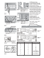
Gehäuse
Enclose
Leitungseinführungen und
Löcher für Pendel-
aufhängung
Cable entries and holes for
pendulum mounting
Abdeckung oben
über Modul
Cover top for modul
Piktogramm-
scheiben
Cover
Leuchtmittel
2 Leisten mit je 4 LED
2 light strip each with
4 LED
Modul 2L-CG-SL4
Modul 2L-CG-SL8
2 Klemmhalter für
LED-Leiste
2 clamping retainer
for LED light strip
2 Klemmhalter
für LED-Leiste
2 clamping retainer
for LED light strip
IP 54 Dichtung (optional)
Gehäuse
Enclosure

4
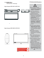
1.1 Maßbilder
Dimensional drawings
Style Variant LED 29011 LED CG-S
Style Variant LED 29021 LED CG-S
Bild 2
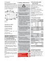
2.Sicherheitshinweise
Die Leuchte ist bestim-
mungsgemäß in unbeschä-
digtem und einwandfreiem
Zustand zu betreiben!
Als Ersatz dürfen nur
Originalteile von CEAG
verwendet werden!
Bei Durchführung von
Arbeiten an der Notleuchte
sicherstellen, daß die Not-
leuchte spannungsfrei
geschaltet ist!
Beachten Sie dabei die
unterschiedlichen Ver-
sorgungen der Notleuchte
bei Normal- und Batterie-
betrieb. Bild 2 zeigt das
Hinweisschild auf der Not-
leuchte.
Vor der ersten Inbetrieb-
nahme muß die Leuchte
entsprechend den im Ab-
schnitt Installation genann-
ten Anweisungen geprüft
werden!
Die Notleuchtenkenn-
zeichnung vornehmen:
Stromkreis und Leuchten-
nummer.
Die Prüfbuchführung ist
nach den nationalen Vor-
schriften durchzuführen.
Alle Fremdkörper müssen
vor der ersten Inbetrieb-
nahme aus der Leuchte
entfernt werden!
Beachten Sie bei allen
Arbeiten an der Leuchte die
nationalen Sicherheits- und
Unfallverhütungsvorschrif-
ten und die nachfolgenden
Sicherheitshinweise in der
Betriebsanleitung, die mit
einem
versehen sind!

5
3.Normenkonformität
Konform mit: EN 60 598-1,
EN 60 598-2-22, EN 1838,
DIN VDE 0108/10.89.
Niederspannungsrichtlinie
93/68/EWG
EMV-Richtlinie 89/336/EWG.
Hinweis: Trotz CE-Konformität
kann eine gegenseitige Beein-
flussung von Geräten und
Leuchten auftreten.
Gemäß DIN EN ISO 9001 ent-
wickelt, gefertigt und geprüft.
Eingangs- 230/240 VAC
spannung: 50/60 Hz
176-275 VDC
Stromaufnahme:100% 65%
29011 AC: 44mA 32 mA
DC: 28mA 20 mA
29021 AC: 70mA 50 mA
DC: 48mA 34 mA
Leistungsaufnahme (AC):
100% 65%
29011 10.1VA 7,5VA
29021 16,1VA 11,4VA
Nennlichtstrom:
29011 88lm
29021 176lm
Bemessungslichtstrom
100% 65%
29011 79lm 55lm
29021 147lm 104lm
Schutzklasse: II
Schutzart nach
EN 60529: IP 41
optional nur 29011: IP 54
zulässige Umgebungs-
temperatur -10°C..+40°C
Netzanschußklemmen:
2x 2x 2,5 mm²
Gewichte: 29011: 1,1kg
29021: 1,2kg
Abmessungen:siehe Maßbilder
S.4
4.2 Kurzbeschreibung /
Verwendungsbereich
Die Rettungs- und Sicherheits-
leuchten STYLE Variant LED
29011 LED CG-S und
29021 LED CG-S sind als
Systemleuchten in Installationen
nach VDE 0108 geeignet.
5. Installation/
Inbetriebnahme
Halten Sie die für das Er-
richten und Betreiben von
elektrischen Betriebsmitteln gel-
tenden Sicherheitsvorschriften
und das Gerätesicherheits-
gesetz sowie die allgemein an-
erkannten Regeln der Technik
ein!
5.1 Montage
Style Variant LED 29011
Lösen Sie die Schnapphaken
der Piktogrammscheibe mit ei-
nem geeignetem Schlitz-
schraubendreher (Bild 3) und
heben Sie die Piktogramm-
scheibe vom Gehäuse ab.
Lösen Sie die 4 Schrauben mit
einem Kreuzschlitzschrauben-
dreher und heben Sie das
Gehäuseoberteil vom Gehäuse-
unterteil ab. Ziehen Sie den Ste-
cker am Modul ab und legen
das Gehäuseoberteil ab.
Nach Installationsgegebenheit
wahlweise vorgeprägte
Leitungseinführungen seitlich
oder an der Rückseite ausbre-
chen. Leitungseinführungs-
stopfen einsetzen und ein Loch
für den verwendeten Leitungs-
durchmesser einstanzen oder
einschneiden.
Bei Beschädigung der Dicht-
lippen ist die Leitungseinführung
zum Erhalt der Schutzart zu er-
setzen! Nicht benutzte aber
ausgebrochene Leitungseinfüh-
rungen sind mit dem Leitungs-
einführungsstopfen zu verschlie-
ßen (IP-Schutz).
Die Leitungen sind in den
Leuchtenkörper einzuführen und
der Leuchtenkörper ist mit ge-
eigneten Schrauben durch die 4
an den Gehäuseecken liegen-
den Löchern an Wand oder De-
cke zu befestigen (Bild 5).
Style Variant LED 29021
Lösen Sie die Schnapphaken ei-
ner Piktogrammscheibe (wahl-
weise beide) mit einem geeigne-
tem Schlitzschraubendreher
(Bild 3) und heben Sie die
Piktogrammscheibe vom Ge-
häuse ab.
Lösen Sie die Schnapphaken
der trapezförmigen Abdeckung
an der Einführungs- und
Befestigungsseite der Leuchte
(Bild 4). Nach Installations-
gegebenheiten offene Leitungs-
einführung mit Leitungsein-
führungsstopfen verschließen
und ein Loch einstanzen oder
einschneiden.
Details siehe
Style Variant LED 29011!
Leuchte mit geeigneten Schrau-
ben durch die angeformten Be-
festigungsnocken an der Decke
befestigen oder CEAG-
Zubehörteile verwenden (Bild 6).
5.2 Netzanschluss
Style Variant 29011 LED und
Style Variant 29021 LED:
Das Netzkabel ist an den Klem-
men N und L am Modul 2L-CG-
SL4 oder Modul 2L-CG-SL8 an-
zuschließen (Bild (8.1 und 8.2).
5.3 Leuchte komplettieren
Bei gelöstem Stecker der LED-
Leiste diesen wieder am Modul
aufstecken.
Style Variant LED 29011:
Gehäuseoberteil aufsetzen und
mit den 4 Schrauben fixieren.
Piktogrammscheiben einsetzen
und einrasten.
Style Variant LED 29021:
Trapezförmige Abdeckung zwi-
schen den angeformten trapez-
förmigen Blöcken des Gehäu-
ses einlegen und die 4 Schnapp-
haken einrasten.
Die Piktogrammscheibe(n) auf
das Leuchtengehäuse auf-
schnappen.
4.Technische Daten
2
1
Bild 3
Fig. 3

6
1
2
Bild 4
Fig. 4
Befestigungslöcher 29021
Fixing holes
Bild 6
Fig. 6
Adresschalter
Address switch
Adresschalter1 Adresschalter2
Bild 9
Fig. 9
5.4 Überwachung
Zur Überwachung muß jede
Leuchte individuell adressiert
werden.Vor Montage der Pikto-
grammscheiben bei den
Leuchten 29011 und 29021 und
der trapezförmigen Abdeckung
bei der Leuchte 29021 muß mit
einem geeignetem Schrauben-
dreher die gewünschte Adresse
1 bis 20 an den Adresschaltern
eingestellt werden ( Pfeil auf
Zahl, Bild 9). Soll die Leuchte
nicht überwacht werden, ist an
beiden Adress-schaltern die
Adresse „0“ einzustellen.
Lichtstromwahl:
Mit dem Schalter am LED-
Leisten Anschluß kann der
Lichtstrom der LEDs auf 65%
reduziert werden (Bild 10.).
Modul für
29011
Modul für
29021
L
N
Netzanschluß für
29011 LED
Mains connection for
29011 LED
Bild 8.1
Fig. 8.1
L
N
Netzanschluß für
29021 LED
Mains connection for
29021 LED
Bild 8.2
Fig. 8.2
Bild 11LED -Leiste 29011
Fig.11LED strip 29011
Befestigungslöcher 29011
Fixing holes
Bild 5
Fig. 5
Schalter für
Lichtstrom
Switch for
luminous flux
Klemmhalter
Clamping retarder
Bild 10
Fig. 10
Adresschalter 1 Adresschalter 2 Leuchtenadresse
0 0 Überwachung aus
01 1
02 2
....... ....... ......
1010
1111
1212
....... ....... ......
2020
21nicht zulässig
22nicht zulässig
....... ....... ......
29nicht zulässig

7
5.5 Zubehör
Ballschutzkorb für 29011
Der Ballschutzkorb ist durch die
vier Laschen mit vier ausreichend
dimensonierten Schrauben sicher
an der Wand zentriert vor der
Leuchte zu befestigen.
400
300
240
280
348350
H=115
Bild 11
Fig. 11
Kettenbefestigung
Nr. 400 71 350 432
Deckenbefestigung
Nr. 400 71 350 432
Pendelpaar
Nr. 400 71 350 400, ..402, ..404
Wandausleger
Nr. 400 71 350 418
Siehe Bedienungsanleitung
CEAG-Nr.: 11 526 306
Technische Änderungen
vorbehalten!
3.Conformity with
Standards
Conforms to: EN 60 598-1,
EN 60 598-2-22, EN 1838, DIN
VDE 0108/10.89.
Low-voltage directive
93/68/EEC,
EMC directive 89/336/EEC.
Note: In spite of CE conformity,
there may be a mutual
influence on equipment and
luminaires.
Developed, manufactured and
tested in accordance with DIN
EN ISO 9001.
4. Technical data
Input voltage: 230/240 V AC
50/60 Hz
176-275 VDC
Rated current: 100% 65%
29011 AC: 44mA 32mA
DC: 28mA 20mA
29021 AC: 70mA 50mA
DC: 48mA 34mA
Power consumption (AC):
100% 65%
29011 10,1VA 7,5VA
29021 16,1VA 11,4VA
Nominal luminous flux:
29011 88lm
29021 176lm
Rated luminous flux:
100% 65%
29011 79 lm 55lm
29021 147 lm 104lm
Insulation class: II
Protection category acc. to
EN 60529: IP 41
Option (only 29011): IP 54
Admissible ambient
temperature: -10°C...+40°C
Supply terminals 2x 2x 2,5 mm²
Weight: 29011: 1,1kg
29021: 1,2kg
Dimensions: see dimensional
drawing on page 4
4.2 Brief description/
Scope of application
The Exit and Safety luminaires
Style Variant LED 29011 LED
CG-S and 29021 LED CG-S
are suitable for operation on
power supply systems acc. to
VDE 0108.
Fig. 12
Zubehör für 29021
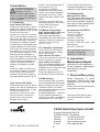
6. Inspektion/War-
tung/Instandhaltung
Halten Sie die für die Inspek-tion,
Wartung und Instandhaltung von
elektrischen Betriebsmitteln
geltenden Bestimmungen ein!
7. Entsorgung / Recy-
cling
Beachten Sie bei der Entsorgung
defekter Geräte die gültigen Vor-
schriften für Recycling und Entsor-
gung.
Kunststoffteile sind mit entspre-
chenden Symbolen gekennzeich-
net.
2. Safety Instructions
The device shall only be
used for its intended purpose
and in undamaged and
perfect condition!
Only genuine CEAG spare
parts may be used for re-
placement and repair!
When working on the emer-
gency luminaire make sure
that it is disconnected from
the voltage! Pay attention to
the different power supplies
in mains or battery
operation. Fig. 12 shows the
indication label on the
emergency luminaire.
Prior to its initial operation,
the luminaire will have to be
checked in accordance with
the instructions as per
section Installation!
Carry out the marking of the
emergency luminaire: Assign
the circuit, the luminaire No.
and enter them.
The log book shall be
performed in compliance
with the national regulations.
Any foreign matter shall be
removed from the luminaire
prior to its initial operation!
Observe the national safety
rules and regulations for pre-
vention of accidents as well
as the safety instructions
included in these operating
instruction marked with

8
CEAG Notlichtsysteme GmbH
Senator-Schwartz-Ring 26
D-59494 Soest / Germany
Telefon +49 29 21/69-870
Telefax +49 29 21/69-617
Internet http:// www.ceag.de
E-mail [email protected]
400 71 350 093 / X /03.05/ CE
5.1 Assembly
Style Variant LED 29011
Loose the snap hooks of the le-
gend cover with a qualified slot-
headed screwdriver (Fig. 3) and
lift the cover from the
enclosure. Loose the 4 screws
with a cross-slotted screwdriver
and lift the top part of enclosure
from the lower part. According
to assembly conditions tweak
out optional the impressed cable
entries sideways or on the back-
side. Enter the sealing stopper
and stamp or cut out a hole for
the using cable diameter. If the
sealing lips are damaged, re-
place the cable entries to main-
tain the protection. Unused cable
entries which are tweaked out
must be closed with sealing
stoppers (IP-degree of protec-
tion).
Insert the cable in the body of
the lamp and attach it through
the 4 holes in the corners of
enclosure to the wall or ceiling
with appropriate screws (Fig. 5).
Style Variant LED 29021
Loose the snap hooks of the le-
gend cover with a qualified slot-
headed screwdriver (Fig. 3) and
lift the cover from the
enclosure. Remove the lamp
from the socket. Loose the
snap hooks of the trapeze
shaped cover at the
entries- and mounting-side of
the luminaire (Fig. 4).
According to assembly
conditions close open cable
entries with sealing stoppers
and stamp or cut out a hole.
Details see Style Variant LED
29011.
Mount the luminaire with ap-
propriate screws to the ceiling
or use CEAG mounting
accessories (Fig. 6).
5.2 Mains Connection
Style Variant 29011 LED and
Style Variant 29021 LED
The mains cable should be
connected to the terminals to the
modul 2L-CG-SL4 or modul 2L-
CG-SL8 N (O) and L (U)
(Fig. 8.1, 8.2).
5.3 Complete Luminaire
Style Variant LED 29011:
Put up the top part of enclosure
and fix it with the 4 screws.
Style Variant Led 29021:
Put in the trapeze shaped cover
between the adjusted trapeze
shaped blocks of enclosure and
snap the 4 snap hooks.
Snap the legend cover(s) on
the enclosure of the luminaire.
5.4 Monitoring
For monitoring each luminaire
must be addressed individually.
Before fitting the covers of the
luminaires 29011 and 29021
and the trapeze shaped cover of
the luminaire 29021,
5.5 Accessories
Chain mounting
No. 400 71 350 432
Ceiling mounting
No. 400 71 350 432
Pendulum mounting
No. 400 71 350 400, ..402, ..404
Wall bracket
No. 400 71 350 418
See operating instruction for
mounting accessories
CEAG no. 11 526 306
If the luminaire should not be
monitored the address „0“ has be
selected on each address switch.
Wire guard for 29011
The wire guard should be firmly
attached to the wall centrally in
front of the luminaire using the
four lugs and four screws of the
appropriate size (Fig.11).
If the plug of the LED-strip is
disconnected please contact
him on the modul.
the desired address (1 - 20) is set
on the address switches by
means of a suitable screwdriver
(arrowhead to no., see fig.9).
Accessories for 29021
5.Installation
For the mounting and
operation of electrical
apparatus, the res-
pective national safety regu-
lations as well as the general
rules of engineering will have
to be observed!
6. Inspection/
Maintenance/Repair
Observe the valid regulations
for the inspection, maintenance
and repair of electrical
equipment!
7. Disposal/Recycling
When disposing of faulty
equipment, observe the valid
regulations for recycling and
disposal.
Plastic parts are marked with the
appropriate symbols.
We reserve the right to make
technical alterations without
notice!
-
 1
1
-
 2
2
-
 3
3
-
 4
4
-
 5
5
-
 6
6
-
 7
7
-
 8
8


Cooper 29021 LED CG-S Fitting And Operating Instructions
- Typ
- Fitting And Operating Instructions
in anderen Sprachen
- English: Cooper 29021 LED CG-S
Verwandte Artikel
Andere Dokumente
-
Eaton CEAG Style Variant 29021 Mounting And Operating Instructions
-
 Hach ORBISPHERE 32301 Basic User Manual
-
-
-
-
Mitsubishi Heavy Industries SC-SL4-AE Installationsanleitung
-
