
VN7640 FlexRay/CAN/LIN/Ethernet Interface
Quick Start Guide
Version 1.1 | English/Deutsch

Quick Start Guide VN7640 ENGLISH
2 Version 1.1 © Vector Informatik GmbH
1 ENGLISH
1.1 Installation
Step by Step Procedure
Please use the drivers from the included Vector Driver Disk.
1. Execute Vector Driver Setup from the autostart menu or directly from
\Drivers\Setup.exe before the device is connected to the PC via USB.
If you have already connected the device to the PC, the Windows found new Hardware
wizard appears. Close this wizard and then execute the driver setup.
2. Finish the driver installation with the setup.
3. If the device has been properly installed, the device can be connected to the PC via USB.
The device is ready for operation now.
4. In order to change the default settings of the channel assignment between the device and an
application, the configuration tool Vector Hardware Config has to be used. The tool can be
found in Windows | Start | Settings | Control Panel | Vector Hardware.
1.2 Further Information
Reference
Further information on the VN7640 interface can be found in the manual on the Vector Driver Disk
in \Documentation.
1.3 Accessories
Reference
Further information on the available accessories can be found in the separate accessories manual
on the Vector Driver Disk in \Documentation\Accessories.

ENGLISH Quick Start Guide VN7640
© Vector Informatik GmbH Version 1.1 3
1.4 Connectors
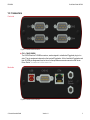
Front side
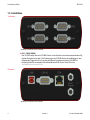
Figure 1: Connectors on the front side
► CH1...CH4 (D-SUB9)
The VN7640 has four D-SUB9 connectors, each assigned to a dedicated Piggyback plug-in loc-
ation. The pin assignments depend on the inserted Piggybacks. A list of available Piggybacks and
their D-SUB9 pin assignments can be found in the separate accessories manual on the Vector
Driver Disk in \Documentation\Accessories.
Back side
Figure 2: Connectors on the USB side

Quick Start Guide VN7640 ENGLISH
4 Version 1.1 © Vector Informatik GmbH
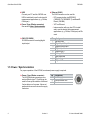
► USB
Connect your PC and the VN7640 over
USB to install and to use the device with
measurement applications (e. g. CANoe,
CANalyzer).
► Power / Sync (Binder connector)
See section Power / Synchronization.
► Ethernet (RJ45)
The RJ45 connector can be used for:
- ECU communication via IEEE802.3
(100BASE-TX/1000BASE-T) and BroadR-
Reach (100 MBit)
- XCP-on-Ethernet
- Interconnection with your host PC to install
and to use the device with measurement
applications (e. g. CANoe, CANalyzer) via Eth-
ernet
► CH5 IO (D-SUB9)
D-SUB9 connector for analog/digital
input/output.
Pin Assignment
1 Analog Input
2 Digital Input/Output 0
3 Digital Input/Output 1
4 Digital Input 0
5 Digital Input 1
6 Analog GND
7 Not connected
8 Digital Output
9 Digital GND
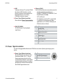
1.5 Power / Synchronization
For proper operation of the VN7640, an external power supply is required.
► Power / Sync (Binder connector)
The VN7640 has two power/sync con-
nectors (Binder type 711) which can be
used for time synchronization of different
Vector devices or for power. It does not
matter which connector is used to supply
the device.
Pin Assignment
1 Power supply
2 Synchronization line
3 Ground
3
1
2

DEUTSCH Kurzanleitung VN7640
© Vector Informatik GmbH Version 1.1 5
1 DEUTSCH
1.1 Installation
Schritt-für-Schritt-Anleitung
Bitte verwenden Sie die Treiber auf der beiliegenden Vector Driver Disk.
1. Führen Sie das Vector Driver Setup im Autostartmenü oder direkt von
\Drivers\Setup.exe aus, bevor das Gerät über USB angeschlossen wird.
Wenn Sie das Gerät bereits angeschlossen haben sollten, erscheint automatisch der Windows
Hardware Wizard für die Treibersuche. Schließen Sie diesen Wizard und starten Sie das Trei-
ber-Setup.
2. Führen Sie die Installation mit Hilfe des Setups durch.
3. Nach erfolgreicher Installation kann das Gerät über USB an den PC angeschlossen werden.
Das Gerät ist nun betriebsbereit.
4. Zur Änderung der Standardeinstellung von Kanalzuweisungen zwischen dem Gerät und einer
Applikationen muss das Konfigurationstool Vector Hardware Config genutzt werden. Das
Tool finden Sie in Windows | Start | Einstellungen | Systemsteuerung | Vector Hardware.
1.2 Weitere Informationen
Verweis
Weitere Informationen zum VN7640 Interface finden Sie im Handbuch auf der Vector Driver Disk
unter \Documentation.
1.3 Zubehör
Verweis
Informationen über das verfügbare Zubehör finden Sie im separaten Zubehörhandbuch auf der
Vector Driver Disk unter \Documentation\Accessories.

1.4 Anschlüsse
Vorderseite
Abbildung 1: Anschlüsse auf der Vorderseite
► CH1...CH4 (D-SUB9)
Das VN7640 verfügt über vier D-SUB9-Stecker. Jeder Stecker ist mit einem entsprechenden Pig-
gyback-Steckplatz verbunden. Die Pinbelegungen der D-SUB9-Stecker sind abhängig von den
eingesetzten Piggybacks. Eine Liste der verfügbaren Piggybacks und deren D-SUB9-Pin-
belegung finden Sie im separaten Zubehörhandbuch auf der Vector Driver Disk unter
\Documentation\Accessories.
Rückseite
Abbildung 2: Anschlüsse auf der USB-Seite
Kurzanleitung VN7640 DEUTSCH
6 Version 1.1 © Vector Informatik GmbH

DEUTSCH Kurzanleitung VN7640
© Vector Informatik GmbH Version 1.1 7
► USB
Verbinden Sie Ihren PC und das VN7640
über diesen USB-Anschluss, um das
Gerät zu installieren und zusammen mit
Messapplikationen (z. B. CANoe,
CANalyzer) nutzen zu können.
► Power / Sync (Binder-Anschluss)
Siehe Abschnitt Power / Synchronisation.
► Ethernet (RJ45)
Der RJ45-Anschluss kann verwendet werden für:
- die Steuergerätekommunikation via
IEEE802.3 (100BASE-TX/1000BASE-T) und
BroadR-Reach (100 MBit)
- XCP-on-Ethernet
- die Verbindung zum Host-PC, um das Gerät
zu installieren und zusammen mit Mess-
applikationen (z. B. CANoe, CANalyzer) via
Ethernet nutzen zu können
► CH5 IO (D-SUB9)
D-SUB9-Stecker für analog/digital
Input/Output.
Pin Belegung
1 Analog Input
2 Digital Input/Output 0
3 Digital Input/Output 1
4 Digital Input 0
5 Digital Input 1
6 Analog GND
7 Nicht verbunden
8 Digital Output
9 Digital GND
1.5 Power / Synchronisation
Für den ordnungsgemäßen Betrieb des VN7640 ist eine externe Spannungsversorgung erfor-
derlich.
► Power / Sync (Binder-Anschluss)
Das VN7640 besitzt zwei Power-/Sync-
Anschlüsse (Binder Typ 711), die zur
Spannungsversorgung oder zur Zeit-
synchronisation mehrerer Vector Geräte
verwendet werden können. Es ist dabei
gleichgültig an welchem Steckverbinder
das Netzteil angeschlossen wird.
Pin Belegung
1 Spannungsversorgung
2 Synchronisationsleitung
3 Masse
3
1
2

Art. 80881
Vector Informatik GmbH
Ingersheimer Straße 24
D-70499 Stuttgart
Copyright © 2018 Vector Informatik GmbH. All rights reserved.
Get More Information
Visit our website for:
► News
► Products
► Demo software
► Support
► Training classes
► Addresses
www.vector.com
-
 1
1
-
 2
2
-
 3
3
-
 4
4
-
 5
5
-
 6
6
-
 7
7
-
 8
8


in anderen Sprachen
- English: Vector VN7640 Quick start guide
Verwandte Papiere
Sonstige Unterlagen
-
 ETAS INCA-FLEXRAY Benutzerhandbuch
-
MSI 7D14 2.0 Bedienungsanleitung
-
ASROCK N73PC-GS - Installationsanleitung
-
ASROCK H61DEL Benutzerhandbuch
-
ASROCK H77 Pro4/MVP Schnellstartanleitung
-
ASROCK H77M Schnellstartanleitung
-
ASROCK Z68MUSB3 Bedienungsanleitung
-
-
