
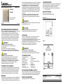
Abb. 1
RAUMBEDIENEINHEIT
BEDIENUNGSANLEITUNG X-AIR-CP-TS
►Deutsch
►English
Weitere Informationen
auf www.trox.de.
Deutsch
A00000051848
BESTIMMUNGSGEMÄSSE VERWENDUNG
Die TROX X-AIRCONTROL Raumbedieneinheit CP-TS (Temperature
Setpoint) ist ein Bediengerät zur benutzerfreundlichen
Temperaturverstellung einer Zone des TROX X-AIRCONTROL
Systems. Die Raumbedieneinheit X-AIR-CP-TS darf ausschließlich
mit durch TROX ausgelieferten oder zugelassenen Komponenten
betrieben werden. Die Montage, Installation und der Betrieb ist nur
unter Berücksichtigung der Montage- und Bedienungsanleitung
zulässig. Weitere Informationen sind auf www.trox.de zu finden.
WARNUNG!
Erhebliche Personen- und Sachschäden.
Die Raumbedieneinheit darf nicht verwendet werden:
►in Ex-Bereichen,
►im Freien ohne Schutz gegen Witterungseinflüsse,
►in Umgebungen, die aufgrund der Umgebungsbedingungen
eine schädigende Wirkung auf das X-AIR-CP-TS haben könnten.
GEFAHR!
Erhebliche Personen- und Sachschäden.
Der elektrische Anschluss darf nur durch eine Elektrofachkraft
erfolgen. Eine Elektrofachkraft ist aufgrund ihrer fachlichen
Ausbildung, Kenntnisse und Erfahrungen sowie Kenntnis der
einschlägigen Normen und Bestimmungen in der Lage, Arbeiten an
elektrischen Anlagen auszuführen und mögliche Gefahren
selbstständig zu erkennen und zu vermeiden.
TRANSPORT UND LAGERUNG
Für den Transport und die Lagerung dürfen die in den technischen
Daten angegebenen Umgebungsbedingungen nicht verletzt werden.
Insbesondere ist das Produkt trocken und gemäß der zulässigen
Temperatur zu lagern und zu transportieren. Unversehrtheit der
Verpackung ist zwingend notwendig zum Schutz des Produktes.
MONTAGE
Die Bedieneinheit ist zur Aufputzmontage in dem zu regelndem Raum
vorgesehen. Die Montagehöhe sollte ca. 1,5m über der Oberkante
des Fertigfußbodens betragen. Naheliegende Wärmequellen, Zugluft
und direkte Sonneneinstrahlung sind zu vermeiden. Die Luftzirkulation
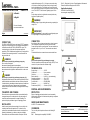
um die Bedieneinheit darf nicht behindert werden. Die beiliegende
Montageschablone Abb. 2 ist zu benutzen. Zur Montage den
Gehäusedeckel lösen. Zur Trennung des Gehäusedeckels vom
Aufputzgerät den Drehknopf in Mittelstellung drehen. Danach kann
der Drehknopf nach vorne abgehoben werden. Die dann sichtbare
Schraube lösen und den Gehäusedeckel entfernen. Das X-AIR-CP-
TS mit 2 Schrauben und einem max. Anzugsmoment von 0.8Nm
befestigen.
Zur Verbindung von Gehäusedeckel und Einbaugerät muss der
Gehäusedeckel aufgesetzt, die Schraube angezogen und der
Drehknopf wieder auf die 50%-Markierung der Achse geschoben
werden.
WARNUNG!
Quetschung. Beim Trennen und Verbinden des Gehäuses besteht
Quetschgefahr für die Finger.
ACHTUNG!
Mechanische Zerstörung. Durch Überschreiten des max.
Anzugsmoments kann das Gehäuse zerstört werden.
ANSCHLUSS
Elektrische Verdrahtungen nur im spannungsfreien Zustand des
Zonenmoduls bzw. der Raumbedieneinheit durchführen.
Die Versorgung für die Raumbedieneinheit X-AIR-CP-TS erfolgt vom
Zonenmodul. Der Anschluss erfolgt mittels Einzeladern an
Schraubklemmen. Die Klemmen dürfen mit max. 1,5 mm² Leitungen
belegt werden. Abb. 1 zeigt die Anschlussdarstellung.
Detailliertere Anschlussinformationen auf www.trox.de.
WARNUNG!
Erhebliche Personen- und Sachschäden.
Das Gerät arbeitet mit Schutzkleinspannung (10V DC).
Der Anschluss an eine abweichende Spannung ist nicht zulässig.
TECHNISCHE DATEN
Versorgungsspannung ............ 10V DC
Anschlüsse .............................. 5 Schraubklemmen
Kabelabmessungen ................. max. 1,5mm²
Relative Feuchte ...................... 0-95% r.H. (nicht kondensierend)
Betriebstemperatur ................... -10/+50°C
zul. Lagertemperatur ................ -20/+60°C
Schutzart .................................. IP30 (EN 60529)
Abmessungen .......................... 84×84×27mm
Potentiometer (IN/OUT) ........... 10 kOhm (10V DC)
ENTSORGUNG UND UMWELTSCHUTZ
Schützen Sie die Umwelt, indem sie die Verpackung und gebrauchte
Produkte umweltgerecht entsorgen. Das Gerät und die Verpackung
müssen gemäß den lokal gültigen Vorschriften entsorgt werden.
SERVICE UND WARTUNG
Die Bedieneinheit X-AIR-CP-2T ist wartungsfrei.
CE-KENNZEICHNUNG
TROX GmbH erklärt hiermit, dass das Produkt in Übereinstimmung
mit den folgenden Richtlinien des Europäischen Parlaments ist:
EMV - Elektromagnetische Verträglichkeit: 2014/30/EU
RoHS - Beschränkung der Verwendung bestimmter gefährlicher
Stoffe: 2011/65/EU
Angewandte Standards
EN 61000-6-2 und EN 61000-6-3
Elektromagnetische Verträglichkeit (EMV).
Abbildungen ____________
67661
TROX GmbH
Heinrich-Trox-Platz
Bedienungsanleitung X-AIR-CP-TS
47504 Neukirchen-Vluyn
www.trox.de
Germany
Doc ID: A00000053961, V1.0, DE/de © TROX GmbH 01/2017
Abb. 2

Fig. 1
ROOM CONTROL PANEL
OPERATING INSTRUCTIONS X-AIR-CP-TS
►Deutsch
►English
For more information
see www.troxtechnik.com.
English
A00000051848
CORRECT USE
The TROX X-AIRCONTROL room control panel CP-TS (Temperature
Setpoint) is a user friendly device to set or change the temperature in
individual zones within the TROX X-AIRCONTROL system. The
control panel must only be used with components supplied or
approved by TROX. Installation and operation have to comply with the
information in the operating instructions. For more information see
www.troxtechnik.com.
WARNING!
Risk of serious personal injury and damage to property.
Do not use the control panel
►in areas with potentially explosive atmospheres.
►outdoors without sufficient protection against the effects of weather.
►in environments that might have a detrimental effect on the control
panel.
DANGER!
Risk of serious personal injury and damage to property. Only
skilled qualified electricians must make electrical connections. Skilled
qualified electricians are individuals who have sufficient professional
or technical training, knowledge and actual experience to enable them
to work on electrical systems, understand any potential hazards
related to the work under consideration, and recognise and avoid any
risks involved.
TRANSPORT AND STORAGE
Ensure the correct environmental conditions (see technical data) for
storage and transport. Store the product in a dry place and do not
exceed the maximum temperature for storage or handling. The
product will only be protected as long as the packaging is intact.
INSTALLATION
Install the control panel (surface mounting) in the room that is to be
controlled. Install the control panel about 1.5 m above the floor
surface. Select an installation location where the control panel is not
affected by disturbances (e.g. radiators, solar gain or draughts).
Ensure that the air can circulate around the control panel. Use the
supplied drill template (see Fig. 2). You have to remove the casing
cover in order to install the control panel. Start by setting the rotary
knob to the middle position. This will allow you to remove the rotary
knob. Loosen the screw under the rotary knob and remove the casing
cover. Fix X-AIR-CP-TS with 2 screws; tightening torque: 0.8 Nm
max.
Put the casing cover back on, tighten the screw and put the rotary
knob back on (middle position).
WARNING!
Crushing. Danger of finger crushing when removing or replacing the
casing cover.
IMPORTANT!
Mechanical destruction. Do not exceed the normal tightening torque
as it may damage the control panel beyond repair.
CONNECTION
Start wiring only after you have made sure that no voltage is present.
The control panel is supplied with power from the zone module.
Connect the single wires to screw terminals. The screw terminals are
designed for wires of up to 1.5 mm². The connections are shown in
Fig. 1.
For detailed information on connections see www.troxtechnik.com.
WARNING!
Risk of serious personal injury and damage to property.
The device operates on protective extra-low voltage (10V DC). Do not
connect it to a power source with a different voltage.
TECHNICAL DATA
Supply voltage ......................... 10 V DC
Connections ............................. 5 screw terminals
Cable size ................................ 1.5 mm² max.
Relative humidity ...................... 0 to 95% r.H. (non-condensing)
Operating temperature ............. -10 to +50°C
Storage temperature: ............... –20 to +60 °C
Protection level ........................ IP30 (EN 60529)
Dimensions .............................. 84×84×27 mm
Potentiometer (IN/OUT) ........... 10 k ohms (10 V DC)
DISPOSAL AND ENVIRONMENTAL
PROTECTION
Dispose of packaging and used products in an environmentally
friendly manner. Dispose of the device and the packing in compliance
with local regulations.
SERVICE AND MAINTENANCE
X-AIR-CP-2T is maintenance-free.
CE MARKING
This is to certify that this product conforms to the following EU
directives:
EMC - Electromagnetic compatibility: 2014/30/EU
RoHS - (Restriction of the Use of Certain Hazardous Substances in
Electronic and Electrical Equipment: 2011/65/EU
Applicable standards
EN 61000-6-2 and EN 61000-6-3
electromagnetic compatibility (EMC).
Illustrations____________
67661
TROX GmbH
Heinrich-Trox-Platz
Operating instructions X-AIR-CP-TS
47504 Neukirchen-Vluyn
www.troxtechnik.com
Germany
Doc ID: A00000053961, V1.0, DE/en © TROX GmbH 01/2017
Fig. 2
-
 1
1
-
 2
2


in anderen Sprachen
- English: Trox X-AIR-CP Installation guide
Verwandte Artikel
-
Trox X-AIR-CP Installationsanleitung
-
-
-
-
-
-
-
-
-