Me AC-10-EX Bedienungsanleitung
- Kategorie
- Türsprechanlagen
- Typ
- Bedienungsanleitung
Dieses Handbuch eignet sich auch für

AERCOM AC-210
AERCOM AC-220
AERCOM AC-10 EX
BETRIEBSANLEITUNG
OPERATING INSTRUCTIONS
MODE D’EMPLOI
GEBRUIKSAANWIJZING

AERCOM | DEUTSCH
2
1
2
1.1
2.1
1.2
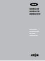
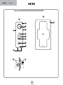
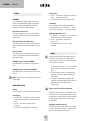
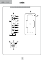
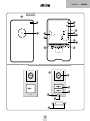
INNENSTATION •INDOOR STATION • BOÎTIER INTÉRIEUR • BINNENSTATION
1.3
1.4
1.5
1.6
1.7
1.8
1.10
1.11
1.12
1.14
1.13
1.9

DEUTSCH | AERCOM
3
3
3.1
3.1
3.3
3.9
3.5
3.6
3.8
3.4
3.2
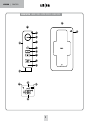
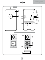
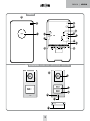
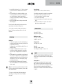
POWERBOX
7“
AUSSENSTATION• OUTDOOR STATION • BOÎTIER EXTÉRIEUR • BUITENSTATION
2
4
4.2
4.3
4.4
4.1
4.5
4.6
3.103.13
3.11
3.12

AERCOM | DEUTSCH
4
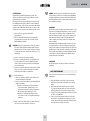
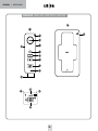
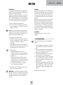
1.2 Lautsprecher
1.3 EIN/AUS Schalter
1.4 Intercomtaste
1.5 Sprechtaste
1.6 Türöffnertaste
1.7 LC-Display
1.8 Mikrofon
1.9 Ladekontakte
1.10 Laut/Leise-Taster
1.11 Empfangsanzeige
1.12 Lautstärkeanzeige
1.13 Akkuanzeige
1.14 Temperaturanzeige
2 Ladeschale
2.1 Power-LED
3 Powerbox
3.1 Power-LED
3.2 Lautsprecher
3.3 Lautsprecherkontakt
3.4 Laut/Leise Klingelton Powerbox
3.5 Code-Taste Familie 1
3.6 Code-Taste Familie 2 (nur bei 2-Familien-Variante vorhanden)
3.8 Laut/Leise Klingelton Außenstation
3.9 Umschaltung Türöffner
3.10 Anschlussterminal
3.11 EIN/AUS Klingelton Powerbox
3.12 EIN/AUS Klingelton Außenstation
3.13 Buchse für 12Volt Betriebsspannung
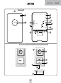
4 Außenstation
4.1 Helligkeitssensor
4.2 Lautsprecher
4.3 Klingeltaster Familie 1
4.4 Klingeltaster Familie 2 (nur bei 2-Familien-Variante vorhanden)
4.5 Gehäuseschrauben
4.6 Mikrofon
MONTAGE
Vor endgültiger Montage sollten Sie die Anlage probehalber in Betrieb
nehmen und testen, ob eine ausreichende Funk-Reichweite vorhanden
ist. Dazu können Sie einfach das Steckernetzteil an die Powerbox
anschließen und die Powerbox ungefähr an der Stelle positionieren, wo
der endgültige Montageort vorgesehen ist.
AerCom Funk-Türsprechanlage Modelle:
AC-210,
AC-220,
AC-10 EX
Vielen Dank für den Kauf dieser Funk-Türsprechanlage von m-e.
Bitte lesen Sie diese Betriebsanleitung sorgfältig durch und bewahren Sie
diese für eine eventuelle spätere Verwendung auf.
LIEFERUMFANG
MODELL AC-210
1x Außenstation
1x Powerbox
1x Innenstation
1x Ladeschale
1x Netzteil für Ladeschale
1x Netzteil für Powerbox
1x Befestigungsmaterial
1x Montage und Betriebsanleitung
1x Bohrschablone für Außenstation
MODELL AC-220
1x Außenstation
1x Powerbox
2x Innenstation
2x Ladeschale
2x Netzteil für Ladeschale
1x Netzteil für Powerbox
1x Befestigungsmaterial
1x Montage und Betriebsanleitung
1x Bohrschablone für Außenstation
MODELL AC-10 EX
1x Innenstation
1x Ladeschale
1x Netzteil für Ladeschale
1x Befestigungsmaterial
1x Montage und Betriebsanleitung
LEGENDE
1 Mobile Innenstation
1.1 Power-LED

DEUTSCH | AERCOM
5
AUSSENSTATION
Die Außenstation ist gemäß IP44 Spritzwasser geschützt, sollte
aber keinem starken Regen ausgesetzt werden. Daher ist ein etwas
geschützter Montageort von Vorteil.
Die Leitung zwischen Powerbox und Außenstation ist an der Powerbox
mit Schraubklemmen angeschlossen. Durch Lösen aller Schraubklem-
men kann die Leitung von der Powerbox getrennt werden. Das Anschlus-
sterminal ist mit den Kabelfarben gekennzeichnet, sie sollten sich aber
trotzdem notieren oder fotografieren, wie die Adern angeschlossen sind.
1) Suchen Sie sich einen geeigneten Standort für die
Außensprechstelle.
2) Bohren Sie anhand der Bohrschablone die Befestigungslöcher
mit einem Durchmesser von 6mm, sowie ein 8mm-Loch für die
Kabeldurchführung in die Wand.
ACHTUNG: Bohren Sie das 8mm-Loch nur an dieser Stelle, wenn Sie
die Powerbox direkt gegenüber der Außensprechstelle montieren.
Andernfalls suchen Sie sich eine geeignete Stelle für die Verlegung
der Leitung und verlegen diese dann bis zur Powerbox (max. 10m
Leitungslänge).
3) Setzen Sie in die 6mm Löcher jeweils einen Dübel.
4) Entfernen Sie die beiden Schrauben (4.5) der Außenstation, um
das vordere Gehäuse-Teil vom unteren Teil abheben zu können
(achten Sie darauf, die Leitung von Lautsprecher und Helligkeits-
sensor nicht abzureißen).
5) Schieben Sie das Kabel der Außenstation durch das 8mm-Loch bzw.
verlegen Sie es bis zur Powerbox und schrauben Sie das hintere
Gehäuseteil mit vier Schrauben an der Wand fest.
6) Namensschild anpassen
1. Nehmen Sie das Namensschild vom vorderen Gehäuseteil ab
(wird nur durch Magneten festgehalten).
2. Entfernen Sie die beiden Schrauben aus dem Namensschild und
klappen es auseinander.
a) Nehmen Sie den Papierstreifen heraus und schreiben
Sie Ihren Namen darauf, alternativ können Sie sich
auch ein Namensschild am PC erstellen und ausdrucken.
Der Papierstreifen hat die Maße 15mm x 70mm.
b) Montieren Sie die Außensprechstelle wieder, indem
Sie die Schritte 6.1 und 6.2 in umgekehrter Reihenfolge
wiederholen.
7) Hängen Sie das vordere Gehäuseteil über das hintere Gehäuseteil
und setzen Sie die beiden Schrauben (4.5) wieder ein.
HINWEIS: Um die Leitung von der Außen-Sprechstelle nicht sichtbar
verlegen zu müssen, bohren Sie das Loch für die Leitungsdurchführung
vorzugsweise direkt hinter der Außensprechstelle durch die Wand (wie
auf der Bohrschablone). Wird die Powerbox direkt gegenüber montiert,
ist der Aufwand am geringsten.
POWERBOX
Die Powerbox ist nur für eine Montage im Innenraum geeignet, sie wird
einfach an einer Schraube aufgehängt. Bohren Sie an einer geeigneten
Stelle ein 6mm Loch in die Wand, stecken einen Dübel hinein und
drehen die Schraube soweit hinein, das der Kopf der Schraube noch ca.
3mm absteht. Dann kann die Powerbox daran aufgehängt werden.
Sollte die Powerbox zu lose hängen, drehen Sie die Schraube etwas
weiter in die Wand.
Das Verbindungskabel zur Außenstation kann von hinten in die Power-
box eingeführt werden, Sie sollten beim Verlegen der Leitung darauf
achten, dass die Leitung an der richtigen Stelle hinter der Powerbox aus
der Wand kommt. Für den Fall, dass die Leitung auf Putz verlegt wurde,
hat die Powerbox auf der Rückseite einen kleinen Kabelkanal, über den
Sie das Kabel in die Powerbox einführen können. Dadurch steht die
Powerbox dann nicht von der Wand ab.
LADESCHALE
Die Ladeschale wird, wie die Powerbox, einfach an einer Schraube
aufgehängt.
ERSTE INBETRIEBNAHME
Laden Sie die mobile Innenstation(en) vor der ersten Inbetriebnahme
vollständig auf.
1. Netzteil für Ladeschale in die Steckdose stecken und mit dem
Hohlstecker an der Ladeschale anschließen. Die rote Power LED
leuchtet.
2. Mobile Innenstation in die Ladeschale legen, die Power-LED
(1.1) zeigt den Ladevorgang durch rotes Leuchten an. Wenn der
Ladevorgang abgeschlossen ist, wechselt die Anzeige auf grün.
3. Schließen Sie die Leitung der Außenstation wieder an die Powerbox
an, falls Sie sie getrennt haben.
4. Stecken Sie das Steckernetzteil der Powerbox in eine Steckdose
und verbinden Sie den Hohlstecker mit der Buchse (3.13) in der
Powerbox. Die Power LED leuchtet nach einigen Sekunden auf und
an der Außenstation ist ein kurzer Ton zu hören.

AERCOM | DEUTSCH
6
MOBILE INNENSTATION
Einschalten
Mit dem Schiebeschalter (1.3) wird die mobile Innenstation EIN oder
AUS geschaltet.
Klingelton einstellen
1. Drücken und halten Sie die -Taste am Laut/Leise-Taster (1.10)
für 5 Sekunden gedrückt, bis die Innenstation Ihren eingestellten
Klingelton abgibt. Lassen Sie die Taste dann los.
2. Durch kurzes Drücken auf die -Taste am Laut/Leise-Taster (1.10)
wird der nächste Klingelton abgespielt.
3. Um den Klingelton zu speichern, drücken Sie einmal kurz auf die
Intercom-Taste (1.4)
Klingellautstärke einstellen
1. Drücken Sie die -Taste am Laut/Leise-Taster (1.10) kurz um die
Lautstärke zu verringern, bzw. die +Taste um die Lautstärke zu erhöhen.
2. Drücken Sie die Intercomtaste (1.4) um die Änderung der Lautstärke
zu speichern.
Gesprächslaustärke einstellen
Mit dem Laut/Leise-Taster können Sie die Gesprächslautstärke
einstellen, während das Gespräch mit der Außenstation geführt wird.
Drücken auf die -Taste verringert die Lautstärke, drücken auf die +Taste
erhöht die Lautstärke.
Temperaturanzeige °C/°F wechseln
1. Drücken und halten Sie die +Taste am Laut/Leise-Taster (1.10) für
5 Sekunden gedrückt, bis die Innenstation einen Ton abgibt. Lassen
Sie die Taste dann los.
2. Durch kurzes Drücken auf die +Taste am Laut/Leise-Taster (1.10)
wird zwischen °C und °F umgeschaltet.
3. Durch Drücken der Intercomtaste (1.4) wird die °-Anzeige dauer-
haft gespeichert.
Codierung
Wenn eine mobile Innenstation dazu gekauft wurde, muss diese erst
auf das System codiert werden. Die AC-210 kann auf max. 4 Innen-
stationen, die AC-220 auf 2 Innenstationen pro Klingeltaster erweitert
werden. Dazu gehen Sie wie folgt vor:
1. Drücken und halten Sie die Code-Taste (3.5 oder 3.6*) für 5
Sekunden, bis die Außenstation einen Bestätigungston abgibt,
lassen Sie die Taste danach los.
5. Schalten Sie die mobile Innenstation mit dem Schalter (1.3) ein,
die Empfangsanzeige (1.11) blinkt erst einige Sekunden. Wenn die
Verbindung hergestellt wurde, zeigt das LC-Display die Temperatur
an und die Empfangsanzeige wird dauerhaft dargestellt.
Die Türsprechanlage ist jetzt einsatzbereit.
EINSTELLUNGEN
POWERBOX
Um die Powerbox zu öffnen, drücken Sie von unten gegen die
Entriegelung und heben Sie das Frontcover vorsichtig nach vorne ab.
Achten Sie dabei darauf, dass die Kabel zwischen Hauptplatine und
Lautsprecher nicht abreißen. Der Lautsprecher ist mit einem Stecker mit
der Hauptplatine verbunden.
Klingeltonlautstärke der Powerbox
Mit dem Potentiometer (3.4) können Sie die Lautstärke des Klingeltons
der Powerbox einstellen. Drehen im Uhrzeigersinn erhöht, drehen gegen
den Uhrzeigersinn vermindert die Lautstärke.
Klingelton- und Gesprächslautstärke der Außenstation
Mit dem Potentiometer (3.8) können Sie die Lautstärke der Außen-
station einstellen. Drehen im Uhrzeigersinn erhöht, drehen gegen den
Uhrzeigersinn vermindert die Lautstärke.
Türöffner-Umschalter
Mit dem Schiebeschalter (3.9) wird eingestellt, ob bei Betätigung des
Türöffners 12V eingeschaltet oder ausgeschaltet wird. Im Normalfall
muss der Schalter nach oben geschaltet sein (vom Terminal weg).
Klingelton der Powerbox EIN/AUS schalten
Mit dem Schiebeschalter (3.11) kann der Klingelton der Powerbox EIN-
bzw. AUS-geschaltet werden.
Klingelton der Außenstation EIN/AUS schalten
Mit dem Schiebeschalter (3.12) kann der Klingelton an der Außenstation
EIN- bzw. AUS-geschaltet werden.
HINWEIS: Der Klingelton an Außenstation und Powerbox ist fest
eingestellt und kann nicht verändert werden.

DEUTSCH | AERCOM
7
An der mobilen Innenstation blinkt zusätzlich der Leuchtrahmen um
die Sprechtaste.
2. Drücken Sie innerhalb einer Minute** einmal kurz auf die Sprech-
taste, um mit dem Besucher sprechen zu können (es dauert ca.
2 Sekunden, bis die Sprechverbindung aufgebaut wurde), im
Display steht „CA“ während das Gespräch aktiv ist.
3. Während die Sprechverbindung aufgebaut ist, können Sie durch
Drücken der Türöffnertaste den Türöffner aktivieren. Die Öffnung
wird optisch und akustisch an der Außeneinheit angezeigt. Falls der
Besucher nicht hinein gelangt ist, können Sie den Türöffner durch
erneutes Drücken der Türöffnertaste wieder aktivieren.
4. Beenden Sie die Sprechverbindung durch kurzes Drücken der
Sprechtaste. Der Leuchtrahmen um die Sprechtaste ist dann wieder
aus und der Hörer befindet sich wieder im Wartebetrieb.
*Hinweis AC-220: Wenn eine der beiden Klingeltasten gedrückt
wurde, ist die andere Klingeltaste für ca. 1 Minute gesperrt, bzw. bis
eine Gespräch aufgebaut und beendet wurde.
**Der Klingelton wird für diese Zeit wiedergegeben. Klingelt der Hörer
nicht mehr, ist es nicht mehr möglich das Gespräch aufzubauen, ohne
das erneut geklingelt wurde.
Intercom-Funktion
(nur innerhalb einer Wohneinheit möglich, nicht wohnungsübergrei-
fend)
Wenn an einen Klingeltaster 2 mobile Innenstationen angelernt
wurden, können Sie von einem Hörer den anderen anrufen.
1. Drücken Sie die Intercomtaste (1.4) an der Innenstation.
2. Die zweite Innenstation klingelt.
3. Drücken Sie an der zweiten Innenstation die Intercomtaste, um das
Gespräch anzunehmen.
4. Drücken Sie an einer der beiden Innenstationen die Intercomtaste,
um die Hörer wieder in den Wartebetrieb zu bringen.
TECHNISCHE DATEN
Frequenz (DECT): 1,8GHz
Reichweite: bis zu 250m (Freifeld)
Mobile Innenstation
Stromversorgung: 3,7V /650mAh LiIon
Standby-Zeit: ca. 24h
2. Drücken und halten Sie an der mobilen Innenstation die Intercom-
taste (1.4) für 5 Sekunden drückt, bis im Display „RE“ angezeigt
wird. Lassen Sie die Taste dann los.
3. Nach erfolgreicher Codierung gibt zuerst die Außenstation einen
Bestätigungston ab und gleich danach die Innenstation. Außerdem
zeigt das Display nach erfolgreicher Codierung die Außentem-
peratur an.
Dieser Vorgang ist für jede Inneneinheit zu wiederholen.
*Bei Modell AC-210 ist nur die Code-Taste 3.5 vorhanden, bei Modell
AC-220 sind beide vorhanden, Die Code-Taste 3.5 ist für den oberen
Klingeltaster, während 3.6 für den unteren Klingeltaster zuständig ist.
Je nachdem, ob Sie eine Innenstation an dem oberen oder unteren
Klingeltaster anlernen wollen, ist die entsprechende Code-Taste zu
benutzen.
Reset der Codierung an der Powerbox
Wird die mobile Innenstation aufgrund eines Defektes getauscht, ist es
notwendig, die Codierung an der Powerbox komplett zu löschen, dazu
führen Sie folgende schritte an der Powerbox durch:
1. Drücken und halten Sie die Code-Taste (3.5 oder 3.6*) für 5
Sekunden, bis die Außenstation einen Bestätigungston abgibt,
lassen Sie die Taste danach los.
2. Drücken Sie 5x kurz auf die Code-Taste (bei jedem Drück hören Sie
einen Ton an der Außenstation, der fünfte Druck wird mit einem
etwas anderen Ton hervorgehoben) und warten Sie für ca. 30
Sekunden (die Power-LED an der Powerbox erlischt kurz, da die
Powerbox neu startet).
3. War an den Klingeltaster eine Innenstation angemeldet, zeigt diese
im Display jetzt „UN“ an.
Der Code ist jetzt gelöscht und die (neue) Innenstation kann wie im
Punkt „Codierung“ (wieder) angemeldet werden.
*Bei der AC 210 ist nur die Code-Taste 3.5 vorhanden, bei der AC 220
sind beide vorhanden, Die Code-Taste 3.5 ist für den oberen Klingelta-
ster, während 3.6 für den unteren Klingeltaster zuständig ist.
BEDIENUNG
Türsprechfunktion
1. Um zu klingeln, drücken Sie auf das Namensschild der Außen-
station, je nach Einstellung klingeln jetzt die Außenstation, die
Powerbox und die mobile Innenstation.*

AERCOM | DEUTSCH
8
Gehen Sie vorsichtig mit dem Produkt um - durch Stöße, Schläge oder
dem Fall aus bereits geringer Höhe wird es beschädigt.
2 JAHRE BESCHRÄNKTE GARANTIE
Es wird für die Dauer von 2 Jahren ab Kaufdatum gewährleistet, dass
dieses Produkt frei von Defekten in den Materialien und in der Ausfüh-
rung ist. Dies trifft nur zu, wenn das Gerät in üblicher Weise benutzt
wird und regelmäßig instand gehalten wird. Die Verpflichtungen dieser
Garantie werden auf die Reparatur oder den Wiedereinbau irgendeines
Teils des Gerätes begrenzt und gelten nur unter der Bedingung, dass
keine unbefugten Veränderungen oder versuchte Reparaturen vorge-
nommen wurden. Ihre gesetzlichen Rechte als Kunde werden in keiner
Weise durch diese Garantie beeinträchtigt.
Bitte beachten Sie!
Es besteht kein Anspruch auf Garantie in u. a. folgenden Fällen:
• Bedienungsfehler
• falsche Codierung/Kanalwahl
• Störungen durch andere Funkanlagen (z.B. Handybetrieb)
• Fremdeingriffe/-wirkungen
• Mechanische Beschädigungen
• Feuchtigkeitsschäden
• Kein Garantie-Nachweis (Kaufbeleg)
Bei Schäden, die durch Nichtbeachten dieser Bedienungsanleitung
verursacht werden, erlischt der Garantieanspruch. Für Folgeschäden
übernehmen wir keine Haftung! Bei Sach- oder Personenschäden, die
durch unsachgemäße Handhabung oder Nichtbeachten der Sicherheits-
hinweise verursacht werden, übernehmen wir keine Haftung. In solchen
Fällen erlischt jeder Garantieanspruch!
Haftungsbeschränkung
Der Hersteller ist nicht für den Verlust oder die Beschädigung irgendwel-
cher Art einschließlich der beiläufigen oder Folgeschäden haftbar, die
direkt oder indirekt aus der Störung dieses Produktes resultieren.
DE
Diese Bedienungsanleitung ist eine Publikation der
m-e GmbH modern-electronics,
An den Kolonaten 37, 26160 Bad Zwischenahn
Diese Bedienungsanleitung entspricht dem technischen Stand bei
Drucklegung. Änderung in Technik und Ausstattung vorbehalten.
Ladeschale
Stromversorgung: 6V DC / 300mA
Powerbox
Stromversorgung: 12 Volt DC / 2000mA
Stromaufnahme Standby: ca. 60mA / ca. 1W
HINWEISE
Unter Einwirkung von starken statischen, elektrischen oder hochfre-
quenten Feldern (Entladungen, Mobiltelefonen, Funkanlagen, Handys,
Mikrowellen) kann es zu Funktionsbeeinträchtigungen der Geräte (des
Gerätes) kommen.
Reinigung und Pflege
Netzbetriebene Geräte vor dem Reinigen vom Netz trennen (Stecker
ziehen). Die Oberfläche des Gehäuses kann mit einem mit Seifenlauge
angefeuchtetem weichen Tuch gereinigt werden. Verwenden Sie keine
Scheuermittel oder Chemikalien. Staubablagerungen an Lüftungs-
schlitzen nur mit einem Pinsel lösen und gegebenenfalls mit einem
Staubsauger absaugen. Die Saugdüse nicht direkt an das Gerät halten.
SICHERHEITSHINWEISE
Bei Schäden, die durch Nichtbeachten dieser Bedienungsanleitung
verursacht werden, erlischt der Garantieanspruch. Für Folgeschäden
übernehmen wir keine Haftung!
Bei Sach- oder Personenschäden, die durch unsachgemäße Handha-
bung oder Nichtbeachten der Sicherheitshinweise verursacht werden,
übernehmen wir keine Haftung. In solchen Fällen erlischt jeder
Garantieanspruch!
Aus Sicherheits- und Zulassungsgründen (CE) ist das eigenmächtige
Umbauen und/oder Verändern des Produkts nicht gestattet.
Zerlegen Sie das Produkt nicht!
Lassen Sie das Verpackungsmaterial nicht achtlos liegen, Plastikfolien/-
tüten, Styroporteile etc. könnten für Kinder zu einem gefährlichen
Spielzeug werden.
Powerbox, Ladeschale, mobile Inneneinheit und Netzteile sind nur
für trockene Räume geeignet (keine Badezimmer o.ä. Feuchträume).
Vermeiden Sie ein Feucht- oder Nasswerden.

DEUTSCH | AERCOM
9

AERCOM | ENGLISH
10
1
2
1.1
2.1
1.2
INNENSTATION •INDOOR STATION • BOÎTIER INTÉRIEUR • BINNENSTATION
1.3
1.4
1.5
1.6
1.7
1.8
1.10
1.11
1.12
1.14
1.13
1.9

ENGLISH | AERCOM
11
3
3.1
3.1
3.3
3.9
3.5
3.6
3.8
3.4
3.2
POWERBOX
7“
AUSSENSTATION• OUTDOOR STATION • BOÎTIER EXTÉRIEUR • BUITENSTATION
3.103.13
3.11
3.12
2
4
4.2
4.3
4.4
4.1
4.5
4.6

AERCOM | ENGLISH
12
AerCom wireless intercom system models:
AC-210
AC-220
AC-10 EX
Thank you for purchasing this wireless intercom system from m-e.
Please read these operating instructions carefully and retain the
instructions for any later use.
SCOPE OF DELIVERY
MODELL AC-210
1x Outdoor station
1x Power box
1x Indoor station
1x Charging cradle
1x Mains power supply for charging cradle
1x Mains power supply for power box
1x Mounting material
1x Assembly and operating instructions
1x Drilling template for outdoor station
MODELL AC-220
1x Outdoor station
1x Power box
2x Indoor station
2x Charging cradle
2x Mains power supply for charging cradle
1x Mains power supply for power box
1x Mounting material
1x Assembly and operating instructions
1x Drilling template for outdoor station
MODELL AC-10 EX
1x Indoor station
1x Charging cradle
1x Mains power supply for charging cradle
1x Mounting material
1x Assembly and operating instructions
KEY
1 Mobile indoor station
1.1 Power-LED
1.2 Loudspeaker
1.3 ON/OFF switch
1.4 Intercom button
1.5 Talk button
1.6 Door release button
1.7 LC display
1.8 Microphone
1.9 Charging contacts
1.10 Volume button
1.11 Reception indicator
1.12 Volume indicator
1.13 Storage battery indicator
1.14 Temperature indicator
2 Charging cradle
2.1 Power-LED
3 Power box
3.1 Power-LED
3.2 Loudspeaker
3.3 Loudspeaker contact
3.4 Ringer volume power box
3.5 Code button Family 1
3.6 Code button Family 2 (only on the 2-family version)
3.8 Ringer volume on outdoor station
3.9 Switch for door opener
3.10 Connection terminal
3.11 ON/OFF ringer on power box
3.12 ON/OFF ringer on outdoor station
3.13 Socket for 12 volt operating voltage
4 Outdoor station
4.1 Brightness sensor
4.2 Loudspeaker
4.3 Ringer button Family 1
4.4 Ringer button Family 2 (only on the 2-family version)
4.5 Casing screws
4.6 Microphone
ASSEMBLY
Please trial the system before final assembly and test whether there
is sufficient wireless range. To do this simply connect the mains power
supply to the power box and position the power box at approximately the
location where you plan the final assembly.

ENGLISH | AERCOM
13
OUTDOOR STATION
The outdoor station is splash-proof in accordance with IP44 but should
not be exposed to heavy rain. Thus a somewhat protected assembly
location is advantageous.
The wire between the power box and the outdoor station is connected
with screw terminals. The wire can be disconnected from the power box
by releasing all the screw terminals. The connection terminal is marked
with the cable colours but you should still note or photograph how the
wires are connected.
1) Find a suitable location for the outdoor intercom unit.
2) Drill the mounting holes with a diameter of 6 mm using the drilling
template and also drill an 8 mm hole to insert the cables through
the wall.
CAUTION: Only drill the 8 mm hole here if you are mounting the
power box exactly opposite the outdoor intercom unit. Otherwise find
a suitable location to lay the cable and then lay it to the power box
(maximum wire length 10 m).
3) Place a dowel in each of the 6 mm holes.
4) Remove both the screws (4.5) from the outdoor station in order
to be able to lift the front casing section from the lower section
(please ensure that the wire for the loudspeaker and brightness
sensor is not ripped out).
5) Push the cable from the outdoor station through the 8 mm hole
or lay it to the power box and screw the back casing section to the
wall with four screws.
6) Adapt nameplate
1. Remove the nameplate from the front casing section (it is held
only by magnets).
2. Remove both the screws from the nameplate and open it up.
a) Remove the strip of paper and write your name on it.
You can also make a nameplate on your PC and print it out.
The dimensions of the paper strip are 15mm x 70mm.
b) Re-mount the outdoor speaker unit by repeating the steps
6.1 and 6.2 in reverse order.
7) Hang the front casing section over the back casing section and
replace the two screws (4.5).
NOTE: In order not to have to lay the wire from the outdoor speaker
unit visibly please drill the hole for the wire penetration through the
wall directly behind the outdoor speaker unit where possible (as shown
on the drilling template). This is easiest if the power box is mounted
directly opposite.
POWER BOX
The power box is only suitable for indoor assembly and is simply hung
on a screw. Drill a 6 mm hole in a suitable position of the wall, insert a
dowel and insert the screw until the head protrudes by approximately 3
mm. The power box then hangs on the screw.
If the power box is too loose, please turn the screw a little further into
the wall.
The connection cable to the outdoor station can be fed into the power
box from the back. When laying the wire please ensure that the wire
comes out of the wall at the right position behind the power box. If
the wire was laid on the plaster then the power box has a small cable
channel on the back, through which you can lead the cable into the
power box. The power box then lies flush against the wall.
CHARGING CRADLE
The charging cradle is simply hung on a screw, like the power box.
INITIAL OPERATION
Charge the mobile indoor station(s) completely before initial operation.
1. Insert the mains power supply for the charging cradle into the
socket and connect using the hollow plug on the charging cradle.
The red power LED will light up.
2. Insert the mobile Indoor station into the charging cradle, the Power
LED (1.1) will indicate the charging process by lighting red. When
the charging process is complete the LED colour will turn to green.
3. Re-connect the wire from the outdoor station to the power box if
you have detached it.
4. Plug the mains power supply for the power box into a socket and
connect the hollow plug with the socket (3.13) in the power box.
The power LED will light after a few seconds and a short tone will
sound on the outdoor station.
5. Switch the mobile indoor station on using the switch (1.3), the
reception indicator (1.11) will flash for a few seconds. Once the
connection is made the LC display will show the temperature and
the reception indicator will be constant.
The intercom is now ready for use.

AERCOM | ENGLISH
14
SETTINGS
POWER BOX
To open the power box press against the latch from below and lift
the front cover up and forwards with care. Make sure that the cables
between the main board and the loudspeaker are not broken. The
loudspeaker is connected to the main board with a plug.
Ringer volume on the power box
You can use the potentiometer (3.4) to set the volume on the ringer
for the power box. Turn clockwise to increase and turn anti-clockwise to
reduce the volume.
Ringer and call volume on the outdoor station
You can use the potentiometer (3.8) to set the volume on the outdoor
station. Turn clockwise to increase and turn anti-clockwise to reduce the
volume.
Door opener switch
Use the slider switch (3.9) to set whether 12V activation of the door
opener is on or off. Normally the switch should be switched upwards
(away from the terminal).
Switching the ringer on the power box ON/OFF
Use the slider switch (3.11) to switch the ringer on the power box ON
or OFF.
Switching the ringer on the outdoor station ON/OFF
Use the slider switch (3.12) to switch the ringer on the outdoor station
ON or OFF.
NOTE: The ringer on the outdoor station and the power box is fixed and
cannot be changed.
MOBILE INDOOR STATION
Switch on
Use the slider switch (1.3) to switch the mobile Indoor station ON or OFF.
Set the ring tone
1. Press and hold the ‘ – ‘ volume button (1.10) for five seconds until
the indoor station sounds with the set ring tone. Then release the
button.
2. Press the ‘ – ‘ volume button (1.10) briefly to hear the
next ring tone.
3. Press briefly on the intercom button (1.4) to set the ring tone.
Set ringer volume
1. Press the ‘ – ‘ volume button (1.10) briefly to decrease the volume
and the ‘ + ‘ button to increase the volume.
2. Press the intercom button (1.4) to save the change in volume.
Set call volume
Use the volume button to set the call volume while carrying out a
conversation with the outdoor station. Pressing on the ‘ – ‘ button de-
creases the volume and pressing the ‘ + ‘ button increases the volume.
Switch temperature indicator °C/°F
1. Press and hold the ‘ + ‘ volume button (1.10) for five seconds until
the indoor station emits a tone. Then release the button.
2. Press the ‘ + ‘ volume button (1.10) briefly to switch
between °C and °F.
3. Press the intercom button (1.4) to save the – ° display
permanently.
CODING
If you have purchased a mobile indoor station with your system then
this needs to be coded to the system. AC-210 can be expanded to a
total of 4 mobile indoor stations, AC-220 to 2 mobile indoor stations for
each ringer button. Proceed as follows:
1. Press and hold the code button (3.5 or 3.6*) for five seconds until
the outdoor station emits a confirmation tone. Then release the
button.
2. Press and hold the intercom button (1.4) on the mobile indoor
station for five seconds until ‘RE’ appears on the display. Then
release the button.
3. Once coding is successful the outdoor station will first emit a
confirmation tone, followed immediately by the indoor station. The
display will also show the outdoor temperature after
coding is successful.
This process must be repeated for each indoor unit.
*Model AC-210 only has the code button 3.5, while model AC-220 has
both; code button 3.5 is for the upper ringer button while 3.6 is for the
lower ringer button. The relevant code button should be used depending
on whether you wish to configure an indoor station on the upper or
lower ringer button.
Resetting the coding on the power box
If the mobile Indoor station is exchanged because of a defect, it will be
necessary to completely delete the coding on the power box. To do this
please carry out the following steps on the power box:

ENGLISH | AERCOM
1515
1. Press and hold the code button (3.5 or 3.6*) for five seconds until
the outdoor station emits a confirmation tone. Then release the
button.
2. Press 5 times briefly on the code button (you will hear a tone at
the outdoor station the first four times and a somewhat different
tone on the fifth depression) and wait for approximately 30
seconds (the power LED on the power box will go out briefly while
the power box restarts).
3. If an indoor station was registered on the ringer button then this
will now display ‘UN’.
The code has now been deleted and the (new) indoor station can be
registered (again) as described in the ‘coding’ section.
*AC 210 only has the code button 3.5 while AC-220 has both; code
button 3.5 is for the upper ringer button while 3.6 is for the lower
ringer button.
OPERATION
Talk function
1. To call press the nameplate on the outdoor station. Depending on
the settings, this will cause the outdoor station, the power box and
the mobile indoor station to ring. *
The illuminated frame around the talk button will also flash on the
mobile indoor station.
2. Press briefly on the talk button within one minute** in order to
speak to the visitor (it will be approximately 2 seconds until the
connection is made). The display will show ‘CA’ while the call is
active.
3. You can activate the door opener with the door release button whi-
le the connection is established. The door opening will be indicated
optically and acoustically on the outdoor unit. If the visitor has not
entered then the door opener can be activated again by pressing
the door release button again.
4. End the call by pressing the talk button briefly. The illuminated
frame around the talk button is then off and the listening function
is back on standby.
*Note AC-220: if one of the two ringer buttons has been pressed then
the other ringer button is blocked for approximately 1 minute or until a
call is connected and ended.
**The ring tone sounds for this time. If the listening function has
stopped ringing, it is no longer possible to connect a call without
ringing again.
Intercom function
(only possible within one residence, not between residences)
If 2 mobile indoor stations have been configured on one ringer button
then it is possible to call from one listening unit to the other.
1. Press the intercom button (1.4) on the indoor station.
2. The second indoor station will ring.
3. Press the intercom button on the second indoor station to accept
the call.
4. Press the intercom button on one of the two indoor stations to
place the listener unit back to standby.
TECHNICAL DATA
Frequency (DECT): 1.8GHz
Range: up to 250m (open space)
Mobile indoor station
Power supply: 3.7V /650mAh LiIon
Standby time: approx. 24h
Charging cradle
Power supply: 6V DC / 300mA
Power box
Power supply: 12 volt DC / 2000mA
Power consumption on standby: ca. 60mA / ca. 1W
NOTES
Strong static, electrical or high frequency fields (discharges, mobile
telephones, radio systems, and microwaves) can cause the appliance(s)
to malfunction.
Cleaning and care
Disconnect mains-powered appliances before cleaning (remove the
plug). The surface of the casing can be cleaned using a soft cloth
dampened in a soap solution. Do not use scouring agents or chemicals.
Release collected dust from ventilation slits using a brush and a
vacuum cleaner if necessary. Do not hold the vacuum nozzle directly on
the appliance.

AERCOM | ENGLISH
1616
quential damage. We do not accept liability for damage to property
or persons caused by inappropriate handling or non-adherence to the
safety notes. No claims can be made on the guarantee in such cases.
Liability limitations
The manufacturer is not liable for the loss or damage of any kind,
including incidental or consequential damage that results directly or
indirectly from the defect in this product.
GB
These operating instructions are a publication of
m-e GmbH modern-electronics,
An den Kolonaten 37,
26160 Bad Zwischenahn
These operating instructions conform to the technical status at the time
of printing. Subject to changes in technology and equipment.
SAFETY NOTES
The guarantee lapses for damage caused by non-adherence to these ope-
rating instructions. We do not accept liability for consequential damage.
We do not accept liability in the event of damage to property or persons
that is caused by inappropriate use or non-adherence to the safety notes.
Any guarantee lapses in such cases.
Unauthorised conversion and/or modification of the product are not
permitted for reasons of safety and certification (CE).
Do not dismantle the product!
Do not leave the packaging materials lying around unattended. Plastic
foil/bags, polystyrene sections etc. could be a dangerous toy for a child.
Power box, charging cradle, mobile indoor unit and mains power unit are
only suitable for dry rooms (no bathrooms or damp rooms). Avoid letting
the units become wet or damp.
Handle the product carefully – it will be damaged by shocks, impacts or
a fall from even a small height.
2-YEAR LIMITED GUARANTEE
We guarantee for a period of 2 years from the date of purchase that
this product will be free of defects in its materials or design. This is
only valid if the appliance is used in the usual manner and is regularly
maintained. The obligations in this guarantee are limited to the repair or
replacement of any part of the appliance and are only valid given that
no unauthorised modifications or attempted repairs have been carried
out. Your statutory rights as a customer are not restricted in any way by
this guarantee.
Please note:
No claim can be made under the guarantee in the following circum-
stances:
• Operating errors
• Incorrect coding / channel choice
• Defects caused by other radio systems (e.g. mobile phone operation)
• Interference or impact by a third party
• Mechanical damage
• Moisture damage
• Lack of proof of guarantee (purchase receipt)
The guarantee is void in the event of damage caused by non-adherence
to these operating instructions. We do not accept liability for conse-

ENGLISH | AERCOM
1717

AERCOM | FRANÇAIS
18
1
2
1.1
2.1
1.2
INNENSTATION •INDOOR STATION • BOÎTIER INTÉRIEUR • BINNENSTATION
1.3
1.4
1.5
1.6
1.7
1.8
1.10
1.11
1.12
1.14
1.13
1.9

FRANÇAIS | AERCOM
19
3
3.1
3.1
3.3
3.9
3.5
3.6
3.8
3.4
3.2
POWERBOX
7“
AUSSENSTATION• OUTDOOR STATION • BOÎTIER EXTÉRIEUR • BUITENSTATION
3.103.13
3.11
3.12
2
4
4.2
4.3
4.4
4.1
4.5
4.6

AERCOM | FRANÇAIS
20
Portier électronique sans fil AerCom, modèles :
AC-210
AC-220
AC-10 EX
Nous vous remercions de votre achat de ce portier électronique sans fil
de m-e.
Veuillez lire attentivement la présente notice d’emploi et la conserver
pour vous y référer ultérieurement le cas échéant.
CONTENU DE LA LIVRAISON
MODELE AC-210
1x module extérieur
1x Powerbox
1x module intérieur
1x chargeur
1x bloc d‘alimentation pour le chargeur
1x bloc d‘alimentation pour le module Powerbox
1x matériel de fixation
1x notice de montage et d‘emploi
1x gabarit de perçage pour le module extérieur
MODELE AC-220
1x module extérieur
1x Powerbox
2x module intérieur
2x chargeur
2x bloc d‘alimentation pour le chargeur
1x bloc d‘alimentation pour le module Powerbox
1x matériel de fixation
1x notice de montage et d‘emploi
1x gabarit de perçage pour le module extérieur
MODELE AC-10 EX
1x module intérieur
1x chargeur
1x bloc d‘alimentation pour le chargeur
1x matériel de fixation
1x notice de montage et d‘emploi
LEGENDE
1 Module intérieur mobile
1.1 DEL d‘alimentation
1.2 Haut-parleur
1.3 Interrupteur MARCHE/ARRET
1.4 Touche Intercom
1.5 Touche d‘interphone
1.6 Touche d‘ouverture de porte
1.7 Ecran LCD
1.8 Microphone
1.9 Contacts de charge
1.10 Bouton de volume
1.11 Témoin de réception
1.12 Affichage du volume
1.13 Affichage de l‘état de charge
1.14 Affichage de la température
2 Chargeur
2.1 DEL d‘alimentation
3 Powerbox
3.1 DEL d‘alimentation
3.2 Haut-parleur
3.3 Contact de haut-parleur
3.4 Volume de carillon Powerbox
3.5 Touche de Code famille 1
3.6 Touche de Code famille 2 (disponible uniquement sur le modèle
pour 2 familles)
3.8 Volume de carillon du module extérieur
3.9 Commutation de la gâche électrique
3.10 Bornier de raccordement
3.11 MARCHE/ARRET du carillon Powerbox
3.12 MARCHE/ARRET du carillon du module extérieur
3.13 Connecteur femelle pour la tension de service 12V
4 Module extérieur
4.1 Capteur de luminosité
4.2 Haut-parleur
4.3 Bouton de sonnette famille 1
4.4 Bouton de sonnette famille 2 (disponible uniquement sur le
modèle pour 2 familles)
4.5 Vis du boîtier
4.6 Microphone
MONTAGE
Nous vous recommandons de mettre l‘installation en service et de la
tester avant le montage définitif, afin de vous assurer que la portée
radio est suffisante. A cet effet, il vous suffit de brancher le bloc
d‘alimentation à fiches au module Powerbox et de positionner celui-ci
approximativement à l‘endroit prévu pour le montage définitif.
20
Seite wird geladen ...
Seite wird geladen ...
Seite wird geladen ...
Seite wird geladen ...
Seite wird geladen ...
Seite wird geladen ...
Seite wird geladen ...
Seite wird geladen ...
Seite wird geladen ...
Seite wird geladen ...
Seite wird geladen ...
Seite wird geladen ...
Seite wird geladen ...
Seite wird geladen ...
Seite wird geladen ...
Seite wird geladen ...
-
 1
1
-
 2
2
-
 3
3
-
 4
4
-
 5
5
-
 6
6
-
 7
7
-
 8
8
-
 9
9
-
 10
10
-
 11
11
-
 12
12
-
 13
13
-
 14
14
-
 15
15
-
 16
16
-
 17
17
-
 18
18
-
 19
19
-
 20
20
-
 21
21
-
 22
22
-
 23
23
-
 24
24
-
 25
25
-
 26
26
-
 27
27
-
 28
28
-
 29
29
-
 30
30
-
 31
31
-
 32
32
-
 33
33
-
 34
34
-
 35
35
-
 36
36


Me AC-10-EX Bedienungsanleitung
- Kategorie
- Türsprechanlagen
- Typ
- Bedienungsanleitung
- Dieses Handbuch eignet sich auch für
in anderen Sprachen
- English: Me AC-10-EX Operating instructions
- français: Me AC-10-EX Mode d'emploi
- Nederlands: Me AC-10-EX Handleiding
Verwandte Artikel
-
Me ADF610 Bedienungsanleitung
-
-
-
m-e VISTA DOOR VDV-B90 Bedienungsanleitung
-
-
-
-
-
Me ADV-264 Bedienungsanleitung
-