
Steckernetzteil
- Ausgangsspannung
- Ausgangsleistung
- Länge des Anschlusskabels
Verbindungskabel
- Länge
39 V
I
nenn
= 150 mA
3 m
ca. 0,3 m
Technische Daten
Identnr. 1101913
Änderung und Irrtum vorbehalten.
Printed in Germany
1082
AGFEO GmbH & Co. KG
Gaswerkstr. 8
D-33647 Bielefeld
Internet: http://www.agfeo.de
Die auf dem Produkt angebrachte durchkreuzte Mülltonne bedeutet, dass das Produkt zur
Gruppe der Elektro- und Elektronikgeräte gehört. In diesem Zusammenhang weist die
europäische Regelung Sie an, Ihre gebrauchten Geräte
- den Verkaufsstellen im Falle des Kaufs eines gleichwertigen Geräts
- den örtlich Ihnen zur Verfügung gestellten Sammelstellen (Wertstoffhof,
Sortierte Sammlung usw.)
zuzuführen.
So beteiligen Sie sich an der Wiederverwendung und der Valorisierung von Elektrik- und
Elektronik-Altgeräten, die andernfalls negative Auswirkungen auf die Umwelt und die
menschliche Gesundheit haben könnten.
Steckernetzteil STE 30/
ST 40/ STE 40
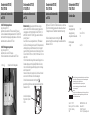
Anschluss des Steckernetzteils
am STE 30
Steckernetzteil STE 30/
ST 40/ STE 40
Ihre STE 30 ist direkt angeschlossen
(vergl. Anleitung STE 30):
Das Netzteil kann sowohl die STE 30 als auch das ST 30 speisen.
Tauschen Sie dazu das Verbindungskabel zwischen ST 30 und STE 30
durch das dem Netzteil beigelegte 6 adrige Kabel aus. Schließen Sie
das Netzteil an der Aux-Buchse der STE 30 an.
Ihre STE 30 ist abgesetzt angeschlossen
(vergl. Anleitung STE 30):
Das Netzteil kann nur eine STE 30 speisen.
Schließen Sie das Netzteil an der Aux-Buchse der STE 30 an.
interner S
0
mitgeliefertes Verbindungskabel
Anschluss des Steckernetzteils
am ST 40
Bitte beachten Sie, dass Sie aufgrund der höheren Leistungs-
aufnahme der AGFEO ST40 und der vorliegenden, physikalischen
Leistungsgrenze der im Markt befindlichen AS 40P (P400-1), AS
4000 (P400-1) und AS 100 IT (P400 IT) ggfs. zusätzliche Netzteile
einsetzen müssen !
Da ein ST40 eine max. Leistungsaufnahme von 1,7 Watt aufweist
(alle LEDs an, A-Modul 40 gesteckt, aktiver Ruf, Ruflautstärke max.)
und die Absicherung eines S0-Moduls 440 immer pro Doppelport
passiert (4,5 Watt), ist diese Grenze bei einer Belastung von 2 Stück
ST40 und 1 Stück ST30 (P max. 1,3 Watt) im "Worst Case Fall" schon
überschritten.
Im Fehlerfall würde die Anlage für den relevanten Doppelport eine
Schutzabschaltung vornehmen (Systels/ISDN Bus ohne Funktion,
nach einem Reset der Anlage wird der Doppelport von der Anlage
wieder freigeschaltet) !
In dieser beschriebenen Konstellation (o.ä.) sollten Sie ein Netzteil
vorsehen um den "Worst Case Fall" damit abzufangen !
Schließen Sie das Netzteil an der mit dem Symbol
gekennzeichneten Buchse an und verlegen Sie das Kabel durch den
Kabelkanal im ST 40.
S0-TK
Modulslot 1
Modulslot 2
Anschluss für optionales
Netzteil oder optionale
STE 40
Steckernetzteil STE 30/
ST 40/ STE 40
Anschluss des Steckernetzteils
am STE 40
Wenn Sie eine STE 40 an Ihrem ST 40 betreiben wollen, so muß diese
STE 40 mit einem Netzteil gespeist werden. Jede weitere an diesem
ST 40 angeschlossene STE 40 wird durch das Netzteil mitversorgt.
Schließen Sie das Netzteil an der mit dem Symbol
gekennzeichneten Buchse an und verlegen Sie das Kabel durch den
Kabelkanal im STE 40.
Steckernetzteil STE 30/
ST 40/ STE 40

39 V
I
nenn
= 150 mA
3 m
ca. 0,3 m
Specification
The crossed out wheeled bin on the product means that this belongs to the group of
Electro- and electronic apparatus.
In this context you are directed by the European regulation to dispose of used apparatus
- at the point of buying an item of equal proportion / value
- at the local available collection point for disposal
With this you will participate in the reuse of material and valorisation of disused electric-
and electronic apparatus, which otherwise could be a health hazard and be negative to the
environment.
Plug In Power Supply
STE 30/ ST 40/ STE 40
Plug In Power Supply
- Output Voltage
- Output Power
- Cable length
Interconnection Cable
- Length
Connection of Power Supply Unit
to STE 40
Plug In Power Supply
STE 30/ ST 40/ STE 40
Should you want to operate an STE 40 on your ST 40, then it will
become necessary to connect a seperate power supply unit to the STE
40. Any additional STE 40 which is connected to the ST 40 will be
powered by the same power supply.
Connect the power supply to the socket marked
and guide the cable through the cable channel of the STE 40.
Connection of Power Supply Unit
to ST40
S0-TK
Modulslot 1
Modulslot 2
Connecton for optional
power supply or
optional STE 40
Plug In Power Supply
STE 30/ ST 40/ STE 40
Please note: That due to a higher power consumption of the AGFEO
ST 40 and the limited capacity of the systems already on the market
such as the AS 40P (P400-1), AS 4000 (P400-1) und AS 100 IT (P400
IT) you may require an additional power supply units. The ST40 will
have a max. power consumption of 1.7 Watt when under full load,
like all LED’s lit, optional answering machine module A-40 installed
and the phone is ringing at full volume. The max. output for a S0 440
module is 4.5 Watt for each two ports combined. This would mean
that in the worst case scenario two ST 40’s and one ST 30 (P max.
1.3 Watt) would already exceed the maximum limit set. This could
activate the overload protection circuit and shut down the power
supply of the relevant combined ports. (System Phones are none
functional / S0 bus no power. Power will be restored after system
reset) In such cases it is suggested to connect an external power
supply to the ISDN bus to avoid such eventualities.
Please connect the RJ plug of the power supply to the socket marked
with this symbol and guide the cable through the cable channel of
the ST 40.
Connection of Power Supply to
STE 30
Plug In Power Supply
STE 30/ ST 40/ STE 40
Internal S
0
Supplied connection cable
STE 30 with Phone
(see also Manual STE 30):
The plug in power supply unit will power both the STE30 and ST 30.
Please replace the cable connecting the ST30 and STE 30 with the 6
wire cable enclosed with the power supply. Connect the RJ plug of the
power supply to the AUX socket of the STE 30.
STE 30 as Stand-Alone Unit
(see also Manual STE 30):
The plug in power supply unit will power only one STE 30. Connect the
RJ plug of the power supply to the AUX socket of the STE 30.
-
 1
1
-
 2
2


AGFEO Netzteil ST 40 IP Installationsanleitung
- Typ
- Installationsanleitung
- Dieses Handbuch eignet sich auch für
in anderen Sprachen
Verwandte Artikel
-
AGFEO Netzteil STE 30 Installationsanleitung
-
-
-
AGFEO ST 40 Bedienungsanleitung
-
-
-
-
-
-