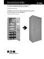
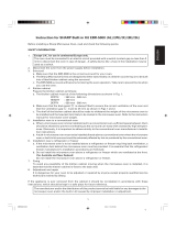
Eaton ZB-S Series Installation Instructions Manual
- Typ
- Installation Instructions Manual

Einbauanleitung Zentralbatterie-System ZB-S
in elektrische Betriebsräume Typ EBR-S
Zielgruppe: Elektrofachkraft
Installation instructions: ZB-S central battery system
in electrical service rooms EBR-S
Target group: Qualified electrician
Elektrische Betriebsräume Typ EBR-S
Electrical service rooms of type EBR-S

2
Einbauanleitung Zentralbatterie-System ZB-S in elektrische Betriebsräume Typ EBR-S 40071860238 (A) August 2014 www.ceag.de
Inhalt / Content
Inhalt
Sicherheitshinweise. . . . . . . . . . . . . . . . . . . . . . . . 2
Einbau ZB-S 2C3, CG100, CG 102 und CG 104 in
elektrischen Betriebsraum EBR-S-1800 .......3
Einbau ZB-S 18C3, 10C3 und CG200 in
elektrischen Betriebsraum EBR-S-1800 .......3
Einbau ZB-S 26, 18, 18C6, 10C6 in
elektrischen Betriebsraum EBR-S-2050 .......4
Technische Daten .......................4-5
Maximale Anzahl von Kabelschotts ............5
Montage Abfangschiene Leitungseinführung ZB-S
mit 600 mm Schranktiefe ..................6
Montage Abfangschiene Leitungseinführung ZB-S
mit 400 mm Schranktiefe ..................6
WICHTIGE HINWEISE
Vor Beginn der Montage sind folgende Montage- und
Bedienungsanleitungen aufmerksam zu lesen:
Montage- und Bedienungsanleitung „Elektrischer
Betriebsraum Priorack ELT EBR“ und
„Einbauanleitung Zentralbatterie-System ZB-S in elektri-
sche Betriebsräume Typ EBR-S“
ACHTUNG
Eine technische Belüftung der elektrischen Betriebsräume
ist zwingend erforderlich und bauseitig zu installieren. Der
notwendige Luftvolumenstrom/Wärmeverlustleistung ist
der Tabelle 1 zu entnehmen.
ACHTUNG
Um Schrauben in das Brandschutzmaterial einschrauben
zu können, müssen die Löcher hierfür vorgebohrt werden.
Bohrlochtiefe: max. 25 mm, Schraubenlänge: max. 25
mm.
Content
Safety notes .............................2
Installation of ZB-S 2C3, CG100, CG 102 and CG
104 in the EBR-S-1800 electrical service room ..7
Installation of ZB-S 18C3, 10C3 and CG200 in the
EBR-S-1800 electrical service room ..........7
Installation of ZB-S 26, 18, 18C6, 10C6 in the
EBR-S-2050 electrical service room ..........8
Technical Data ..........................8-9
Maximum number of cable sealings ...........9
Assembling the stop rail for ZB-S cable infeed
with 600 mm cabinet depth ...............10
Assembling the stop rail for ZB-S cable infeed
with 400 mm cabinet depth ...............10
IMPORTANT
Before commencing installation, the following installation
and operating instructions should be read carefully:
„Priorack ELT EBR Electrical Service Room“ and
„Installation Instructions: ZB-S Central Battery System
in Electrical Service Rooms of Type EBR-S“
CAUTION
Technical ventilation of the electrical service rooms is
mandatory and must be installed on-site. See Table 1 for
the requisite airflow/heat loss rate.
CAUTION
Holes must be pre-drilled for fastening screws into the
fire protection material. Drill hole depth: max. 25 mm,
screw length: max. 25 mm.
D
GB

3
Einbau ZB-S 2C3, CG100, CG 102 und CG 104 in elektrischen Betriebsraum EBR-S-1800
Einbauanleitung Zentralbatterie-System ZB-S in elektrische Betriebsräume Typ EBR-S 40071860238 (A) August 2014 www.ceag.de
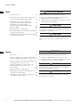
Einbau ZB-S 2C3,
CG100, CG 102 und
CG 104 in elektri-
schen Betriebsraum
EBR-S-1800
1. Untergestell für ELT
Räume 40071360410
mit der Rückwand des
Raumes verschrauben.
2. Anlage aufstellen und
mit der Rückwand des
Raumes verschrauben.
ACHTUNG
Um Schrauben in das
Brandschutzmaterial ein-
schrauben zu können,
müssen die Löcher hier-
für vorgebohrt werden.
Bohrlochtiefe: max. 25
mm, Schraubenlänge:
max. 25 mm.
3. Technische Belüftung
montieren (siehe
Montage- und Bedienungsanleitung ELEKTRISCHER
BETRIEBSRAUM PRIORACK-Elt EBR)
4. Leitungen einführen.
5. Anlage gemäß CEAG Anleitung ZB-S anschließen und
in Betrieb nehmen.
Einbau ZB-S 18C3, 10C3 und CG200 in
elektrischen Betriebsraum EBR-S-1800
1. Anlage aufstellen und mit der Rückwand des Raumes
verschrauben.
ACHTUNG
Um Schrauben in das Brandschutzmaterial einschrauben
zu können, müssen die Löcher hierfür vorgebohrt werden.
Bohrlochtiefe: max. 25 mm, Schraubenlänge: max. 25
mm.
2. Technische Belüftung montieren (siehe Montage- und
Bedienungsanleitung ELEKTRISCHER BETRIEBSRAUM
PRIORACK-Elt EBR)
3. Leitungen einführen.
4. Anlage gemäß CEAG Anleitung ZB-S anschließen und
in Betrieb nehmen.
ZB-S 2C3 in EBR-S-1800
ZB-S 18C3 und ZB-S 10C3 in
EBR-S-1800
CG100 in EBR-S-1800
CG200 in EBR-S-1800
CG102, 104 in EBR-S-1800
D

4
Einbau ZB-S 26, 18, 18C6, 10C6 in elektrischen Betriebsraum EBR-S-2050
Einbauanleitung Zentralbatterie-System ZB-S in elektrische Betriebsräume Typ EBR-S 40071860238 (A) August 2014 www.ceag.de
Tabelle 1: Technische Daten
Typ ZB-S/26 ZB-S/18 ZB-S/LAD Batterieschrank ZB-S/10C ZB-C/26C6 ZB-S/18C6 ZB-S/10C6 ZB-S/18C3 ZB-S/10C3 ZB-S/2C3 CG 200 CG 100
Elektrischer Betriebsraum inklusive Kabel-
und Lüftungsschott. Montiert ab Werk
EBR-S-2050-M EBR-S-2050-M EBR-S-2050-M EBR-S-2050-M EBR-S-2050-M
Projektspezifische Planung mit Aufmaß vor Ort notwendig.
EBR-S-2050-M EBR-S-2050-M EBR-S-1800-M EBR-S-1800-M EBR-S-1800-M EBR-S-1800-M EBR-S-1800-M
CEAG Sachnummer 40036071113 40036071113 40036071113 40036071113 40036071113 40036071113 40036071113 40036071111 40036071111 40036071111 40036071111 40036071111
Elektrischer Betriebsraum inklusive Kabel-
und Lüftungsschott. Selbstmontage
EBR-S-2050 EBR-S-2050 EBR-S-2050 EBR-S-2050 EBR-S-2050 EBR-S-2050 EBR-S-2050 EBR-S-1800 EBR-S-1800 EBR-S-1800 EBR-S-1800 EBR-S-1800
CEAG Sachnummer 40036071112 40036071112 40036071112 40036071112 40036071112 40036071112 40036071112 40036071110 40036071110 40036071110 40036071110 40036071110
Einbau der Anlage in montierten Raum
nachträglich möglich
nein nein nein nein nein nein nein ja ja ja ja ja
Max. Luft-Volumenstrom [m³/h]
gem. EN50272-2 für Starkladung*
3,86 2,32 3,86 3,86 1,01 1,01 0,60 0,51 0,22
Max. Wärmeverlustleistung [W]* 800 700 600 13 300 400 350 250 200 150 200 80
Anzahl Kabelschott KRS 125 für 26 Leitungen
3 x 2,5 mm² oder 10 Leitungen a 3 x 25/16 mm²
4 4 4 4 4 4 4 2 2 2 2 2
Max Anzahl Leitungen 2,5 mm² 78 78 8 - 78 78 78 26 26 26 26 26
Max Anzahl Leitungen 25 mm² 10 10 10 2 10 10 10 10 10 10 10 10
Abmessungen [HxBxT; mm] 2417x1144x736 2417x1144x736 2417x1144x736 2417x1144x736 2417x1144x736 2417x1144x736 2417x1144x736 2262x894x586 2262x894x586 2262x894x586 2262x894x586 2262x894x586
Gewicht (ca.) Raum/Anlage [kg] 692/180 692/170 692/170 692/170** 692/155 692/205 692/200 459/120 459/115 459/50 459/110 459/35
Zubehör
Maximale Anzahl von zusätzlichen Kabelschotts
KRS 125. Pro Kabelschott max. 26 Leitungen
3 x 2,5 mm² oder 10 Leitungen a 3 x 25/16 mm²
(siehe Abb. Seite 5)
6 6 6 6 6
6 6 4 4 4 4 4
Sockel mit Sockelblende 1060 mm breit EBR-S-2050-SO EBR-S-2050-SO EBR-S-2050-SO EBR-S-2050-SO EBR-S-2050-SO EBR-S-2050-SO EBR-S-2050-SO - - - - -
CEAG Sachnummer 40036071115 40036071115 40036071115 40036071115 40036071115 40036071115 40036071115 - - - - -
Sockel mit Sockelblende 810 mm breit - - - - - - - EBR-S-1800-SO EBR-S-1800-SO EBR-S-1800-SO EBR-S-1800-SO EBR-S-1800-SO
CEAG Sachnummer - - - - - - - 40036071114 40036071114 40036071114 40036071114 40036071114
Abfangschiene Leitungseinführung inkl.
Befestigungsmaterial
40071361160 40071361160 40071361160 - 40071361160 40071361161 40071361161 - - - - -
Montagesockel für Wandschränke - - - - - - - - - 40071360410 - 40071360410
Türanschlag links Keine Mehrkosten, jedoch Lieferzeit 6 Wochen. Keine Mehrkosten, jedoch Lieferzeit 6 Wochen.
* Eine Be- und Entlüftung für die Batterieladung und die Wärmeverluste ist vorzusehen. ** Ohne Batterien
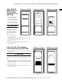
Einbau ZB-S 26, 18, 18C6, 10C6 in
elektrischen Betriebsraum EBR-S-2050
1. Anlage aufstellen und mit der Rückwand des Raumes
verschrauben.
ACHTUNG
Um Schrauben in das Brandschutzmaterial einschrauben
zu können, müssen die Löcher hierfür vorgebohrt werden.
Bohrlochtiefe: max. 25 mm, Schraubenlänge: max. 25
mm.
2. Technische Belüftung montieren (siehe Montage- und
Bedienungsanleitung ELEKTRISCHER BETRIEBSRAUM
PRIORACK-Elt EBR)
3. Das Dachblech der ZB-S demontieren. Kabel-
abfangsystem montieren (siehe Zeichnung).
4. Leitungen einführen.
5. Anlage gemäß CEAG Anleitung ZB-S anschließen und
in Betrieb nehmen.
ZB-S 26 und ZB-S 18 in
EBR-S-2050
ZB-S 18C6 und ZB-S 10C6 in
EBR-S-2050
D

5
Maximale Anzahl von Kabelschotts
Einbauanleitung Zentralbatterie-System ZB-S in elektrische Betriebsräume Typ EBR-S 40071860238 (A) August 2014 www.ceag.de
Tabelle 1: Technische Daten
Typ ZB-S/26 ZB-S/18 ZB-S/LAD Batterieschrank ZB-S/10C ZB-C/26C6 ZB-S/18C6 ZB-S/10C6 ZB-S/18C3 ZB-S/10C3 ZB-S/2C3 CG 200 CG 100
Elektrischer Betriebsraum inklusive Kabel-
und Lüftungsschott. Montiert ab Werk
EBR-S-2050-M EBR-S-2050-M EBR-S-2050-M EBR-S-2050-M EBR-S-2050-M
Projektspezifische Planung mit Aufmaß vor Ort notwendig.
EBR-S-2050-M EBR-S-2050-M EBR-S-1800-M EBR-S-1800-M EBR-S-1800-M EBR-S-1800-M EBR-S-1800-M
CEAG Sachnummer 40036071113 40036071113 40036071113 40036071113 40036071113 40036071113 40036071113 40036071111 40036071111 40036071111 40036071111 40036071111
Elektrischer Betriebsraum inklusive Kabel-
und Lüftungsschott. Selbstmontage
EBR-S-2050 EBR-S-2050 EBR-S-2050 EBR-S-2050 EBR-S-2050 EBR-S-2050 EBR-S-2050 EBR-S-1800 EBR-S-1800 EBR-S-1800 EBR-S-1800 EBR-S-1800
CEAG Sachnummer 40036071112 40036071112 40036071112 40036071112 40036071112 40036071112 40036071112 40036071110 40036071110 40036071110 40036071110 40036071110
Einbau der Anlage in montierten Raum
nachträglich möglich
nein nein nein nein nein nein nein ja ja ja ja ja
Max. Luft-Volumenstrom [m³/h]
gem. EN50272-2 für Starkladung*
3,86 2,32 3,86 3,86 1,01 1,01 0,60 0,51 0,22
Max. Wärmeverlustleistung [W]* 800 700 600 13 300 400 350 250 200 150 200 80
Anzahl Kabelschott KRS 125 für 26 Leitungen
3 x 2,5 mm² oder 10 Leitungen a 3 x 25/16 mm²
4 4 4 4 4 4 4 2 2 2 2 2
Max Anzahl Leitungen 2,5 mm² 78 78 8 - 78 78 78 26 26 26 26 26
Max Anzahl Leitungen 25 mm² 10 10 10 2 10 10 10 10 10 10 10 10
Abmessungen [HxBxT; mm] 2417x1144x736 2417x1144x736 2417x1144x736 2417x1144x736 2417x1144x736 2417x1144x736 2417x1144x736 2262x894x586 2262x894x586 2262x894x586 2262x894x586 2262x894x586
Gewicht (ca.) Raum/Anlage [kg] 692/180 692/170 692/170 692/170** 692/155 692/205 692/200 459/120 459/115 459/50 459/110 459/35
Zubehör
Maximale Anzahl von zusätzlichen Kabelschotts
KRS 125. Pro Kabelschott max. 26 Leitungen
3 x 2,5 mm² oder 10 Leitungen a 3 x 25/16 mm²
(siehe Abb. Seite 5)
6 6 6 6 6
6 6 4 4 4 4 4
Sockel mit Sockelblende 1060 mm breit EBR-S-2050-SO EBR-S-2050-SO EBR-S-2050-SO EBR-S-2050-SO EBR-S-2050-SO EBR-S-2050-SO EBR-S-2050-SO - - - - -
CEAG Sachnummer 40036071115 40036071115 40036071115 40036071115 40036071115 40036071115 40036071115 - - - - -
Sockel mit Sockelblende 810 mm breit - - - - - - - EBR-S-1800-SO EBR-S-1800-SO EBR-S-1800-SO EBR-S-1800-SO EBR-S-1800-SO
CEAG Sachnummer - - - - - - - 40036071114 40036071114 40036071114 40036071114 40036071114
Abfangschiene Leitungseinführung inkl.
Befestigungsmaterial
40071361160 40071361160 40071361160 - 40071361160 40071361161 40071361161 - - - - -
Montagesockel für Wandschränke - - - - - - - - - 40071360410 - 40071360410
Türanschlag links Keine Mehrkosten, jedoch Lieferzeit 6 Wochen. Keine Mehrkosten, jedoch Lieferzeit 6 Wochen.
* Eine Be- und Entlüftung für die Batterieladung und die Wärmeverluste ist vorzusehen. ** Ohne Batterien
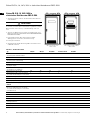
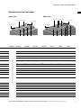
Maximale Anzahl von Kabelschotts
Kabeleinfühtung Ø 125
Zuluft DN 100
Abluft DN 100
Zusätzlichen Kabelschotts Ø 125 (optional)
EBR-S 1800 EBR-S 2050
Kabeleinfühtung Ø 125
Zuluft DN 100
Abluft DN 100
Zusätzlichen Kabelschotts Ø 125 (optional)
D

6
Montage Abfangschiene Leitungseinführung ZB-S mit 600 mm Schranktiefe
Einbauanleitung Zentralbatterie-System ZB-S in elektrische Betriebsräume Typ EBR-S 40071860238 (A) August 2014 www.ceag.de
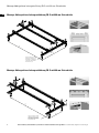
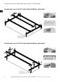
760
535
70,8
Zur Befestigung am Schrank
unbedingt zusätzlich die zur
Befestigung des Dachbleches
verwendeten Zahnscheiben
mitverwenden. (x4)
752
250
70,8
Zur Befestigung am Schrank
unbedingt zusätzlich die zur
Befestigung des Dachbleches
verwendeten Zahnscheiben
mitverwenden. (x4)
Montage Abfangschiene Leitungseinführung ZB-S mit 600 mm Schranktiefe
Montage Abfangschiene Leitungseinführung ZB-S mit 400 mm Schranktiefe
D

7
Installation of ZB-S 2C3, CG100, CG 102 and CG 104 in the EBR-S-1800 electrical service room
Manual: ZB-S central battery system in electrical service rooms EBR-S 40071860238 (A) August 2014 www.ceag.de
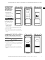
Installation of ZB-S
2C3, CG100, CG 102
and CG 104 in the
EBR-S-1800 electri-
cal service room
1. Screw-fasten the
base for ELT rooms
40071360410 to the rear
wall of the room.
2. Align the system and
screw-fasten to the rear
wall of the room.
CAUTION
Holes must be pre-drilled
for fastening screws into
the fire protection material.
Drill hole depth: max. 25
mm, screw length: max.
25 mm.
3. Set up the technical
ventilation (see the
installation and ope-
rating instructions
ELECTRICAL SERVICE ROOM PRIORACK-Elt EBR)
4. Feed in the cables.
5. Connect the system in accordance with the CEAG
ZB-S instructions and carry out commissioning of the
system.
Installation of ZB-S 18C3, 10C3 and CG200 in
the EBR-S-1800 electrical service room
1. Align the system and screw-fasten to the rear wall of
the room.
CAUTION
Holes must be pre-drilled for fastening screws into the
fire protection material. Drill hole depth: max. 25 mm,
screw length: max. 25 mm.
2. Set up the technical ventilation (see the installation and
operating instructions ELECTRICAL SERVICE ROOM
PRIORACK-Elt EBR)
3. Feed in the cables.
4. Connect the system in accordance with the CEAG
ZB-S instructions and carry out commissioning of the
system.
ZB-S 2C3 in EBR-S-1800 CG100 in EBR-S-1800 CG102, 104 in EBR-S-1800
ZB-S 18C3 and ZB-S 10C3 in
EBR-S-1800
CG200 in EBR-S-1800
GB

8
Installation of ZB-S 26, 18, 18C6, 10C6 in the EBR-S-2050 electrical service room
Manual: ZB-S central battery system in electrical service rooms EBR-S 40071860238 (A) August 2014 www.ceag.de
Tabelle 2: Technical data
Type ZB-S/26 ZB-S/18 ZB-S/LAD Battery cabinet ZB-S/10C ZB-C/26C6 ZB-S/18C6 ZB-S/10C6 ZB-S/18C3 ZB-S/10C3 ZB-S/2C3 CG 200 CG 100
Electrical service room including cable barrier
and ventilation barrier. Mounted ex works
EBR-S-2050-M EBR-S-2050-M EBR-S-2050-M EBR-S-2050-M EBR-S-2050-M
Project-specific planning on-site is necessary with oversize.
EBR-S-2050-M EBR-S-2050-M EBR-S-1800-M EBR-S-1800-M EBR-S-1800-M EBR-S-1800-M EBR-S-1800-M
CEAG part number 40036071113 40036071113 40036071113 40036071113 40036071113 40036071113 40036071113 40036071111 40036071111 40036071111 40036071111 40036071111
Electrical service room including cable barrier
and ventilation barrier. Self-assembly
EBR-S-2050 EBR-S-2050 EBR-S-2050 EBR-S-2050 EBR-S-2050 EBR-S-2050 EBR-S-2050 EBR-S-1800 EBR-S-1800 EBR-S-1800 EBR-S-1800 EBR-S-1800
CEAG part number 40036071112 40036071112 40036071112 40036071112 40036071112 40036071112 40036071112 40036071110 40036071110 40036071110 40036071110 40036071110
Installation of the system in an assembled
room is possible at a later date
no no no no no no no yes yes yes yes yes
Max. airflow [m³/h] acc to. EN50272-2
for boost charge*
3.86 2.32 3.86 3.86 1.01 1.01 0.60 0.51 0.22
Max. heat loss rate [W]* 800 700 600 13 300 400 350 250 200 150 200 80
No. of KRS 125 cable sealings for 26 cables
3 x 2.5 mm² or 10 cables at 3 x 25/16 mm²
4 4 4 4 4 4 4 2 2 2 2 2
Max. no. of 2.5 mm² cables 78 78 8 - 78 78 78 26 26 26 26 26
Max. no. of 25 mm² cables 10 10 10 2 10 10 10 10 10 10 10 10
Dimensions [HxWxD; mm] 2417x1144x736 2417x1144x736 2417x1144x736 2417x1144x736 2417x1144x736 2417x1144x736 2417x1144x736 2262x894x586 2262x894x586 2262x894x586 2262x894x586 2262x894x586
Weight (approx.) room/system [kg] 692/180 692/170 692/170 692/170** 692/155 692/205 692/200 459/120 459/115 459/50 459/110 459/35
Accessories
Maximum number of supplementary KRS 125
cable sealings. Max. 26 cables per cable sealing
3 x 2.5 mm² or 10 cables at 3 x 25/16 mm²
(see figure on page 5)
6 6 6 6 6
6 6 4 4 4 4 4
Plinth with plinth panel, width 1060 mm EBR-S-2050-SO EBR-S-2050-SO EBR-S-2050-SO EBR-S-2050-SO EBR-S-2050-SO EBR-S-2050-SO EBR-S-2050-SO - - - - -
CEAG part number 40036071115 40036071115 40036071115 40036071115 40036071115 40036071115 40036071115 - - - - -
Plinth with plinth panel, width 810 mm - - - - - - - EBR-S-1800-SO EBR-S-1800-SO EBR-S-1800-SO EBR-S-1800-SO EBR-S-1800-SO
CEAG part number - - - - - - - 40036071114 40036071114 40036071114 40036071114 40036071114
Stop rail, cable infeed incl. fixing material 40071361160 40071361160 40071361160 - 40071361160 40071361161 40071361161 - - - - -
Mounting plinth for wall cabinets - - - - - - - - - 40071360410 - 40071360410
Door stop, left No additional costs but 6 weeks of delivery time. No additional costs but 6 weeks of delivery time.
* Ventilation for the battery charge and heat dissipation must be provided. ** Without batteries
Installation of ZB-S 26, 18, 18C6, 10C6 in the
EBR-S-2050 electrical service room
1. Align the system and screw-fasten to the rear wall of
the room.
CAUTION
Holes must be pre-drilled for fastening screws into the
fire protection material. Drill hole depth: max. 25 mm,
screw length: max. 25 mm.
2. Set up the technical ventilation (see the installation and
operating instructions ELECTRICAL SERVICE ROOM
PRIORACK-Elt EBR)
3. Disassemble the roof plate of the ZB-S. Mount the
cable interception system (see the drawing).
4. Feed in the cables.
5. Connect the system in accordance with the CEAG
ZB-S instructions and carry out commissioning of the
system.
ZB-S 26 and ZB-S 18 in
EBR-S-2050
ZB-S 18C6 and ZB-S 10C6 in
EBR-S-2050
GB

9
Maximum number of cable sealings
Manual: ZB-S central battery system in electrical service rooms EBR-S 40071860238 (A) August 2014 www.ceag.de
Tabelle 2: Technical data
Type ZB-S/26 ZB-S/18 ZB-S/LAD Battery cabinet ZB-S/10C ZB-C/26C6 ZB-S/18C6 ZB-S/10C6 ZB-S/18C3 ZB-S/10C3 ZB-S/2C3 CG 200 CG 100
Electrical service room including cable barrier
and ventilation barrier. Mounted ex works
EBR-S-2050-M EBR-S-2050-M EBR-S-2050-M EBR-S-2050-M EBR-S-2050-M
Project-specific planning on-site is necessary with oversize.
EBR-S-2050-M EBR-S-2050-M EBR-S-1800-M EBR-S-1800-M EBR-S-1800-M EBR-S-1800-M EBR-S-1800-M
CEAG part number 40036071113 40036071113 40036071113 40036071113 40036071113 40036071113 40036071113 40036071111 40036071111 40036071111 40036071111 40036071111
Electrical service room including cable barrier
and ventilation barrier. Self-assembly
EBR-S-2050 EBR-S-2050 EBR-S-2050 EBR-S-2050 EBR-S-2050 EBR-S-2050 EBR-S-2050 EBR-S-1800 EBR-S-1800 EBR-S-1800 EBR-S-1800 EBR-S-1800
CEAG part number 40036071112 40036071112 40036071112 40036071112 40036071112 40036071112 40036071112 40036071110 40036071110 40036071110 40036071110 40036071110
Installation of the system in an assembled
room is possible at a later date
no no no no no no no yes yes yes yes yes
Max. airflow [m³/h] acc to. EN50272-2
for boost charge*
3.86 2.32 3.86 3.86 1.01 1.01 0.60 0.51 0.22
Max. heat loss rate [W]* 800 700 600 13 300 400 350 250 200 150 200 80
No. of KRS 125 cable sealings for 26 cables
3 x 2.5 mm² or 10 cables at 3 x 25/16 mm²
4 4 4 4 4 4 4 2 2 2 2 2
Max. no. of 2.5 mm² cables 78 78 8 - 78 78 78 26 26 26 26 26
Max. no. of 25 mm² cables 10 10 10 2 10 10 10 10 10 10 10 10
Dimensions [HxWxD; mm] 2417x1144x736 2417x1144x736 2417x1144x736 2417x1144x736 2417x1144x736 2417x1144x736 2417x1144x736 2262x894x586 2262x894x586 2262x894x586 2262x894x586 2262x894x586
Weight (approx.) room/system [kg] 692/180 692/170 692/170 692/170** 692/155 692/205 692/200 459/120 459/115 459/50 459/110 459/35
Accessories
Maximum number of supplementary KRS 125
cable sealings. Max. 26 cables per cable sealing
3 x 2.5 mm² or 10 cables at 3 x 25/16 mm²
(see figure on page 5)
6 6 6 6 6
6 6 4 4 4 4 4
Plinth with plinth panel, width 1060 mm EBR-S-2050-SO EBR-S-2050-SO EBR-S-2050-SO EBR-S-2050-SO EBR-S-2050-SO EBR-S-2050-SO EBR-S-2050-SO - - - - -
CEAG part number 40036071115 40036071115 40036071115 40036071115 40036071115 40036071115 40036071115 - - - - -
Plinth with plinth panel, width 810 mm - - - - - - - EBR-S-1800-SO EBR-S-1800-SO EBR-S-1800-SO EBR-S-1800-SO EBR-S-1800-SO
CEAG part number - - - - - - - 40036071114 40036071114 40036071114 40036071114 40036071114
Stop rail, cable infeed incl. fixing material 40071361160 40071361160 40071361160 - 40071361160 40071361161 40071361161 - - - - -
Mounting plinth for wall cabinets - - - - - - - - - 40071360410 - 40071360410
Door stop, left No additional costs but 6 weeks of delivery time. No additional costs but 6 weeks of delivery time.
* Ventilation for the battery charge and heat dissipation must be provided. ** Without batteries
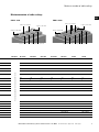
Maximum number of cable sealings
Cable infeed Ø 125
Supply air DN 100
Waste air DN 100
Supplementary cable sealing Ø 125 (optional)
EBR-S 1800 EBR-S 2050
Cable infeed Ø 125
Supply air DN 100
Waste air DN 100
Supplementary cable sealing Ø 125 (optional)
GB

10
Assembling the stop rail for ZB-S cable infeed with 600 mm cabinet depth
Manual: ZB-S central battery system in electrical service rooms EBR-S 40071860238 (A) August 2014 www.ceag.de
760
535
70.8
When mounting to the
cabinet, ensure you also use
the serrated washers used
for fixing the roof plate. (x4)
752
250
70.8
When mounting to the
cabinet, ensure you also use
the serrated washers used
for fixing the roof plate. (x4)
Assembling the stop rail for ZB-S cable infeed with 600 mm cabinet depth
Assembling the stop rail for ZB-S cable infeed with 400 mm cabinet depth
GB

11
Manual: ZB-S central battery system in electrical service rooms EBR-S 40071860238 (A) August 2014 www.ceag.de
GB

Eaton ist ein eingetragenes
Warenzeichen.
Alle anderen Warenzeichen sind
Eigentum Ihrer jeweiligen Inhaber.
Eaton is a registered trademark.
All other trademarks are property
of their respective owners.
Eatons Ziel ist es, zuverlässige, effiziente und sichere Strom-
versorgung dann zu bieten, wenn sie am meisten benötigt
wird. Die Experten von Eaton verfügen über ein umfassendes
Fachwissen im Bereich Energiemanagement in verschiedens-
ten Branchen und sorgen so für kundenspezifische, integrier-
te Lösungen, um anspruchsvollste Anforderungen der Kunden
zu erfüllen.
Wir sind darauf fokussiert, stets die richtige Lösung für jede
Anwendung zu finden. Dabei erwarten Entscheidungsträger
mehr als lediglich innovative Produkte. Unternehmen wenden
sich an Eaton, weil individuelle Unterstützung und der Erfolg
unserer Kunden stets an erster Stelle stehen. Für mehr Infor-
mationen besuchen Sie www.eaton.eu.
Ihre Ansprechpartner finden Sie unter www.ceag.de.
Eaton Industries Manufacturing GmbH
Electrical Sector EMEA
Route de la Longeraie 7
1110 Morges, Switzerland
Eaton.eu
CEAG Notlichtsysteme GmbH
Senator-Schwartz-Ring 26
59494 Soest, Germany
Tel.: +49 (0) 2921 69-870
Fax: +49 (0) 2921 69-617
E-Mail: [email protected]
Web: www.ceag.de
© 2014 Eaton
Alle Rechte vorbehalten
Printed in Germany
Bestell-Nr. 40071860238 (A)
August 2014
Eaton is dedicated to ensuring that reliable, efficient and safe
power is available when it’s needed most. With unparalleled
knowledge of electrical power management across industries,
experts at Eaton deliver customized, integrated solutions to
solve our customers’ most critical challenges.
Our focus is on delivering the right solution for the application.
But, decision makers demand more than just innovative pro-
ducts. They turn to Eaton for an unwavering commitment to
personal support that makes customer success a top priority.
For more information, visit www.eaton.com/electrical.
To find your contact person, visit www.ceag.de.
-
 1
1
-
 2
2
-
 3
3
-
 4
4
-
 5
5
-
 6
6
-
 7
7
-
 8
8
-
 9
9
-
 10
10
-
 11
11
-
 12
12


Eaton ZB-S Series Installation Instructions Manual
- Typ
- Installation Instructions Manual
Verwandte Artikel
Andere Dokumente
-
 SH Engines EBR-5000 SL Benutzerhandbuch
-
Sharp EBR47ST Bedienungsanleitung
-
Boston Acoustics E60 Bedienungsanleitung
-
Carson RP-100 Benutzerhandbuch
-
Cooltek 100800410 Datenblatt
-
-
-
Siemens VSQ8M1/03 Benutzerhandbuch
-
Pioneer HDJ-X5 Silver Benutzerhandbuch
