Sound Performance Lab Channel One Mk3 Bedienungsanleitung
- Kategorie
- Audio-Equalizer
- Typ
- Bedienungsanleitung

More information: spl.audio
Manual
Channel One Mk3
Channel Strip
DISCRETE PREAMPLIFIER DE-ESSER
Channel One
VU VU
+12
0
+6
OUT
IN
GR
T
U
B
E
S
A
T
U
R
A
T
I
O
N
O
F
F
%
G
A
I
N
dB | Mic
VA B PAD
A
T
T
A
C
K
dB dB
C
O
M
P
R
E
S
S
I
O
N
-
.
-
.
-
-
-
-
-
-
-
-
S
R
E
D
U
C
T
I
O
N
dB
COMPRESSOR EQUALIZER & AIR BAND
TRANSIENT
DESIGNER
ON
EQ PRE TDDE-ESS OVL
TUBE POST
MUTE
ON ON
S
U
S
T
A
I
N
dB
-
-
-
-
-
-
-
-
-
-
M
A
K
E
-
U
P
G
A
I
N
dB
.
–
+
dB
-
-
-
.
-
-
.
.
.
-
-
-
.
-
-
.
.
.
–
+
dB
M
H
F
Hz
k
k
k
k
k
k
k
k
k
O
U
T
P
U
T
dB
-
-
-
-
-
.
A
I
R
dB
-
-
-
-
-
I
N
S
T
R
U
M
E
N
T
Mk
L
M
F
Hz
INPUT
Mic A
Line/Inst
Mic B
LOW HIGH
-
.
-
-
-
-
-
-
-
-
-
Model
2130
Ø
EN
DE

Channel One Mk3 – Manual
2
Getting started
Read the safety instructions starting on page 14.
Make sure that the mains voltage of the Channel One Mk3 corresponds to the voltage
of your region and that the fuse has the correct value for the selected voltage
(see specications on page 12).
The power switch on the back of the Channel One Mk3 must be in the o position.
(O = O / On = I).
Connect the supplied power cord to the power connector of the Channel One Mk3 and to a
power outlet.
If the supplied power cord does not match your mains socket outlet, please contact your dealer.
The devices that are to be connected to the Channel One Mk3 must be be switched o.
Connect your devices with appropriate audio cables (XLR) to the inputs and outputs of the
Channel One Mk 3.
Audio cables not included in the scope of delivery.
Power on
Switch on the power switch on the rear panel of the Channel One Mk3 (On = I).
The PWR LED and all activated switches light up.
Activating phantom power
Please always follow these instructions to active and deactivate phantom power – also
when changing microphones. The input stage of the Channel One Mk3 can be damaged if
you ignore these procedures.
1. Connect the microphone to the Channel One Mk 3.
2. Now activate phantom power to use the microphone.
3. When recording is completed, rst thing is to deactivate the phantom power.
4. Wait at least one minute aer deactivation of phantom power before disconnecting the
microphone! This ensures residual current will be discharged.
Power o
Switch o the power switch on the rear panel of the Channel One Mk 3 (O = O).
The PWR LED and all activated switches no longer light up.

Channel One Mk3 – Manual
3
Mic A – Input, XLR
Out 2 – Output, XLR Out 1 – Output, XLR
Line In – Input, XLR
Mic B – Input, XLRPreamp Out – Output, XLR
Power switch
Mains input
Voltage selector
Ground li switch
EN
DE

Channel One Mk3 – Manual
4
Discrete Preamplier
Channel One Mk3 is equipped with one discrete preamplier.
DISCRETE PREAMPLIFIER DE-ESSER
Channel One
VU VU
+12
0
+6
OUT
IN
GR
T
U
B
E
S
A
T
U
R
A
T
I
O
N
O
F
F
%
G
A
I
N
dB | Mic
VA B PAD
A
T
T
A
C
K
dB dB
C
O
M
P
R
E
S
S
I
O
N
-
.
-
.
-
-
-
-
-
-
-
-
S
R
E
D
U
C
T
I
O
N
dB
COMPRESSOR EQUALIZER & AIR BAND
TRANSIENT
DESIGNER
ON
EQ PRE TDDE-ESS OVL
TUBE POST
MUTE
ON ON
S
U
S
T
A
I
N
dB
-
-
-
-
-
-
-
-
-
-
M
A
K
E
-
U
P
G
A
I
N
dB
.
–
+
dB
-
-
-
.
-
-
.
.
.
-
-
-
.
-
-
.
.
.
–
+
dB
M
H
F
Hz
k
k
k
k
k
k
k
k
k
O
U
T
P
U
T
dB
-
-
-
-
-
.
A
I
R
dB
-
-
-
-
-
I
N
S
T
R
U
M
E
N
T
Mk
L
M
F
Hz
INPUT
Mic A
Line/Inst
Mic B
LOW HIGH
-
.
-
-
-
-
-
-
-
-
-
Model
2130
Ø
Line In
Low impedance line signals (less than 1 kΩ) should be
connected to the rear panel Line In input.
Mic A, Mic B, Line/Inst
This switch is used to select the input source.
Mic In A & Mic In B
Microphones of all types can be connected to the Mic input
(dynamic, condenser, tube and ribbon). Channel One Mk3
oers two microphone inputs on the rear – for Mic A and
Mic B. Two microphones can be connected here.
Instrument
The instrument input is the only input on the front panel for
easy access at any time. It is designed for the connection of
high-impedance (higher than 1 kΩ) instruments.
IMPORTANT: As long as the instrument input is in use, the line input on the rear panel is
deactivated.
DISCRETE PREAMPLIFIER DE-ESSER
Channel One
VU VU
+12
0
+6
OUT
IN
GR
T
U
B
E
S
A
T
U
R
A
T
I
O
N
O
F
F
%
G
A
I
N
dB | Mic
VA B PAD
A
T
T
A
C
K
dB dB
C
O
M
P
R
E
S
S
I
O
N
-
.
-
.
-
-
-
-
-
-
-
-
S
R
E
D
U
C
T
I
O
N
dB
COMPRESSOR EQUALIZER & AIR BAND
TRANSIENT
DESIGNER
ON
EQ PRE TDDE-ESS OVL
TUBE POST
MUTE
ON ON
S
U
S
T
A
I
N
dB
-
-
-
-
-
-
-
-
-
-
M
A
K
E
-
U
P
G
A
I
N
dB
.
–
+
dB
-
-
-
.
-
-
.
.
.
-
-
-
.
-
-
.
.
.
–
+
dB
M
H
F
Hz
k
k
k
k
k
k
k
k
k
O
U
T
P
U
T
dB
-
-
-
-
-
.
A
I
R
dB
-
-
-
-
-
I
N
S
T
R
U
M
E
N
T
Mk
L
M
F
Hz
INPUT
Mic A
Line/Inst
Mic B
LOW HIGH
-
.
-
-
-
-
-
-
-
-
-
Model
2130
Ø
RISK OF ELECTRIC SHOCK
DO NOT OPEN
CAUTION
RISQUE DE CHOC ÉLECTRIQUE
NE PAS OUVRIR
ATTENTION
Serial
Number
Made in Germanyspl.audio
MIC IN AMIC IN BLINE INPREAMP OUT
TO REDUCE RISK OF FIRE OR ELECTRIC SHOCK
DO NOT EXPOSE THIS UNIT
TO RAIN OR MOISTURE.
THIS EQUIPMENT MUST BE EARTHED.
WARNING
OUT 2
OUT 1
OUT 1
230 V: Fuse T 315 mA L 250V
115 V: Fuse T 630 mA L 250V
~115 V AC/~230 V AC,
50 Hz/60 Hz, P max. 30 W
AC MAINS
GND LIFT
GND LIFT
GND LIFT
GND
POWER
POWER
VOLTAGE
VOLTAGE
AC MAINS
OUT 2PREAMP OUTMIC IN A MIC IN B LINE IN
Mk
Channel One
230V

Channel One Mk3 – Manual
5
DISCRETE PREAMPLIFIER DE-ESSER
Channel One
VU VU
+12
0
+6
OUT
IN
GR
T
U
B
E
S
A
T
U
R
A
T
I
O
N
O
F
F
%
G
A
I
N
dB | Mic
VA B PAD
A
T
T
A
C
K
dB dB
C
O
M
P
R
E
S
S
I
O
N
-
.
-
.
-
-
-
-
-
-
-
-
S
R
E
D
U
C
T
I
O
N
dB
COMPRESSOR EQUALIZER & AIR BAND
TRANSIENT
DESIGNER
ON
EQ PRE TDDE-ESS OVL
TUBE POST
MUTE
ON ON
S
U
S
T
A
I
N
dB
-
-
-
-
-
-
-
-
-
-
M
A
K
E
-
U
P
G
A
I
N
dB
.
–
+
dB
-
-
-
.
-
-
.
.
.
-
-
-
.
-
-
.
.
.
–
+
dB
M
H
F
Hz
k
k
k
k
k
k
k
k
k
O
U
T
P
U
T
dB
-
-
-
-
-
.
A
I
R
dB
-
-
-
-
-
I
N
S
T
R
U
M
E
N
T
Mk
L
M
F
Hz
INPUT
Mic A
Line/Inst
Mic B
LOW HIGH
-
.
-
-
-
-
-
-
-
-
-
Model
2130
Ø
RISK OF ELECTRIC SHOCK
DO NOT OPEN
CAUTION
RISQUE DE CHOC ÉLECTRIQUE
NE PAS OUVRIR
ATTENTION
Serial
Number
Made in Germanyspl.audio
MIC IN AMIC IN BLINE INPREAMP OUT
TO REDUCE RISK OF FIRE OR ELECTRIC SHOCK
DO NOT EXPOSE THIS UNIT
TO RAIN OR MOISTURE.
THIS EQUIPMENT MUST BE EARTHED.
WARNING
OUT 2
OUT 1
OUT 1
230 V: Fuse T 315 mA L 250V
115 V: Fuse T 630 mA L 250V
~115 V AC/~230 V AC,
50 Hz/60 Hz, P max. 30 W
AC MAINS
GND LIFT
GND LIFT
GND LIFT
GND
POWER
POWER
VOLTAGE
VOLTAGE
AC MAINS
OUT 2PREAMP OUTMIC IN A MIC IN B LINE IN
Mk
Channel One
230V
GND Li
The GND switch can be used to eliminate ground loops by
disconnecting the internal ground from the housing ground
when the switch is pressed.
Gain
The gain control can be used to adjust the preamplication.
For microphone signals, a preamplication of up to 68 dB
can be realized. When optionally equipped with an input
transformer, approximately +14 dB must be added to the
scaled values.
The control range for line signals ranges between -20 dB and +16 dB.
The control range for instrument signals ranges between -6 dB und +30 dB.
48V
The 48V switch activates the phantom power of 48 volts
required for the use of con- denser microphones.
Phantom power can be activated individually for both
microphone inputs!
PAD
The PAD switch attenuates the signal of the microphone
input by 20 dB, so that even very high levels can be
processed with the Channel One Mk3.
ø
The phase reverse function reverses the polarity of the signal.
Aer pressing the switch, the phase is reversed by 180°.
A highpass lter with 6 dB per octave reduces impact noise
below 80 Hz. This lter can be used for both preampliers.
EN
DE

Channel One Mk3 – Manual
6
DISCRETE PREAMPLIFIER DE-ESSER
Channel One
VU VU
+12
0
+6
OUT
IN
GR
T
U
B
E
S
A
T
U
R
A
T
I
O
N
O
F
F
%
G
A
I
N
dB | Mic
VA B PAD
A
T
T
A
C
K
dB dB
C
O
M
P
R
E
S
S
I
O
N
-
.
-
.
-
-
-
-
-
-
-
-
S
R
E
D
U
C
T
I
O
N
dB
COMPRESSOR EQUALIZER & AIR BAND
TRANSIENT
DESIGNER
ON
EQ PRE TDDE-ESS OVL
TUBE POST
MUTE
ON ON
S
U
S
T
A
I
N
dB
-
-
-
-
-
-
-
-
-
-
M
A
K
E
-
U
P
G
A
I
N
dB
.
–
+
dB
-
-
-
.
-
-
.
.
.
-
-
-
.
-
-
.
.
.
–
+
dB
M
H
F
Hz
k
k
k
k
k
k
k
k
k
O
U
T
P
U
T
dB
-
-
-
-
-
.
A
I
R
dB
-
-
-
-
-
I
N
S
T
R
U
M
E
N
T
Mk
L
M
F
Hz
INPUT
Mic A
Line/Inst
Mic B
LOW HIGH
-
.
-
-
-
-
-
-
-
-
-
Model
2130
Ø
The DE-ESS LED lights up as soon as an S-sound is detected.
It is only active when the de-esser is switched on, but it works
independently of the set reduction value. In other words, it
always indicates that the circuit is detecting sibilants – so your
attention is always drawn to any need for adjustment.
DISCRETE PREAMPLIFIER DE-ESSER
Channel One
VU VU
+12
0
+6
OUT
IN
GR
T
U
B
E
S
A
T
U
R
A
T
I
O
N
O
F
F
%
G
A
I
N
dB | Mic
VA B PAD
A
T
T
A
C
K
dB dB
C
O
M
P
R
E
S
S
I
O
N
-
.
-
.
-
-
-
-
-
-
-
-
S
R
E
D
U
C
T
I
O
N
dB
COMPRESSOR EQUALIZER & AIR BAND
TRANSIENT
DESIGNER
ON
EQ PRE TDDE-ESS OVL
TUBE POST
MUTE
ON ON
S
U
S
T
A
I
N
dB
-
-
-
-
-
-
-
-
-
-
M
A
K
E
-
U
P
G
A
I
N
dB
.
–
+
dB
-
-
-
.
-
-
.
.
.
-
-
-
.
-
-
.
.
.
–
+
dB
M
H
F
Hz
k
k
k
k
k
k
k
k
k
O
U
T
P
U
T
dB
-
-
-
-
-
.
A
I
R
dB
-
-
-
-
-
I
N
S
T
R
U
M
E
N
T
Mk
L
M
F
Hz
INPUT
Mic A
Line/Inst
Mic B
LOW HIGH
-
.
-
-
-
-
-
-
-
-
-
Model
2130
Ø
OVL-LED
The OVL LED lights up as soon as an overload is detected in
the device. The indicator picks up at all relevant points of the
signal flow: behind the preamp, behind the tube saturation
stage, behind the Transient Designer, behind the compressor,
behind the equalizer and behind the output control.
Tube Post
The Tube Post switch changes the order of the Tube Saturation
within the signal flow: When the switch is pressed, the
Tube Saturation stage comes aer the EQ stage and before
the output stage; when the switch is not pressed, the Tube
Saturation stage comes directly behind the preamp and
before the de-esser.
S-Reduction
The S-Reduction control adjusts the intensity of the S-sound
reduction. In practice, S-Reduction settings between -2 dB and
-8 dB achieve the best results for most applications.
Tube Saturation
With this control the amount of tube saturation can be deter-
mined. In extreme settings the level increases by only 6 dB.
Therefore decent to expressive harmonic distortions can be
easily dialed in.

Channel One Mk3 – Manual
7
DISCRETE PREAMPLIFIER DE-ESSER
Channel One
VU VU
+12
0
+6
OUT
IN
GR
T
U
B
E
S
A
T
U
R
A
T
I
O
N
O
F
F
%
G
A
I
N
dB | Mic
VA B PAD
A
T
T
A
C
K
dB dB
C
O
M
P
R
E
S
S
I
O
N
-
.
-
.
-
-
-
-
-
-
-
-
S
R
E
D
U
C
T
I
O
N
dB
COMPRESSOR EQUALIZER & AIR BAND
TRANSIENT
DESIGNER
ON
EQ PRE TDDE-ESS OVL
TUBE POST
MUTE
ON ON
S
U
S
T
A
I
N
dB
-
-
-
-
-
-
-
-
-
-
M
A
K
E
-
U
P
G
A
I
N
dB
.
–
+
dB
-
-
-
.
-
-
.
.
.
-
-
-
.
-
-
.
.
.
–
+
dB
M
H
F
Hz
k
k
k
k
k
k
k
k
k
O
U
T
P
U
T
dB
-
-
-
-
-
.
A
I
R
dB
-
-
-
-
-
I
N
S
T
R
U
M
E
N
T
Mk
L
M
F
Hz
INPUT
Mic A
Line/Inst
Mic B
LOW HIGH
-
.
-
-
-
-
-
-
-
-
-
Model
2130
Ø
Low & High
The Low and High switches can be used to activate or
deactivate the low or high band de-esser, meaning a dierent
center frequency for the de-esser. If no switch is pressed, the
de-esser is not active. If the Low switch is pressed, the low
de-esser band is activated with a center frequency of 6.4 kHz
and a bandwidth of 4.4 kHz. If the High switch is pressed, the
high de-essing band with a center frequency of 11.2 kHz and a
bandwidth of 5.5 kHz is activated. If both switches are pressed,
Low and High band de-esser are active.
Attack
Attack can be used to increase or attenuate the transient
phase of a signal by up to 15 dB. A positive attack value
increases the amplitude of the transient response. Negative
attack values lead to an attenuation.
Sustain
Sustain can be used to increase or attenuate the sustain phase
of a signal by up to 24 dB. Positive sustain values extend the
sustain. Negative Sustain values shorten the sustain.
The On switch activates the Transient Designer section,
consisting of the Attack control and the Sustain control.
EN
DE

Channel One Mk3 – Manual
8
DISCRETE PREAMPLIFIER DE-ESSER
Channel One
VU VU
+12
0
+6
OUT
IN
GR
T
U
B
E
S
A
T
U
R
A
T
I
O
N
O
F
F
%
G
A
I
N
dB | Mic
VA B PAD
A
T
T
A
C
K
dB dB
C
O
M
P
R
E
S
S
I
O
N
-
.
-
.
-
-
-
-
-
-
-
-
S
R
E
D
U
C
T
I
O
N
dB
COMPRESSOR EQUALIZER & AIR BAND
TRANSIENT
DESIGNER
ON
EQ PRE TDDE-ESS OVL
TUBE POST
MUTE
ON ON
S
U
S
T
A
I
N
dB
-
-
-
-
-
-
-
-
-
-
M
A
K
E
-
U
P
G
A
I
N
dB
.
–
+
dB
-
-
-
.
-
-
.
.
.
-
-
-
.
-
-
.
.
.
–
+
dB
M
H
F
Hz
k
k
k
k
k
k
k
k
k
O
U
T
P
U
T
dB
-
-
-
-
-
.
A
I
R
dB
-
-
-
-
-
I
N
S
T
R
U
M
E
N
T
Mk
L
M
F
Hz
INPUT
Mic A
Line/Inst
Mic B
LOW HIGH
-
.
-
-
-
-
-
-
-
-
-
Model
2130
Ø
LMF
The center frequency of the half-parametric low/mid frequency
lter is set with the LMF control (low/mid frequencies).
The adjustable frequency range is between 30 Hz and
700 Hz so that this lter covers a range of about 4.5 octaves,
allowing it to be used from the deepest bass to the lower mid
range. This together with the MHF lter ensures that the entire
frequency spectrum is covered.
The LMF lter operates to the proportional-Q-principle, in other words the bandwidth is
dependent on the selected boost or cut.
The -/+ control (right to the LMF control) determines the boost
or cut of the LMF lter.
The maximum values are at +/- 12 dB.
DISCRETE PREAMPLIFIER DE-ESSER
Channel One
VU VU
+12
0
+6
OUT
IN
GR
T
U
B
E
S
A
T
U
R
A
T
I
O
N
O
F
F
%
G
A
I
N
dB | Mic
VA B PAD
A
T
T
A
C
K
dB dB
C
O
M
P
R
E
S
S
I
O
N
-
.
-
.
-
-
-
-
-
-
-
-
S
R
E
D
U
C
T
I
O
N
dB
COMPRESSOR EQUALIZER & AIR BAND
TRANSIENT
DESIGNER
ON
EQ PRE TDDE-ESS OVL
TUBE POST
MUTE
ON ON
S
U
S
T
A
I
N
dB
-
-
-
-
-
-
-
-
-
-
M
A
K
E
-
U
P
G
A
I
N
dB
.
–
+
dB
-
-
-
.
-
-
.
.
.
-
-
-
.
-
-
.
.
.
–
+
dB
M
H
F
Hz
k
k
k
k
k
k
k
k
k
O
U
T
P
U
T
dB
-
-
-
-
-
.
A
I
R
dB
-
-
-
-
-
I
N
S
T
R
U
M
E
N
T
Mk
L
M
F
Hz
INPUT
Mic A
Line/Inst
Mic B
LOW HIGH
-
.
-
-
-
-
-
-
-
-
-
Model
2130
Ø
Make-Up Gain
The Make-Up Gain control can be used to make up for the
overall level reduction caused by compression.
A value between 0 dB and 20 dB can be set by which the level
is increased again aer compression.
With the help of the Gain Reduction shown on the VU meter,
the adjustment is very simple: if the maximum reduction value
caused by the loudest part is e.g. -9 dB, the Make-Up Gain
control should be set to values around +9 dB.
The On switch activates the compressor section, consisting of
the compression control and the Make-Up Gain.
Compression
The Compression control can be used to set a threshold
between 0 dB and -20 dB. The lower the threshold, the more
the compressor works.

Channel One Mk3 – Manual
9
DISCRETE PREAMPLIFIER DE-ESSER
Channel One
VU VU
+12
0
+6
OUT
IN
GR
T
U
B
E
S
A
T
U
R
A
T
I
O
N
O
F
F
%
G
A
I
N
dB | Mic
VA B PAD
A
T
T
A
C
K
dB dB
C
O
M
P
R
E
S
S
I
O
N
-
.
-
.
-
-
-
-
-
-
-
-
S
R
E
D
U
C
T
I
O
N
dB
COMPRESSOR EQUALIZER & AIR BAND
TRANSIENT
DESIGNER
ON
EQ PRE TDDE-ESS OVL
TUBE POST
MUTE
ON ON
S
U
S
T
A
I
N
dB
-
-
-
-
-
-
-
-
-
-
M
A
K
E
-
U
P
G
A
I
N
dB
.
–
+
dB
-
-
-
.
-
-
.
.
.
-
-
-
.
-
-
.
.
.
–
+
dB
M
H
F
Hz
k
k
k
k
k
k
k
k
k
O
U
T
P
U
T
dB
-
-
-
-
-
.
A
I
R
dB
-
-
-
-
-
I
N
S
T
R
U
M
E
N
T
Mk
L
M
F
Hz
INPUT
Mic A
Line/Inst
Mic B
LOW HIGH
-
.
-
-
-
-
-
-
-
-
-
Model
2130
Ø
MHF
The center frequency of the semi-parametric mid/high
frequency lter is set with the MHF control. (MHF: mid/high
frequencies). The frequency range can be set between 680 Hz
and 15 kHz so that this lter covers a range of 4.5 octaves and
can be equally be used in the lower mid as well as the high
frequency range.
The MHF lter operates to the proportional-Q-principle, in other words the bandwidth is
dependent on the selected boost or cut.
AIR
The high frequency lter in the equalizer module is labeled as
AIR. A coil-capacitor lter with so called bell characteristics and
a center frequency of 19 kHz comes into operation here.
At this frequency the maximum possible accentuation is
+10 dB, the maximum possible damping is -10 dB.
EQ pre TD
The EQ pre TD switch swaps the order of the Equalizer and
Transient Designer: if the switch is pressed, the Equalizer is
placed in front of the Transient Designer; if the switch is not
pressed, the order remains unchanged.
The equalizer section is activated via the On switch.
The -/+ control (right to the MHF control) determines the cut of
the MHF lter.
The maximum values are at +/- 12 dB.
DISCRETE PREAMPLIFIER DE-ESSER
Channel One
VU VU
+12
0
+6
OUT
IN
GR
T
U
B
E
S
A
T
U
R
A
T
I
O
N
O
F
F
%
G
A
I
N
dB | Mic
VA B PAD
A
T
T
A
C
K
dB dB
C
O
M
P
R
E
S
S
I
O
N
-
.
-
.
-
-
-
-
-
-
-
-
S
R
E
D
U
C
T
I
O
N
dB
COMPRESSOR EQUALIZER & AIR BAND
TRANSIENT
DESIGNER
ON
EQ PRE TDDE-ESS OVL
TUBE POST
MUTE
ON ON
S
U
S
T
A
I
N
dB
-
-
-
-
-
-
-
-
-
-
M
A
K
E
-
U
P
G
A
I
N
dB
.
–
+
dB
-
-
-
.
-
-
.
.
.
-
-
-
.
-
-
.
.
.
–
+
dB
M
H
F
Hz
k
k
k
k
k
k
k
k
k
O
U
T
P
U
T
dB
-
-
-
-
-
.
A
I
R
dB
-
-
-
-
-
I
N
S
T
R
U
M
E
N
T
Mk
L
M
F
Hz
INPUT
Mic A
Line/Inst
Mic B
LOW HIGH
-
.
-
-
-
-
-
-
-
-
-
Model
2130
Ø
EN
DE

Channel One Mk3 – Manual
10
DISCRETE PREAMPLIFIER DE-ESSER
Channel One
VU VU
+12
0
+6
OUT
IN
GR
T
U
B
E
S
A
T
U
R
A
T
I
O
N
O
F
F
%
G
A
I
N
dB | Mic
VA B PAD
A
T
T
A
C
K
dB dB
C
O
M
P
R
E
S
S
I
O
N
-
.
-
.
-
-
-
-
-
-
-
-
S
R
E
D
U
C
T
I
O
N
dB
COMPRESSOR EQUALIZER & AIR BAND
TRANSIENT
DESIGNER
ON
EQ PRE TDDE-ESS OVL
TUBE POST
MUTE
ON ON
S
U
S
T
A
I
N
dB
-
-
-
-
-
-
-
-
-
-
M
A
K
E
-
U
P
G
A
I
N
dB
.
–
+
dB
-
-
-
.
-
-
.
.
.
-
-
-
.
-
-
.
.
.
–
+
dB
M
H
F
Hz
k
k
k
k
k
k
k
k
k
O
U
T
P
U
T
dB
-
-
-
-
-
.
A
I
R
dB
-
-
-
-
-
I
N
S
T
R
U
M
E
N
T
Mk
L
M
F
Hz
INPUT
Mic A
Line/Inst
Mic B
LOW HIGH
-
.
-
-
-
-
-
-
-
-
-
Model
2130
Ø
Output
With the output control, the output level can be attenuated by
up to -20 dB or amplied by a maximum of +6 dB. This ensures
that following devices or AD converters can receive an optimal
output level.
The respective set output level is displayed on the big
VU meter when the VU switch is in the Out position.
Out 1 & Out 2
These balanced output connectors provide the output signal.
The Channel One Mk3 provides two parallel outputs each.
Preamp Out
This balanced preamp-out is not to be underestimated.
This output is the pure pre-amplied microphone signal -
without any processing of the Channel One Mk3‘s
processing tools.
Mute
The Mute switch mutes all output signals; when activated the
VU meter displays no output level (VU meter switch in
Out position).

Channel One Mk3 – Manual
11
DISCRETE PREAMPLIFIER DE-ESSER
Channel One
VU VU
+12
0
+6
OUT
IN
GR
T
U
B
E
S
A
T
U
R
A
T
I
O
N
O
F
F
%
G
A
I
N
dB | Mic
VA B PAD
A
T
T
A
C
K
dB dB
C
O
M
P
R
E
S
S
I
O
N
-
.
-
.
-
-
-
-
-
-
-
-
S
R
E
D
U
C
T
I
O
N
dB
COMPRESSOR EQUALIZER & AIR BAND
TRANSIENT
DESIGNER
ON
EQ PRE TDDE-ESS OVL
TUBE POST
MUTE
ON ON
S
U
S
T
A
I
N
dB
-
-
-
-
-
-
-
-
-
-
M
A
K
E
-
U
P
G
A
I
N
dB
.
–
+
dB
-
-
-
.
-
-
.
.
.
-
-
-
.
-
-
.
.
.
–
+
dB
M
H
F
Hz
k
k
k
k
k
k
k
k
k
O
U
T
P
U
T
dB
-
-
-
-
-
.
A
I
R
dB
-
-
-
-
-
I
N
S
T
R
U
M
E
N
T
Mk
L
M
F
Hz
INPUT
Mic A
Line/Inst
Mic B
LOW HIGH
-
.
-
-
-
-
-
-
-
-
-
Model
2130
Ø
The VU-Meter
The illuminated VU meter displays the input level, output level
and gain reduction.
VU
The VU switch on the right below the VU meter can be used to
select which level is displayed in the VU meter.
GR: Gain Reduction
In: Input Level
Out: Output Level
VU
For a better and more intuitive display of the signal levels the
VU switch on the le side below the VU meter can be adjusted
to the display range of the VU meter to dierent signal levels.
In switch position 0, 0 dB on the VU meter corresponds to an
output level of + 6 dBu.
In the +6 switch position, 0 dB on the VU meter corresponds to
an output level of +12 dBu.
In the +12 switch position, 0 dB on the VU meter corresponds
to an output level of +18 dBu.
EN
DE

Channel One Mk3 – Manual
12
Internal Linear Power Supply with Shielded Toroidal Transformer
Operating voltage for analog audio +/- 18 V
Operating voltage for relays and LEDs +12 V
Tubes anode voltage +250 V
Tubes heating voltage +12.6 V
Phantom power 48 V
Mains Power Supply
Mains voltage (selectable) 230 V AC / 50; 115 V AC / 60 Hz
Fuse for 230 V T 315 mA
Fuse for 115 V T 630 mA
Power consumption max. 22.3 VA
Analog inputs & outputs; XLR & TRS Jack (balanced)
Maximum input gain (Mic, +9,5dB – +68 dB) 13.5 dBu (33.5 dBu mit PAD-Schaltung)
Maximum input gain (Line, -20 dB – +16 dB) 22.5 dBu (+42 dBu bei -20 dB)
Maximum input gain (Instrument, -6 dB – +30dB) 15 dBu (+27 dBu bei -6dB )
Input impedance (Mic/Line) 10 kΩ
Input impedance (Instrument) 1.1 MΩ
Output impedance 75 Ω
Frequency range 10 Hz – 200 kHz
Equivalent Input Noise (EIN) -126 dBu
Noise (A-weighted, Mic Preamp, 150 Ω, 30 dB Gain) -95 dBu
Noise (A-weighted, Mic Preamp, 150 Ω, 50 dB Gain) -79.5 dBu
Noise (A-weighted, Mic Preamp, 150 Ω, 68 dB Gain) -61.7 dBu
Noise (A-weighted, Line/Instr Preamp, 600 Ω, 5 dB Gain) -96.5 dBu
Nosie (A-weighted, Line/Instr Preamp, 600 Ω, 20 dB Gain) -84.7 dBu
Common mode rejection (1 kHz) Mic Input < 80 dB
Gleichtaktunterdrückung (1 kHz) Line Input < 50 dB
THD+N Ratio (1 kHz), Mic 30 dB Gain 0.0022 %
THD+N Ratio (1 kHz), Mic 50 dB Gain 0.013 %
THD+N Ratio (1 kHz), Mic 68 dB Gain (Max.) 0.048 %
THD+N Ratio (1 kHz), Line 0 dB Gain 0.0022 %
THD+N Ratio (1 kHz), Line 16 dB Gain 0.0017 %
THD+N Ratio (1 kHz), Instrument 0 dB Gain 0.012 %
THD+N Ratio (1 kHz), (100 kΩ source impedance)
Specications

Channel One Mk3 – Manual
13
Reference: 0 dBu = 0.775V. All specications are subject to change without notice.
The Channel One Mk3 can be ordered with an optional input transformer for the
microphone inputs and an output transformer for the output Out 1.
The product with both transformers installed is called:
Channel One Mk3 – Premium
Dimensions & Weight
W x H x D (width x height x depth) 482 x 88 x 210 mm
19 x 3.46 x 8.27 inch
Unit weight 6 kg
13.22 lbs
Shipping weight (incl. packaging) 7.6 kg
15.43 lbs
EN
DE

Channel One Mk3 – Manual
14
Security Advices
Before starting up the device:
• Read thoroughly and follow the security advices.
• Read thoroughly and follow the Quickstart.
• Observe all warning instructions on the device.
• Please keep the user manual as well as the security
advices in a safe place for future reference.
Warning
Always follow the security advices listed below to avoid
serious injuries or even deadly accidents due to electric
shocks, short circuit, re or other dangers. The following
are examples of such risks and do not represent an
exhaustive list:
Power supply/Power cord
Do not place the power cord near heat sources such
as heaters or radiators and do not excessively bend or
otherwise damage the cord, do not place heavy objects
on it, or place it in a position where anyone could walk
on, trip over, or roll anything over it.
Only use the voltage indicated on the device.
Only use the supplied power cord/plug.
If you intend to use the device in an area other than in
the one you purchased it, the included power cord may
not be compatible. In this case please contact your
dealer.
Be sure to connect the device to an appropriate mains
socket outlet with a protective grounding connection.
Improper grounding can cause electrical shock.
Do not open
This device contains no user-serviceable parts. Do not
open the device or attempt to disassemble the internal
parts or modify them in any way. If it should appear to be
malfunctioning, turn o the power immediately, unplug
the power cord from the mains socket outlet and have it
inspected by a qualied professional.
Water warning
Do not expose the device to rain, or use it near water
or in damp or wet conditions, or place anything on it
(such as vases, bottles or glasses) containing liquids
which might spill into any openings. If any liquid such as
water seeps into the device, turn o the power immedi-
ately and unplug the power cord from the mains socket
outlet. Then have the device inspected by a qualied
professional.
Never insert or remove an electric plug with wet hands.
Fire warning
Do not put burning items, such as candles, on the unit.
A burning item may fall over and cause a re.
Lightning
Before thunderstorms or other severe weather, discon-
nect the device from the mains socket outlet; do not
do this during a storm in order to avoid life threatening
lightning strikes. Similarly, disconnect all the power
connections of other devices, antenna and phone/
network cables which may be interconnected so that no
damage results from such secondary connections.
If you notice any abnormality
When one of the following problems occur, immediately
turn o the power switch and disconnect the electric
plug from the mains socket outlet. Then have the device
inspected by a qualied professional.
• The power cord or plug gets frayed or damaged.
• The device emits unusual smells or smoke.
• An object has fallen into the unit.
• There is a sudden loss of sound during the use of the
the device.
Caution
Always follow the basic precautions listed below to
avoid the possibility of physical injury to you or others,
or damage to the device or other property. These
precautions include, but are not limited to, the following:
Power supply/Power cord
When removing the electric plug from the device or an
mains socket outlet, always pull on the plug itself and
not the cord. Pulling the cord may damage it.
Unplug the device from the mains socket outlet when
the device is not used for a while.
Location
Do not place the device in an unstable position where it
might accidentally fall over.
Do not block the vents. This device has ventilation holes
to prevent the internal temperature from rising too
high. In particular, do not place the device on its side
or upside down. Inadequate ventilation can result in
overheating, possibly causing damage to the device or
even re.
Do not place the device in a location where it may come
into contact with corrosive gases or salty air. This may
result in malfunction.
Before moving the device, remove all connected cables.
When setting up the device, make sure that the mains
socket outlet you are using is easily accessible. If some
trouble or malfunction occurs, immediately turn o the
power switch and disconnect the plug from the mains
socket outlet. Even when the power switch is turned o,
electricity is still flowing to the product at a minimum
rate. When you are not using the device for a long time,
make sure to unplug the power cord from the wall mains
socket outlet.

Channel One Mk3 – Manual
15
Connections
Before connecting the device to other devices, power
down all devices. Before power on or o the devices, set
all volume levels to minimum.
Only use appropriate cables to connect the device with
other devices. Make sure that the cables you use are
intact and comply with the electrical specications of
the connection. Other connections can lead to health
risks and damage the equipment.
Handling
Operate the controls and switches only as described in
the manual. Incorrect adjustments outside safe para-
meters can lead to damage. Never use excessive force
on the switches or controls.
Do not insert your ngers or hands in any gaps or open-
ings of the device.
Avoid inserting or dropping foreign objects (paper,
plastic, metal, etc.) into any gaps or openings of the
device. If this happens, power down immediately and
unplug the power cord from the mains socket outlet.
Then have the device inspected by a qualied profes-
sional.
Do not expose the device to excessive dust or vibrations
or extreme cold or heat (such as direct sunlight, near a
heater or in a car during the day) to prevent the possi-
bility of causing damage to the housing, the internal
components or unstable operation.
If the ambient temperature of the device suddenly
changes, condensation can occur (if for example the
device is relocated or is aected by a heater or air condi-
tioning).
Using the device while condensation is present may
result in malfunction. Do not power on the device for a
few hours until the condensation is gone. Only then it is
safe to power on.
Cleaning
Disconnect the device from your mains socket outlet
before cleaning.
Do not use any solvents, as these can damage the
chassis nish. Use a dry cloth, if necessary, with an
acid-free cleaning oil.
Disclaimer
Windows® is a registered trademark of Microso®
Corporation in the United States and other countries.
Apple, Mac and Macintosh are trademarks of Apple Inc.,
registered in the U.S. and other countries.
The company names and product names in this manual
are the trademarks or registered trademarks of their
respective companies.
SPL and the SPL Logo are registered trademarks of SPL
electronics GmbH.
SPL cannot be held responsible for damage caused by
improper use or modication of the device or data that
is lost or destroyed.
Notes on Environmental Protection
At the end of its operating life, this product
must not be disposed with regular household
waste but must be returned to a collection
point for the recycling of electrical and elec-
tronic equipment.
The wheelie bin symbol on the product, user manual
and packaging indicates that.
For proper treatment, recovery and recycling of old
products, please take them to applicable collection
points in accordance with your national legislation and
the Directives 2012/19/EU.
The materials can be reused in accordance with their
markings. Through reuse, recycling of raw materials, or
other forms of recycling of old products, you are making
an important contribution to the protection of our envi-
ronment.
Your local administrative oce can advise you of the
responsible waste disposal point.
This directive only applies to countries inside the EU.
If you wish to discard devices outside the EU, please
contact your local authorities or dealer and ask for the
correct method of disposal.
WEEE-Reg-No.:
EN
DE

Channel One Mk3 – Manual
16 © 2023 SPL electronics GmbH | www.spl.audio

Weitere Informationen: spl.audio
Bedienungsanleitung
EN
DE
Channel One Mk3
Kanalzug | Channel-Strip
DISCRETE PREAMPLIFIER DE-ESSER
Channel One
VU VU
+12
0
+6
OUT
IN
GR
T
U
B
E
S
A
T
U
R
A
T
I
O
N
O
F
F
%
G
A
I
N
dB | Mic
VA B PAD
A
T
T
A
C
K
dB dB
C
O
M
P
R
E
S
S
I
O
N
-
.
-
.
-
-
-
-
-
-
-
-
S
R
E
D
U
C
T
I
O
N
dB
COMPRESSOR EQUALIZER & AIR BAND
TRANSIENT
DESIGNER
ON
EQ PRE TDDE-ESS OVL
TUBE POST
MUTE
ON ON
S
U
S
T
A
I
N
dB
-
-
-
-
-
-
-
-
-
-
M
A
K
E
-
U
P
G
A
I
N
dB
.
–
+
dB
-
-
-
.
-
-
.
.
.
-
-
-
.
-
-
.
.
.
–
+
dB
M
H
F
Hz
k
k
k
k
k
k
k
k
k
O
U
T
P
U
T
dB
-
-
-
-
-
.
A
I
R
dB
-
-
-
-
-
I
N
S
T
R
U
M
E
N
T
Mk
L
M
F
Hz
INPUT
Mic A
Line/Inst
Mic B
LOW HIGH
-
.
-
-
-
-
-
-
-
-
-
Model
2130
Ø
EN
DE

Channel One Mk3 – Manual
18
Inbetriebnahme
Lesen Sie die Sicherheitshinweise ab Seite 30.
Stellen Sie sicher, dass der Spannungswahlschalter des Channel One Mk3 auf die
Netzspannung in Ihrer Region eingestellt ist und dass die Sicherung den für die gewählte
Netzspannung richtigen Wert hat (siehe Technische Daten auf Seite 28).
Der Netzschalter auf der Rückseite des Channel One Mk3 muss sich in der Aus-Stellung
benden. (Aus = O / Ein = I).
Schließen Sie das mitgelieferte Netzkabel am Netzanschluss des Channel One Mk3 und an
eine Steckdose an.
Wenn das mitgelieferte Netzkabel nicht in Ihre Steckdose passt, wenden Sie sich bitte an Ihren Händler.
Die Geräte, die an den Channel One Mk3 angeschlossen werden sollen, müssen
ausgeschaltet sein.
Schließen Sie Ihre Geräte mit geeigneten Audiokabeln (XLR) an die Ein- und Ausgänge des
Channel One Mk3 an.
Audiokabel nicht im Lieferumfang enthalten.
Einschalten
Schalten Sie den Netzschalter auf der Rückseite des Channel One Mk3 ein (Ein = I).
Die PWR-LED und alle aktivierten Schalter leuchten.
Aktivieren der Phantomspeisung
Gehen Sie zur Nutzung der Phantomspeisung immer wie folgt vor – auch bei einem
Mikrofonwechsel. Andernfalls kann die Eingangsstufe des Channel One Mk3 beschädigt
werden.
1. Schließen Sie zunächst das Mikrofon an den Channel One Mk3 an.
2. Schalten Sie dann die Phantomspeisung ein und beginnen Sie mit der Aufnahme.
3. Nach Abschluss der Aufnahme schalten Sie zuerst die Phantomspeisung ab.
4. Warten Sie nach Abschalten der Phantomspeisung mindestens eine Minute, bevor Sie
die Mikrofonverbindung lösen, damit sich Restspannungen entladen können.
Ausschalten
Schalten Sie den Netzschalter auf der Rückseite des Channel One Mk3 aus (Aus = O).
Die VU-Meter leuchten nicht mehr.

Channel One Mk3 – Manual
19
Out 2 – Ausgang, XLR
Line In – Eingang, XLR
Mic B – Eingang, XLRPreamp Out – Ausgang, XLR
Netzsschalter
Netzanschluss
Spannungswahlschalter
Ground-Li-Schalter
Out 1 – Ausgang, XLR Mic A – Eingang, XLR
EN
DE

Channel One Mk3 – Manual
20
Vorverstärker
Channel One Mk3 ist mit einem diskret aufgebauten
Vorverstärker ausgestattet.
DISCRETE PREAMPLIFIER DE-ESSER
Channel One
VU VU
+12
0
+6
OUT
IN
GR
T
U
B
E
S
A
T
U
R
A
T
I
O
N
O
F
F
%
G
A
I
N
dB | Mic
VA B PAD
A
T
T
A
C
K
dB dB
C
O
M
P
R
E
S
S
I
O
N
-
.
-
.
-
-
-
-
-
-
-
-
S
R
E
D
U
C
T
I
O
N
dB
COMPRESSOR EQUALIZER & AIR BAND
TRANSIENT
DESIGNER
ON
EQ PRE TDDE-ESS OVL
TUBE POST
MUTE
ON ON
S
U
S
T
A
I
N
dB
-
-
-
-
-
-
-
-
-
-
M
A
K
E
-
U
P
G
A
I
N
dB
.
–
+
dB
-
-
-
.
-
-
.
.
.
-
-
-
.
-
-
.
.
.
–
+
dB
M
H
F
Hz
k
k
k
k
k
k
k
k
k
O
U
T
P
U
T
dB
-
-
-
-
-
.
A
I
R
dB
-
-
-
-
-
I
N
S
T
R
U
M
E
N
T
Mk
L
M
F
Hz
INPUT
Mic A
Line/Inst
Mic B
LOW HIGH
-
.
-
-
-
-
-
-
-
-
-
Model
2130
Ø
Line In
Niederohmige Line-Signale (geringer als 1 kΩ) sollten an den
rückseitigen Line-In-Eingang angeschlossen werden.
Mic A, Mic B, Line/Inst
Dieser Umschalter dient zur Auswahl der Eingangsquelle.
Mic A, Mic B
An die Mic-Buchse können Mikrofone aller Art angeschlossen
werden (dynamische, Kondensator-, Röhren- und Bändchenmi-
krofone). Channel One Mk3 biete zwei zwei Mikrofoneingänge
auf der Rückseite – Mic A und Mic B. Dort können zwei
Mikrofone angeschlossen werden.
Instrument
Der Instrumenteneingang ist als einziger Anschluss auf der
Front angebracht, um ihn jederzeit leicht erreichen zu können.
Er ist für den Anschluss von hochohmigen (höher als 1 kΩ)
Instrumenten ausgelegt.
WICHTIG: Solange der Instrumenteneingang belegt ist, ist der rückseitige Line-Eingang
deaktiviert.
DISCRETE PREAMPLIFIER DE-ESSER
Channel One
VU VU
+12
0
+6
OUT
IN
GR
T
U
B
E
S
A
T
U
R
A
T
I
O
N
O
F
F
%
G
A
I
N
dB | Mic
VA B PAD
A
T
T
A
C
K
dB dB
C
O
M
P
R
E
S
S
I
O
N
-
.
-
.
-
-
-
-
-
-
-
-
S
R
E
D
U
C
T
I
O
N
dB
COMPRESSOR EQUALIZER & AIR BAND
TRANSIENT
DESIGNER
ON
EQ PRE TDDE-ESS OVL
TUBE POST
MUTE
ON ON
S
U
S
T
A
I
N
dB
-
-
-
-
-
-
-
-
-
-
M
A
K
E
-
U
P
G
A
I
N
dB
.
–
+
dB
-
-
-
.
-
-
.
.
.
-
-
-
.
-
-
.
.
.
–
+
dB
M
H
F
Hz
k
k
k
k
k
k
k
k
k
O
U
T
P
U
T
dB
-
-
-
-
-
.
A
I
R
dB
-
-
-
-
-
I
N
S
T
R
U
M
E
N
T
Mk
L
M
F
Hz
INPUT
Mic A
Line/Inst
Mic B
LOW HIGH
-
.
-
-
-
-
-
-
-
-
-
Model
2130
Ø
RISK OF ELECTRIC SHOCK
DO NOT OPEN
CAUTION
RISQUE DE CHOC ÉLECTRIQUE
NE PAS OUVRIR
ATTENTION
Serial
Number
Made in Germanyspl.audio
MIC IN AMIC IN BLINE INPREAMP OUT
TO REDUCE RISK OF FIRE OR ELECTRIC SHOCK
DO NOT EXPOSE THIS UNIT
TO RAIN OR MOISTURE.
THIS EQUIPMENT MUST BE EARTHED.
WARNING
OUT 2
OUT 1
OUT 1
230 V: Fuse T 315 mA L 250V
115 V: Fuse T 630 mA L 250V
~115 V AC/~230 V AC,
50 Hz/60 Hz, P max. 30 W
AC MAINS
GND LIFT
GND LIFT
GND LIFT
GND
POWER
POWER
VOLTAGE
VOLTAGE
AC MAINS
OUT 2PREAMP OUTMIC IN A MIC IN B LINE IN
Mk
Channel One
230V
Seite wird geladen ...
Seite wird geladen ...
Seite wird geladen ...
Seite wird geladen ...
Seite wird geladen ...
Seite wird geladen ...
Seite wird geladen ...
Seite wird geladen ...
Seite wird geladen ...
Seite wird geladen ...
Seite wird geladen ...
Seite wird geladen ...
-
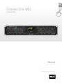 1
1
-
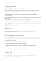 2
2
-
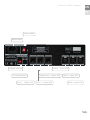 3
3
-
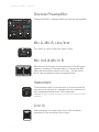 4
4
-
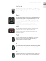 5
5
-
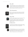 6
6
-
 7
7
-
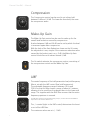 8
8
-
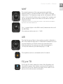 9
9
-
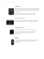 10
10
-
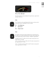 11
11
-
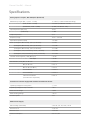 12
12
-
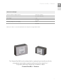 13
13
-
 14
14
-
 15
15
-
 16
16
-
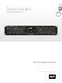 17
17
-
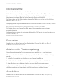 18
18
-
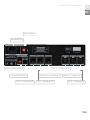 19
19
-
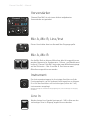 20
20
-
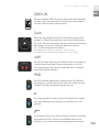 21
21
-
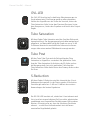 22
22
-
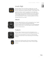 23
23
-
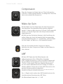 24
24
-
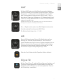 25
25
-
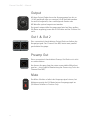 26
26
-
 27
27
-
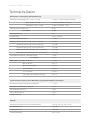 28
28
-
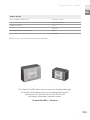 29
29
-
 30
30
-
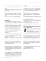 31
31
-
 32
32


Sound Performance Lab Channel One Mk3 Bedienungsanleitung
- Kategorie
- Audio-Equalizer
- Typ
- Bedienungsanleitung
